Note: Descriptions are shown in the official language in which they were submitted.
CA 02519079 2005-09-13
WO 2004/085783 PCT/US2004/008916
DRIVE SYSTEM FOR GARAGE DOOR
Field of the Invention
The invention relates generally to a drive system
for shifting a movable barrier and, more particularly, to
a drive system for shifting a garage door using a
flexible actuator.
Background of the Invention
Garage door systems, such as shown in U.S. Patent
Nos. 5,803,149 and 6,326,751, include a garage door that
is normally shifted between a substantially vertical
orientation, where the door is in a closed position, and
a substantially horizontal position, where the door is in
an open position. Jack shaft operators as disclosed in
the 1149 patent are available that employ a spring-loaded
drive shaft to assist in controlled shifting of the heavy
weight of the door as it is moved between its horizontal
open and vertical closed positions along a guide track as
CA 02519079 2005-09-13
WO 2004/085783 PCT/US2004/008916
by application of a counterbalancing force thereto. For
lifting the door open, a pull cable connected near the
bottom of the door is spooled on a drum mounted to the
rotating shaft.
Garage door systems have been developed that also
use an upper cable operatively connected adjacent the top
of the door to pull the garage door from the open
position to the closed position. The upper cable is
tensioned with an extension spring, such as disclosed in
the aforementioned patents. The 1751 patent also shows a
torsion spring that exerts a torsional or rotational
force on links that are pivotally connected in order to
tension the cable. Such a torsion spring and link
arrangement introduces undesirable complexities and pivot
points that can quickly wear and fail with repeated
cycling and especially over prolonged periods of garage
door operation.
During winding and unwinding of the cables from the
drum or drums, the cables are more likely to spool onto
the drums improperly or actually fall off of the drums,
also known as cable throw, unless properly tensioned. In
particular, the cable not bearing, the majority of the
load tends to come off of its drum unless properly
tensioned. For example, when the door is nearly to its
closed position, the majority of the door's weight is
- 2 -
CA 02519079 2005-09-13
WO 2004/085783 PCT/US2004/008916
supported by the lower cable, thus reducing the tension
in the upper cable which, unless proper tension is
applied, results in cable throw. Cable throw causes the
improper winding and/or unwinding of the cable from the
drum, resulting in the malfunction of the garage door
system in terms of properly opening and closing as is
desired.
The use of extension or coil springs to tension
upper cables of garage door systems is problematic from a
security standpoint. More specifically, extension,
springs are attached between the upper cable and the
door. Generally, there is a pivotal bracket arm attached
adjacent the upper end of the door at one end and to a
roller at its other end with the spring operatively
attached 'between the arm and cable., Accordingly, with
the door closed, the spring allows an intruder to exert
an upward lifting force on the door to push the roller in
the guide track with the spring deflecting or stretching,
thus raising the door despite lack of rotation of the
drive shaft and drum on which the upper cable is spooled.
In other words, the intruder can lift the door by way of
spring deflection, even though the length of the upper
cable between the drum and spring does not increase. The
intruder usually will be able to lift the door by
deflection of the spring by a vertical amount sufficient
3 -
CA 02519079 2005-09-13
WO 2004/085783 PCT/US2004/008916
so that they can gain access to the interior of the
garage by fitting under the door, e.g., by Lifting the
door by a height off the ground large enough for the
intruder to pass through. Further, if the yield strength
of the spring is exceeded, the overflexed spring may not
be able to exert the same tensioning force n the cable
and generally will see its usable spring life cycles
reduced. In some instances an intruder may stretch the
spring so that the spring breaks, thereby allowing the
garage door to be lifted completely up.
A further complication in designing drive systems
comes from the use of multi-panel doors that travel
curved paths as these doors move between open and closed
positions. As the panels pivot relative to adjacent
panels during travel along the curved path, the
respective distances traveled by between the top end and
the bottom end of the door are not the same for a given
elevation of the door. Since the upper and lower cables
are attached to these ends of the garage door, the length
of travel required of the upper cable also -varies
relative to the length of travel required of the lower
cable as the door is raised and lowered. The variance in
the travel distance of the cables can cause fluctuations
in the tension in the cables, which can result in the
build up of slack and thus cable throw.
- 4 -
CA 02519079 2005-09-13
WO 2004/085783 PCT/US2004/008916
Summary of the Invention
In accordance with the invention, a drive system for
a moveable barrier, e.g., garage door, is provided that
limits unauthorized shifting thereof. In particular, the
drive system includes a biasing mechanism having a
biasing member, such as a compression spring, associated
with a flexible actuator, e.g., cable or chain, operably
connected between a drive shaft and the door such as
toward the upper end thereof for keeping the cable
actuator tensioned. The biasing mechanism also includes
a stop assembly which provides a well-defined, generally
precise limit to the amount of deflection or flexing the
compression spring can undergo. In this way, the present
biasing mechanism incorporating the stop assembly only
allows the garage door to be lifted from the closed
position without operation of the drive shaft by a
predetermined small, vertical distance that is
insufficient in terms of allowing unauthorized access to
the garage. At the same time, the stop assembly does not
allow the spring to be overf lexed even when the stop
assembly is operable to stop unauthorized door shifting
thus maintaining spring performance for actuator
tensioning and maximizing the life thereof.
It is preferred that the biasing member exert a
linearly directed biasing force with the stop assembly
-. 5 -
CA 02519079 2005-09-13
WO 2004/085783 PCT/US2004/008916
being connected to the mechanism for similarly flexing
the member in the linear direction, preferably in line
with the cable actuator. In this way, operation of the
biasing mechanism and stop assembly thereof do not
require pivot members for transmission of the tensioning
force to the cable and the wear and reliability problems
these pose.
As is apparent, this linearly directed biasing force
is akin to that provided by prior extension springs
which, however, lack the stop assembly of the present
invention. In this manner, the present biasing mechanism
can be implemented in much the same manner as prior
extension springs in terms of the surrounding hardware
necessary for attaching it between the cable and the
door. For instance, the normal arm having a roller
riding in the guide track for the door and being
pivotally mounted to the upper end of the door at one end
with the other having a bracket for pivotally attaching
to the present biasing mechanism can generally still be
employed with only relatively minor modifications
thereto. Accordingly, the present drive system can more
easily be substituted for prior systems employing
extension springs with a minimum of added expense and
effort for installation and retrofitting thereof.
In the preferred and illustrated form, the biasing
6 -
CA 02519079 2005-09-13
WO 2004/085783 PCT/US2004/008916
mechanism and connected stop assembly are a commercially
available extension spring assembly that include pull
devices. The pull devices include a pair of elongate U-
shaped loops that each pass through the barrel of the
coils in opposite directions to each other- and hook
around- the opposite end coils of the spring so that when
a tension force is applied to the loops, they pull toward
each other compressing the spring coils together. Once
the coils are completely compressed, there is a hard,
physical limit to the deflection of the spring regardless
of loading so that the garage door cannot be lifted
further once this point is reached. In addition, this
prevents the spring from being overflexed or
overstretched which otherwise can adversely effect the
bias force applied by the spring to keep the cable
tensioned and can reduce spring life.
It should be noted that the construction of the
present spring assembly is interchangeably called an
extension or a compression spring as it includes physical
characteristics of both. Common characteristics include
loops that in operation are pulled away from each other
similar to expansion springs. The loops are connected to
hooks of the pull devices that are operable to pull the
opposing end coils toward each other to compress the
coils together like operation of a compression spring
7 -
CA 02519079 2005-09-13
WO 2004/085783 PCT/US2004/008916
when the loops are pulled as described. Nevertheless,
the present spring assembly is constructed to provide
additional advantages over simple extension or
compression springs, as described herein.
More specifically and in a preferred form, the
present drive system is employed with a jack shaft garage
door operator including a drive shaft that is driven to
raise the garage door from the closed position via a
lower cable that is taken up to pull the door toward the
open position while the upper cable pays out.
Conversely, when the drive shaft is driven to lower the
garage door from the open position, the upper cable is
taken up to pull the door toward the closed position
while the lower cable pays out. Once the upper cable
begins to urge the garage door toward its closed
position, the lower cable assists in supporting the
weight of the door as it is being lowered.
As mentioned, the biasing mechanism is provided
between the cable and the garage door in order to provide
tension to the upper cable. The biasing mechanism
includes a spring, as discussed above, to provide
sufficient tension to the cable to prevent the cable from
being thrown off of the drum or otherwise hindering
movement of the door. The spring of the biasing
mechanism is configured to apply tension to the flexible
- 8 -
CA 02519079 2005-09-13
WO 2004/085783 PCT/US2004/008916
actuator within a range before the spring is completely
compressed to a predetermined maximum limit i.e., about
two inches. When the predetermined maximum limit is
reached, the stop assembly does not allow further
resilient flexing of the spring and movement of the
garage door beyond the predetermined limited amount when
the drive shaft is not rotated.
Many garage doors include a plurality of pivotally
connected panels with connected rollers positioned within
the guide track. The track has a generally vertical
portion for supporting the garage door in the closed
position and a generally horizontal portion for
supporting the door in the open position. Connecting the
vertical and horizontal track portions is an arcuate
portion.
As the rigid panels are pivoted for articulating to
travel along the arcuate track portion, the upper and
lower cables will travel by different distances with
respect to each other for a given position of the garage
door between the closed and open positions. As one is
being paid out and the other is being taken up by the
rotating drum(s) to which they are secured, as previously
discussed. It has been found that the travel differences
between the cables vary and oscillate in a fairly
predictable range that can be measured. At different
- 9 -
CA 02519079 2005-09-13
WO 2004/085783 PCT/US2004/008916
positions of the door between its open and closed
positions, there is a travel differential amount, i .e . ,
the difference the upper cable has traveled relative to
the lower cable. The travel differential amount varies
depending upon the position of the garage door.
Throughout the travel of the door there is ~=_k largest
measured difference, which is termed the maximum travel
differential amount. As is apparent, since the cable
drum is mounted on the rotating drive shaft that is fixed
in position relative to the door, the lack cf a constant
one-to-one correspondence between the cable travel
distances creates slack in the cables, and most typically
the upper cable, during garage door operations.
While prior extension springs would generally allow
a sufficient amount of deflection to take-up the maximum
travel differential amount so as to keep the cables
tensioned during garage door operations, these springs
are typically oversized in that they have almost no
practical limit on the maximum deflections, thereby
allowing far greater deflection that the maximum
differential travel amount. In other words , there has
been no consideration given to the travel differential,
and certainly these prior drive systems hav not
identified the maximum travel differential as being of
importance.
- 10 -
CA 02519079 2005-09-13
WO 2004/085783 PCT/US2004/008916
Accordingly, in another form of the invention, a
drive system is provided that has a pair of flexible
actuators, i . e . , cables, connected to shift the movable
barrier. A resilient take-up device that provides one of
the actuators with a biasing force by resilient
deflection or flexing minimizes slack in the actuator due
to the travel differential. The take-up device is
provided with a limit assembly which defines a
predetermined maximum limit of deflection of. the take-up
device. In particular, the limit assembly allows the
maximum deflection limit to be preselected to generally
correspond to the maximum travel differential. In this
way, the present take-up device can be carefully tailored
to provide the deflection or flexing and bias force to
the flexible actuator that is needed to avoid slack due
to travel differential, while avoiding the over sizing
thereof as occurred with prior extension springs that
were not selected based on an identification of the
maximum travel differential amount similar to the take-up
device incorporating the limit assembly herein. At the
same time, the limit assembly avoids overf lexing of the
take-up device such as could occur if an intruder is
attempting to push the door up, which could deflect and
stretch the prior extension springs of the upper cables
until they can gain access by fitting under the door to
- 11 -
CA 02519079 2005-09-13
WO 2004/085783 PCT/US2004/008916
the garage.
As previously discussed, the resilient take-up
device is preferably in the form of a compression coil
spring and the limiting stop assembly preferably includes
a pair of opposing drawbars having the compression spring
positioned therebetween. The drawbars and spring are
configured and arranged to apply tension to the cable
when the drawbars are drawn toward each other due to the
biasing force\ of the spring. When the spring coils are
fully compressed between the drawbars, the maximum limit
of applied tension to the flexible actuator is reached.
The engagement of the drawbars against the fully
compressed coils of the spring prevents further extension
of the flexible actuator, thereby allowing the upper
cable to ' become taunt. If this point has been reached
without rotation of the drive shaft, i.e., by an intruder
lifting the door, further unauthorized shifting of the
garage door is prevented.
Over time, the cable may stretch and deform so that
it is longer than its initial length. If the cable
increases in length, then the biasing mechanism is
required to take up the slack in the cable so that
tension in the cable stays relatively constant. The
compression spring needs to deflect or expand axially
taking up the preload initially set therein as described
12 -
CA 02519079 2005-09-13
WO 2004/085783 PCT/US2004/008916
hereinbelow thus requiring an increase the length between
opposite end coils to pull the two opposing drawbars
closer together, and particularly the loop connection
points thereof. However, as mentioned above, the
distance between the two opposing drawbars and the
preloaded, partially compressed axial length of the
spring are carefully selected to permit deflection of the
spring generally corresponding only to the maximum travel
differential amount. The change in the distances in the
drawbar spring assembly, such as by taking up slack in an
elongated cable, reduces the ability of the spring
assembly to compensate for the predetermined maximum
travel differential amount. In other words, if the coil
spring becomes axially longer than it is in its
preloaded, partially compressed state, the drawbars will
no longer fully compress the cables when the maximum
travel differential amount is reached.
In order to maintain a generally constant maximum
differential travel amount, even when the upper cable
lengthens over time, herein a tensioner is provided
between the arm pivotally attached to the door at one end
and to the spring assembly at its other end. The
distance between the connection point of the tensioner
relative to the arm is made to be adjustable. The
tensioner includes an adjustment device so that the
13 -
CA 02519079 2005-09-13
WO 2004/085783 PCT/US2004/008916
connection point can be controllably shifted relative to
the arm in order to change the distance between the
connection point and the drive shaft prior to garage
operations. In this manner, the preload tensioner allows
a user to more precisely set the tension in the upper
cable during system set-up procedures, such as with the
door in its closed position. Shifting the connection
point further away from the shaft via the preload
tensioner allows for the take up of slack in an elongated
upper cable to maintain the spring at its preload,
partially compressed axial length which accommodates the
maximum travel differential amount.
The tensioner may include a supplemental adjustment
mechanism that causes the connection point to
automatically shift away from the shaft, such as in
predetermined increments, to take up slack in the upper
cable. In this manner, the tensioner is adapted to allow
the drawbar and compression spring assembly to maintain a
generally constant range of tension on the cable, even as
the cable is stretched and lengthens over time, so that
the drawbar and spring assembly stays tailored to address
only the necessary amount of the travel differential
between the upper and lower cable actuators, namely the
maximum travel differential amount as described
hereinabove.
- 14 -
CA 02519079 2010-06-09
According to one aspect of the present invention
there is provided a movable barrier system comprising a
moveable barrier shiftable between open and closed
positions; a drive shaft driven for rotation to shift the
barrier between one of the open and closed positions to
the other of the open and closed positions; an actuator
assembly including a flexible actuator connected between
the drive shaft and the barrier for shifting the barrier
from the one position to the other upon rotation of the
drive shaft; a biasing mechanism including a resilient
biasing member between the flexible actuator and the
barrier that exerts a generally linear biasing force in a
predetermined linear direction for keeping the flexible
actuator tensioned as the barrier is shifted; and a stop
assembly of the biasing mechanism that keeps resilient
flexing of the biasing member and shifting of the barrier
absent drive shaft rotation from the other position
toward the one position to a predetermined limited
amount, the stop assembly including connections to the
biasing member to resiliently flex the member along the
linear direction upon shifting of the barrier absent
drive shaft rotation, and the resilient biasing member
comprises a compression spring, and the stop assembly
includes a pair of pull devices with one of the pull
devices operatively connected to the flexible actuator
and the other of the pull devices operatively connected
to the barrier, the pull devices and compression spring
being configured to compress the spring therebetween when
the barrier is shifted from the closed position toward
the open position absent drive shaft rotation until the
barrier reaches the predetermined limited amount of
shifting.
14a
CA 02519079 2010-06-09
According to a further aspect of the present
invention there is provided a movable barrier system
comprising a moveable barrier shiftable between open and
closed positions; a drive shaft driven for rotation to
shift the barrier between one of the open and closed
positions to the other of the open and closed positions;
an actuator assembly including a flexible actuator
connected between the drive shaft and the barrier for
shifting the barrier from the one position to the other
upon rotation of the drive shaft, the flexible actuator
extending between an end of the barrier and the drive
shaft and another flexible actuator extending between an
opposite end of the barrier and the drive shaft, the
flexible actuators undergoing different relative travel
amounts to define a travel differential therebetween that
varies up to a maximum differential travel amount as the
barrier is shifted between the open and closed positions;
a biasing mechanism including a resilient biasing member
between the flexible actuator and the barrier that exerts
a generally linear biasing force in a predetermined
linear direction for keeping the flexible actuator
tensioned as the barrier is shifted; and a stop assembly
of the biasing mechanism that keeps resilient flexing of
the biasing member and shifting of the barrier absent
drive shaft rotation from the other position toward the
one position to a predetermined limited amount, the
biasing mechanism having the stop assembly arranged to
allow the biasing mechanism to take-up the maximum
differential travel amount so that the maximum
differential travel amount substantially corresponds to
the predetermined limited amount of barrier shifting
allowed by the biasing mechanism and stop assembly.
14b
CA 02519079 2010-06-09
According to another aspect of the present invention
there is provided a system for shifting a moveable
barrier between predetermined positions, the drive system
comprising a first flexible actuator adopted to be
operably connected to the barrier to shift the barrier
from a first one of the predetermined positions to a
second one of the predetermined positions; a second
flexible actuator adopted to be operably connected to the
barrier to shift the barrier from the second
predetermined position to the first predetermined
position, the first and second flexible actuators
undergoing different travel amounts relative to each
other to define a travel differential therebetween that
varies up to a maximum differential as the barrier is
shifted between the predetermined positions thereof; a
resilient take-up device associated with the first
flexible actuator that provides a bias force to the first
actuator by a resilient deflection thereof to minimize
slack in the first actuator due to the actuator travel
differential during barrier shifting; and a limit
assembly of the take-up device which defines a
predetermined maximum level of deflection of the take-up
device to avoid overflexing thereof and allowing the
predetermine maximum deflection level of the take-up
device to be preselected to generally correspond to the
maximum actuator travel differential for keeping the
predetermined maximum deflection level to a minimum.
According to a still further aspect of the present
invention there is provided a system for a moveable
barrier that is shifted between open and closed
positions, the drive system comprising a drive shaft
driven for rotation and adopted for connection to a
barrier to shift the barrier between one of the open and
14c
CA 02519079 2010-06-09
closed positions to the other of the open and closed
positions; a drum assembly including a drum mounted for
rotation with the drive shaft and allowing a
predetermined amount of relative rotation therebetween;
an actuator assembly including a flexible actuator
connected between the drum and the barrier for shifting
the barrier from the one position to the other upon
rotation of the drive shift, the flexible actuator being
taken upon the drum during shifting from the one position
to the other position and being taken from the drum
during shifting from the other position to the one
position; a biasing mechanism including a resilient
biasing member operatively connected between the drum and
the drive shift that exerts a biasing force for keeping
the flexible actuator tensioned as the barrier is
shifted; and a stop mechanism of the drum assembly that
limits shifting of the barrier absent drive shaft
rotation from the other position toward the one position
to a predetermined limited amount corresponding the
predetermined amount of relative rotation between the
drum and the drive shaft and wherein the flexible
actuator extends between an end of the barrier and the
drum and another flexible actuator extends between an
opposite end of the barrier and the drive shaft, and the
flexible actuators undergo different relative travel
amounts to define a travel differential therebetween that
varies up to a maximum differential travel amount as the
barrier is shifted between the open and closed positions,
and the drum assembly has the stop mechanism arranged to
allow the biasing mechanism to take-up the maximum
differential travel amount so that the maximum
differential travel amount substantially corresponds to
the predetermined limited amount of barrier shifting
14d
CA 02519079 2010-06-09
allowed by the predetermined amount of relative rotation
between the drum and the drive shaft.
14e
CA 02519079 2005-09-13
WO 2004/085783 PCT/US2004/008916
Embodiments are also described herein in which a
torsion drum is used as a tensioner. The tension drum is
connected by a torsion spring to the rotation of a shaft
and can rotate with respect to the shaft subject to the
restoration force of the torsion spring. Stops to limit
the rotation of the torsion drum with respect to the
shaft are also provided.
Brief Description of the Drawings
FIGURE 1 is a perspective view of a garage door in a
closed position thereof and a drive system therefore
including a drive shaft and upper and lower flexible
cable actuators operatively attached to the door in
accordance with an embodiment of the invention;
FIGURE 2 is an enlarged perspective view of the
drive system showing a spring assembly attached between
the upper cable and an arm pivotally attached adjacent
the upper end of the door with spring assembly coils that
are compressed to apply a tension force to the cable as
the door is being shifted;
FIGURE 3 is a view similar to FIGURE 2 showing the
door lowered closer to its closed position with the coils
of the spring assembly expanded for decreasing the
applied tension force to the cable;
- .15 -
CA 02519079 2005-09-13
WO 2004/085783 PCT/US2004/008916
FIGURE 4 is perspective view of the spring assembly
showing a compression spring and a pair of drawbars
extending therethrough with each drawbar including a.
connection loop and a hook end;
FIGURE 5 is a perspective view of a preload
tensioner for the drawbar spring assembly showing a
turnbuckle including hook screws threaded thereto
connected to a bracket attached to the arm pivotally
connected to the upper end of the door at one end and to
one of the drawbar loops at the other end for keeping the
preload in the spring substantially constant during
garage door operation;
FIGURE 6 is a perspective view of another preload
tensioner for the drawbar spring assembly showing a hook
screw threaded into a block attached to the arm pivotally
connected to the upper end of the door and having one of
the drawbar loops connected at the hook end for keeping
the preload in the spring substantially constant during
garage door operation;
FIGURE 7 is a perspective view of a self-adjusting
preload tensioner for the drawbar spring assembly showing
a hook screw inserted through a block attached to the arm
pivotally connected to the upper end of the door and
threaded into a split nut and having a spring biasing the
screw from the block and having one of the drawbar loops
16 -
CA 02519079 2005-09-13
WO 2004/085783 PCT/US2004/008916
connected at the hook end on the other side of the block
for keeping the preload in the spring substantially
constant during garage door operation;
FIGURE 8 is a perspective view of the self-adjusting
preload tensioner of FIGURE 7 with the spring removed
showing the split nut and a cap on the threaded end of
the hook screw against which the spring of FIGURE 7
biases the screw from the block;
FIGURE 9 is a chart comparing the differences
between travel of the upper flexible cable actuator and
the lower flexible cable actuator of the system of FIGURE
1 to the elevation of the garage door as it travels from
its closed position to its open position;
FIGURE 10 is a perspective view of a barrier
movement system including a torsion drum;
FIGURE 11 is an exploded perspective view of a
torsion drum;
FIGURE 12 is a perspective view of an assembled
torsion drum mounted on a sectioned drive shaft;
FIGURE 13 is a plain view of a back side of the
torsion drum of FIGs. 10-12;,
FIGURE 14 is a perspective view of a barrier
movement system having a chain as a flexible actuator-;
FIGURE 15 is a view of a sprocket, chain and chain
guide of FIG. 14; and
- 17 -
CA 02519079 2005-09-13
WO 2004/085783 PCT/US2004/008916
FIGURE 16 is a perspective view of a barrier
movement system having a belt as a flexible actuator.
Detailed Description of Preferred Eaodinents
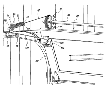
In FIGURES 1-3, a garage door 20 and its drive
system 10 are shown for shifting the door 20 between a
closed position (FIGURE 1) and an open position in
accordance with the.present invention. More
particularly, the drive system 10 includes a lower cable
44 that exerts a lifting force on the vertical door 20 as
it is shifted to the open position, which as shown will
be with the door 20 in a generally horizontal orientation
due to the configuration of its guide track 60. Most
residential garage door systems will have a vertical
portion or run 66 that guides the door to its closed
position and a horizontal portion or run 62 adjacent and
below the ceiling of the garage 5 so that the door 20 is
lifted open to a horizontal position. A curved or
arcuate track portion 64 interconnects the vertical and
horizontal track runs 66 and 62, as is known. For
shifting the door 20 closed, the present drive system 10
includes an upper cable 42 that is operable to exert a
closing force on the door 20.
With the drive shaft 30 being a component of th4a
- 18 -
CA 02519079 2005-09-13
WO 2004/085783 PCT/US2004/008916
typical jack shaft operator 32 and disposed over the
garage door opening 7 as shown in FIGURE 1, and having
drums 36 on which the cables 42 and 44 are spooled, the
lower cable 44 is operatively connected toward the lower
end of the door 20, and the upper cable 42 is operatively
connected toward the upper end of the door 20. In this
regard, an extension arm 122 is pivotally attached to the
door 20 via a bracket 124 and pivot pin 126 at one end of
the arm 122. As best seen in FIGURE 2, a biasing
mechanism or resilient take-up device 50 is shown
pivotally attached between the other end of the arm 122
via a bracket 128 secured thereto. The biasing mechanism
50 keeps tension in the cable 42 so that it does not
develop slack during garage door operations .
The biasing mechanism 50 is also provided with a
stop or limit assembly 70 that provides a hard stop to
the maximum deflection the biasing member in the form of
a coil spring 52 can undergo. In the present embodiment
the stop or limit assembly includes drawbars 72 and 172.
In this manner, unlike prior extension springs, the
present biasing mechanism 50 provides a precise, known
limit to how much shifting the door 20 can undergo
without operation of the rotating drive shaft 30.
Accordingly, with the door 20 closed an intruder
attempting to gain access to the interior space of the
19 -
CA 02519079 2005-09-13
WO 2004/085783 PCT/US2004/008916
garage S. will only be able to lift the closed garage door
20 off from the ground by a predetermined limited amount
which is defined by the arrangement of the coil spring 52
and the stop assembly 70. On the other hand, the present
biasing mechanism 50 employs the coil spring 52
advantageously as it applies a linear bias force for
tensioning the cable 42 with the force in line or coaxial
with the cable 42 so as to keep the number of pivoting
parts in the present biasing mechanism 50 to. a minimum.
In addition, by utilizing a coil spring 52 similar to
prior extension coils springs but having a stop assembly
70 incorporated therewith, the present biasing mechanism
50 can be more readily installed in current garage door
drive systems that employ an upper cable with an
extension spring for keeping tension thereon without
requiring significant modifications thereto. In the
preferred form, the present biasing mechanism 50 can be a
commercially available drawbar spring assembly such as
provided by McMaster-Carr of Chicago, Illinois. These
spring assemblies 50 have a size or form similar to prior
extension springs so they can be easily substituted
therefor. Furthermore, this allows the drive system 10
incorporating the biasing mechanism 50 as described
herein to be implemented with a minimum of expense as
custom made parts therefor are avoided.
20 -
CA 02519079 2005-09-13
WO 2004/085783 PCT/US2004/008916
Referring to FIGURE 4, the drawbar assembly 70
includes a pair of drawbars 72 and 172 that extend
through the barrel of the spring coil 52 in opposite
directions. The drawbars 72 and 172 each include a loop
76 or 176 at one end and hooks 74 or 174 at the other
end. Accordingly, there is a loop 76 of one drawbar 72
that projects beyond one end of the coil spring 52 while
the hooks 174 of the other drawbar 172 are engaged about
the coils thereat. The loop 76 is connected to the end
of the upper cable 42 while the other loop 176 is
connected to the bracket 128 of the arm 122 , as best seen
in FIGURES 2 and 3. Thus, the coil spring 52 is loaded
by axial compression such as during system set-up for
preloading thereof as will be described hereafter, and
during garage door operations either by the arm 122
pushing on the loop 176 causing the hooks 174 to pull on
the end coil for compressing the coils during door
opening operations, or by take-up of the cable 42 on the
drum pulling on drawbar loop 76 causing hook end 74 to
pull on the end coil for compressing the coils 52 during
door closing operations. Accordingly, unlike prior
extension springs, there is an axial shortening of the
coil spring 52 that is effective to load the biasing
mechanism 50 for keeping tension on the upper cable 42.
In each instance when the door 2 0 shi f: is as by drive
21 -
CA 02519079 2005-09-13
WO 2004/085783 PCT/US2004/008916
shaft rotation, the above-described arrangement of the
drawbars 72 and 172 allows the assembly 50 to exert a
linear compressive force on the coil spring 52 aligned
with the force applied by the spring assembly 50 to the
upper cable 42. As is apparent, the drawbars 72 and. 172
can only pull the coils together until they all are
engaged with adjacent coils. At this point , the col l
spring 52 can not be deflected further, thereby providing
a well-defined limit to its maximum deflection which
cannot be exceeded. In this manner, the present spring
assembly 50 cannot be overflexed as possible with prior
extension springs. Importantly, the hard limit provided
to the spring deflection is effective in stopping
unauthorized entry into the garage door space 5 as no
longer will an intruder be able to continually stretch
and deflect the spring 52 of the upper cable 42 until
they can fit under the door 20. Again, this overflexing
is avoided with the present drawbar spring assembly 5 0
along with the potential for plastic deformation thereof,
and even complete failure of the coil spring 52. More
specifically, when an intruder attempts to open the fully
closed garage door 20 without the drive shaft 30 being
driven for rotation by the operator motor 34, the garage
door 20 will initially move along the track 60 toward its
open position with the lower end of the door 20 raised
22 -
CA 02519079 2005-09-13
WO 2004/085783 PCT/US2004/008916
off from the ground. While the garage door 20 is being
lifted upwardly, the distance between the drawbar 176 and
arm 122 connection and the drum 36 increases from its
nominal distance, with the upper cable 42 tensioned and
coils of the compression spring 52 shifting axially
toward each other. When the coils have shifted linearly
along their axis by the maximum deflection amount due to
the lifting force, they are fully axially compressed
between the hooks 74 and 174 of the opposing drawbars 72
and 172 so that with the upper cable 42 fully taunt the
door 20 cannot undergo any further upward movement as
might allow an intruder access to the garage interior
space 5.
As the drawbar spring assembly 50 is commercially
available in different sizes, it can be selected so that
the amount of shifting or lifting of the door 20 absent
drive shaft rotation and motor operation will be known in
advance, with allowance taken in to account for
preloading of the spring assembly 52, as will be
described herein. The limited amount of shifting that is
allowed can be selected to be, for example, approximately
two inches with the coil spring 52 preloaded as by
axially compressing the coils by approximately two inches
with the door 20 lifted off of the ground by this short
vertical distance, e.g. two inches, at which point
23 -
CA 02519079 2005-09-13
WO 2004/085783 PCT/US2004/008916
further raising of the door 20 cannot occur substantially
irrespective of the manual lifting force applied by an
intruder, and they will be unable to fit under to door 20
to effectively keep them out of the garage interior space
5.
Many garage doors 20 are of a multi-panel
construction including several panels 26 that are hinged
together to allow them to pivot relative to each other.
As seen best in FIGURES 1-3, the panels 26 have a hinge
28 adjacent each lateral side thereof and in the mid-
section thereof. The hinges 28 each include an upper
hinge portion 132 attached to the lower end of the upper
adjacent panel 26 and a lower hinge portion 134 attached
to the upper end of the lower adjacent panel 26.
Connecting the two hinge portions 132 and 134 is a pivot
pin 136 that allow the hinge portions 132 and 134, and
thus the adjacent door panels 26, to pivot relative to
each other.
Rollers 24 are positioned to extend past the lateral
edges of the door 20 for traveling in the track portions
62, 64, and 66. The rollers 24 are mounted in several
locations. Some of the rollers 24 are mounted to the
hinges 28 adjacent the lateral edges of the panels 26 via
pins 27 with rollers 24 on the ends thereof rotatable
mounted thereto. As best seen in FIGURE 2 , the roller
- 24 -
CA 02519079 2005-09-13
WO 2004/085783 PCT/US2004/008916
pins 27 can be mounted to the lower hinge portions 134.
The roller pin 27 and the pivot pin 136 may also be
combined. That is, the same pin that pivotally connects
the upper and lower hinge portions 132 and 134 may also
extend past the lateral edge of the door panel 26 and
have a roller 24 mounted thereto for travel in the track
60. Other rollers 24 may have their roller pins 27
mounted to the garage door 20 via brackets 29 and 124
independent of the hinges 28. For example, rollers 24
may be mounted to pins 27 attached to brackets 29 and 124
fixed adjacent to lateral edges of the door 20 at the top
end of the uppermost panel 26 and the bottom end of the
lower most panel 26 for guiding the top and bottom of the
door 20. Rollers 24 are also mounted relative to both
ends of the arm 122 to guide the arm 122 along the track
60. These rollers 24 have pins 27 that extend through
holes in the end of the arm 122 pivotally attached to the
door 20 with a hinge bracket 124 and the end opposite the
door 2 0.
The positions of the rollers 24 relative to the
panels 26 and the arm 122 are carefully selected to allow
the door panels 26 and arm 122 to travel through the
arcuate portion 64 of the track 60. For instance, the
rollers 24 are positioned near the top and bottom ends of
the panels 26 and arm 122, as opposed to in the
25 -
CA 02519079 2005-09-13
WO 2004/085783 PCT/US2004/008916
midsections thereof, to allow the panels 26 and arm 122
to move through the arcuate track portion 64 as the
panels 26 and arm 122 transition between horizontal and
vertical orientations. As illustrated in FIGURE 1, for a
S garage door 20 having four panel sections 26 five rollers
24 are positioned along each lateral side thereof for
travel in the track 60, along with one roller 24 at the
end of the arm 122 opposite the connection of the arm. 122
to the uppermost panel 26 of the door 20. Rollers 24 are
mounted to brackets 29 attached toward the bottom end of
the bottom most panel 26. A pair of rollers 24 are also
connected to a combined. pivot pin and roller pin 126
joining the upper and lower hinge portions 132 and 134 of
the hinge 28 connecting the lowermost panel 26 to the
panel 26 'adjacent thereto. The hinges 28 joining the two
intermediate panels 26 and the uppermost panel 26 and its
adjacent panel 26 each have a roller 24 connected to a
roller pin 27 connected to the lower hinge portion 134.
At each side of the top end of the uppermost panel 26 a
bracket 124 is provided having a roller pin 27 with a
roller 24 on the end thereof . For the side of the panel
26 having the arm 122 connected thereto, the combined
roller pin 126 also pivotally connects the arm 122 to the
bracket 124.
As the door 20 is shifting through its curved path
- 26 -
CA 02519079 2005-09-13
WO 2004/085783 PCT/US2004/008916
adjacent panels 26 pivot relative to each other which is
believed to be at least one reason for the travel
differential between the upper and lower cables 42 and
44, as previously described. The present da:-ive system 10
via the resilient take-up device 50 and limit assembly 70
is very well adapted to keep proper tension on the cables
42 and 44 despite the travel differential therebetween
during garage door operations. In this regard, the
resilient take-up device 50 including the limit assembly
70 is sized with precision to deflect the coil spring 52
by no more than is needed to accommodate the maximum
amount of travel differential between the ;cables 42 and
44. In this way, the size of the take-up device 50 in
terms of how much resilient deflection it needs to be
15' able to undergo is kept to a minimum.
Where the resilient take-up device 50 and limit
assembly 70 are as shown in their preferred form, i.e.,
the drawbar spring assembly 50 as shown in FIGURE 4,
another advantage is that by minimizing the maximum
resilient deflection that is selected, the predetermined
limited amount of unauthorized garage door 20 shifting
allowed by the device is also kept to a minimum. In
other words, the maximum resilient deflection is the
linear distance that the coils can be shifted or
compressed along their axis before they are engaged
27 -
CA 02519079 2005-09-13
WO 2004/085783 PCT/US2004/008916
together or fully compressed by the pulling force on the
drawbars 72 and 172. As such, this maximum resilient
deflection level also defines the limited amount of door
20 shifting that can occur absent drive shaft rotation.
Accordingly, identifying the maximum travel differential
between the cables 42 and 44 as done herein allows the
drawbar spring assembly 50 to be selected in a way that
also affords optimized advantages as the limited amount
of allowed door 20 shifting can be kept to a minimum.
As discussed above, the biasing mechanism 50 is
preferably preloaded such that the spring 52 is in a
partially compressed state when the garage door 20 is in
its closed position to tension the upper cable 42. The
length of the upper cable 42 when the garage door 20 is
in the closed position and/or the size of the spring and
drawbar assembly 50 are selected so that the spring 52 is
partially compressed to the preselected amount that
allows for the spring 52 to be compressed an amount
corresponding to the maximum differential travel amount.
A supplemental tensioner 80, 89, or 90 is provided to
allow for adjustment of the axial distance the spring 52
can compress from its partially compressed state, i . e . ,
when the garage door 20 is in its closed position, to its
fully compressed state, to achieve only the amount of
garage door 20 travel necessary to compensate for the
- 28 -
CA 02519079 2005-09-13
WO 2004/085783 PCT/US2004/008916
maximum travel differential amount before further travel
is prevented by the stop assembly 70.
Adjustments may be needed when installing a drive
system 10 in accordance with the invention, and when
retrofitting an existing system with the biasing
mechanism 50. In particular, the supplemental tensions
80, 89, and 90 allow for the fine-tuning of the biasing
mechanism 50. Adjustments may also be needed
periodically over time during use of the garage door
drive system 10 due to stretching, and thus an increase
in length, of the cables 42 and 44. For example, if the
upper cable 42 increases in length, the spring 52 of the
biasing mechanism 50 must increase in axial length from
its preselected preload length to take up the slack
therein due to the increased length thereof . As
discussed above, an increased preload spring 52 axial
length will allow the garage door 20 to travel from its
closed position a greater distance before further travel
is prevented by the stop assembly 70 fully compressing
the spring 52.
The supplemental tension 80, as shown in FIGURE 5,
includes a turnbuckle 82 having hooks screws 84 and 184
with threaded ends 88 and 188 threaded thereinto. The
hooked end 86 of the hook screw 84 is connected to the
loop end 176 of the drawbar 172 of the spring and drawbar
29 -
CA 02519079 2005-09-13
WO 2004/085783 PCT/US2004/008916
assembly 50. The other hook screw 184 has its hooked end
186 connected to the bracket 128 mounted to the end of
the arm 122 opposite the end of the arm 122 attached to
the door 20 with the bracket 124. The threads of the
threaded ends 88 and 188 of the hooks screws 84 and 184
allow for the distance between the opposing hooked ends
86 and 186 thereof to be increased or decreased, which
causes the distance between the bracket 129 and the
spring and drawbar assembly 50 to increase or decrease.
When the distance is decreased, the hooked end 174 of the
drawbar 172 can be set to apply a greater preload to the
spring, compressing the spring 52 to the preselected
amount necessary allow the spring 52 to be fully
compressed once the maximum predetermined travel
differential has been reached. Conversely, increasing
the distance using the tensioner 80 allows the spring 52
to increase in axial length, increasing the amount of
travel of the door 20 before the limit assembly 70 fully
compresses the spring 52 to prevent further travel of. the
door 20.
FIGURE 6 shows a supplemental tensioner 89,
different from the tensioner 80 discussed above, that
allows for the change in distance between the end of the
arm 122 and the spring and drawbar assembly 50. The
supplemental tensioner 89 includes a hook ecrew 104
- 30 -
CA 02519079 2005-09-13
WO 2004/085783 PCT/US2004/008916
having a threaded end 102 passing through a bore in a
mounting block 130 fixed to the bracket 128 on the end of
the arm 122. The threaded end 102 threads into a nut 106
that prevents the hook screw 104 from passing back
through the bore of the block 130. The hook end 108 of
the screw 104 is connected to the loop end 176 of the
drawbar 172 of the spring and drawbar assembly 50.
Adjustment of the nut 106 either increases or decreases
the distance between the end of the arm 122 and the
connection of the hook end 108 to the spring and drawbar
assembly 50. When the distance is increased, the preload
on the spring 52 is decreased which increases the axial
travel of the spring 52 prior to full compression of the
coils thereof, allowing for greater travel of the door 20
15' from its closed position before the spring 52 is fully
compressed and the stop assembly 70 and upper cable 42
prevent further raising of the door 20. To reduce the
travel of the door 20 from its closed position before
further travel is prevented by the stop assembly 70 and
taunt upper cable 42, the distance between the end of the
arm 122 and the spring and drawbar assembly 50 is
decreased, causing the hooked ends 174 of the drawbar 172
to compress the spring 52 to have a smaller initial aerial
length, i . e . , the axial length of the spring 52 when the
door 20 is fully closed.
- 31 -
CA 02519079 2005-09-13
WO 2004/085783 PCT/US2004/008916
Another supplemental tensioner 90 is shown in
FIGURES 7 and 8 for adjusting the preload in the spring
52 of the spring and drawbar assembly 50. The loop end
176 of the spring and drawbar assembly 50 is connected
relative to the arm 122 via a hook screw 93 . The hook
screw 93 has a hook end 92 for connecting to the loop end
176 of the drawbar 172 and a threaded end 95 that passes
through a bore in a block 94 mounted to the bracket 12 8
attached to the arm 122. A split-nut 98 generally
prevents, as will be described in more detail below, the
screw 93 from passing back out the bore of the block 94
when the screw 93 is pulled upon by the spring and
drawbar assembly 50. The rotation of the split-nut 9 8 in
the clockwise direction draws the hook end 92 of the
screw 93 toward the end of the arm 122, thereby
decreasing the distance between the end of the arm 12 2
and the connection between the hook end 92 of the screw
93 and the spring and drawbar assembly 50 to increase the
precompression of the spring 52 which decreases the
distance the opposing drawbars 72 and 172 travel to f'La.lly
compress the spring 52 therebetween, such as to prevent
further travel of the door 20 from the closed position
absent rotation of the drive shaft 30. To increase the
axial length of the preloaded spring 52, causing the
drawbars 72 and 172 to travel a greater distance before
- 32 -
CA 02519079 2005-09-13
WO 2004/085783 PCT/US2004/008916
the spring 52 becomes fully compressed therebetween, the
split-nut 98 is turned counter-clockwise, thereby
increasing the distance between the end of the arm 122
and the connection between the hook end 92 of the screw
93 and the spring and drawbar assembly 50.
In addition to being moved by rotation along the
threaded portion 95 of the hook screw 93, the split-nut
98 also moves along the threaded portion 95 when the
threaded portion 95 is pulled either away from or toward
the mounting block 94 when a predetermined force is
exceeded. The split-nut 98 functions similar to a
ratchet, allowing the screw 93 to move relative to the
block 94 when the predetermined force is exceeded before
reengaging the threaded portion 95 thereof and preventing
further movement until the predetermined force is again
exceeded. A cap 99 is attached to the end of the
threaded portion 95 of the screw 93 and a spring 96 is
disposed between the block 94 and the cap 9 9 to bias the
cap 99 and thus the screw 93 away from the block 94.
The biasing force of the spring 96 is selected tc
balance the biasing force of the spring and drawbar
assembly 50 attached at the hooked end 92 of the screw 93
on the opposite side of the block 94 from the spring 96
to maintain the distance between the block 94, fixed
relative to the end of the arm 122, and the connection
33 -
CA 02519079 2005-09-13
WO 2004/085783 PCT/US2004/008916
between the hook end 92 of the screw 93 and the loop end
176 of the drawbar 172 of the spring and drawbar assembly
50 to correspond to the preloaded, precompressed axial
length of the spring 52 selected to allow the spring 52
to fully compress once the maximum differential travel
amount has been reached. If the spring 52 becomes
axially longer than its preselected length, the biasing
force of the spring 96 will be greater than the biasing
force of the spring 52, and thus the spring 96 will bias
the cap 99 and thus the threaded end 95 of the screw 93
from the block 94 to decrease the distance between the
block 94 and the hook end 92 of the screw '93 before the
spring forces are balanced and the split-nut 98 prevents
further movement, thereby causing the hooks 174 of the
drawbar 172 to preload and compress the spring 52 until
its preselected axial length is returned. Oppositely, if
,the biasing force of spring 52 becomes larger than that
of spring 95, such as when the spring 52 is precompressed
beyond its desired preload axial length, the split-nut 98
allows the threaded portion 95 of the screw 93 to move
toward the block 94 until the spring forces are balanced
96 and 52 to increase the distance between the block 94
and the hooked end 92 of the screw 93 and thus the end of
the arm 122 and the connection to the spring and drawbar
assembly 50, thereby allowing the spring 52 to expand
34 -
CA 02519079 2005-09-13
WO 2004/085783 PCT/US2004/008916
back to its preselected axial length.
Turning to more of the details, the upper and lower
cables 42 and 44 may wrap around the same drum 36, as
illustrated in FIGURE 2, or may each have separate drums
36. The drums 36 include lips 38 projecting upward on
both sides thereof for assisting in preventing cable
throw as the cables 42 and 44 are taken up thereby or
payed out therefrom. As illustrated in FIGURE 1, the
upper cable 42 may be attached only on one side of the
door 20. During door 20 travel, the upper cable 42 i s
used primarily for urging the door 20 from the open
position to the closed position, and particularly the
initial movement of the door 20 from its fully open
position. Thus, the upper cable 42, unlike the weight
bearing lower cable 44, is only necessary to be on one
side of the door 20.
To assist in raising the door 20 from its closed
position, the jack shaft operator 32 includes a large
torsion spring 38, as illustrated in FIGURE 1, that i s
configured to bias the door 20 from the closed position,
thus reducing the amount of pulling the lower cables 44
need to do as they are taken up on the drums 36 to pull
the door 20 open. When lowering the door 2 0, the spring
38 assists in counteracting the heavy weight of the door
20 in order to ensure a smooth, controlled descent
-
CA 02519079 2005-09-13
WO 2004/085783 PCT/US2004/008916
thereof. A motor 34 is operatively connected to the jack
shaft operator 32 to prevent the shaft 30 from rotating
unless caused by the motor 34. When the motor 34 causes
the shaft 30 to rotate in a first direction and the door
20 is in its closed position, the torsion spring 38 and
the taking up of the lower cables 44 on the drums 36
causes the lifting of the door. Conversely, to move the
door 20 from its fully open position, the motor 34 causes
rotation of the shaft 30 in a direction opposite the
first direction, taking up the upper cable 42 on the drum
3 6 to pull the arm 12 2 and thus the door 2 O from the open
position until the weight of the door 20 against the
biasing force of the torsion spring 38 allows the
controlled descent of the door 20.
15" The differential travel amount and the maximum
differential travel amount between upper and lower cables
42 and 44 during travel of the garage door 20 between
open and closed positions, discussed above, depends, at
least in part, on the dimensions and geometry of the
track 60 and the garage door 20. In particular, the
length of the arm 122, the height of the panel sections
26, and the radius of the arcuate portion 64 of the track
60 contribute to the differential travel amounts and the
maximum differential travel amount. For example,
analysis has shown that an arcuate portion 64 having a
36 -
CA 02519079 2005-09-13
WO 2004/085783 PCT/US2004/008916
fifteen inch radius and an eighteen inch arm 122 will
have a larger maximum differential travel amount as
compared to a twenty inch arm 122. Similarly, a
different maximum differential travel differential amount
will result for an arcuate portion 64 having a twelve
inch radius when used with an eighteen inch arm 122 as
compared to an arcuate portion 64 with a fifteen inch
radius used with an eighteen inch arm 122. These
particular configurations are discussed in greater detail
the examples and analysis below.
EXAMPLE 1
The follow example illustrates the difference in the
travel between the lower and upper cables 44 and 42 as
the garage door 20 is moved from a closed position to an
open position. The garage door 20 comprises four panel
sections 26 hinged together with hinges 28 , with each
panel 26 being approximately twenty-one inches in height,
for a total door height of approximately eighty-four
inches. An arm 122 about twenty inches in length is
pivotably connected with a bracket 124 to an upper panel
26 of the door 20 approximately six inches below its
upper edge. Rollers 24 are attached to either hinges 28
or brackets 29 and 128 and extend from the lateral edges
of the panels 26 and the arm 122 at positions similar to
those illustrated in FIGURE 1 for travel within tracks 60
37 -
CA 02519079 2005-09-13
WO 2004/085783 PCT/US2004/008916
having an arcuate portion 64 with a fifteen inch radius.
As the garage door 20 was move from its closed
position to its open position, the length and relativ-
travel of both the lower and upper cables 44 and 42 vas
measured for every twelve inches that the garage door 20
was raised from its closed position, as set forth in the
table below.
15" Door Track Radius with 20" Arm
Door Lower Lower Upper Upper Travel
Height Cable Cable Cable Cable Difference
Length Travel Length Travel (Upper - Lower)
0 96.127 0.000 12.311 0.000 0.000
12 84.122 12.005 25.072 12.761 0.756
24 72.117 24.010 36.753 24.442 0.432
36 60.110 36.017 49.207 36.896 0.879
48 48.099 48.028 60.981 48.670 0.642
60 36.078 60.049 73.789 61.478 1.429
72 24.043 72.084 85.477 73.166 1.082
84 12.167 83.960 96.506 84.195 0.235
As illustrated in the chart of FIGURE 9, plotting
the differential travel amount between the upper and
lower cables 42 and 44 in the above example relative t --o
the height of the garage door 20 illustrates an
oscillating pattern of the differential travel amount-
- 38 -
CA 02519079 2005-09-13
WO 2004/085783 PCT/US2004/008916
The three peaks of the differential travel amount
illustrated in FIGURE 9 correspond to travel of the three
sets of rollers 24 proximate the hinge connections 28
between the adjacent four panels 26 of the garage door 20
traveling through the arcuate portion 64 of the track 60.
Further, as the garage door 20 is raised further, the
magnitude of the differential travel amount increases due
to the decrease in the distance between the lower end of
the garage door 20 and the shaft 30.
The maximum difference between the upper cable
travel and the lower cable travel, i.e, the maximum
differential travel amount, is 1.429 inches. Thus, a
tensioner 50 could be placed at an end of the upper cable
42 and adjusted to have a maximum limit of extension of
1.429 inches before further extension is prevented by the
stop assembly 70, just enough extension to allow for the
upper cable 42 to` accommodate the variation between its
travel and the travel of the lower cable 42. If desired,
the limit of extension can be increased, such as to 1.50
inches, to accommodate for variations in reproducing the
above results.
EZ MPLE 2
The following example is similar to EXAMPLE 1,
however instead of an arm 122 twenty inches in length, an
39 -
CA 02519079 2005-09-13
WO 2004/085783 PCT/US2004/008916
arm 122 eighteen inches in length is used. As the garage
door 20 moves from its closed position to its open
position, the corresponding length and Jiff erential
travel between both the lower and upper cables 44 and 42
was measured for every inch the garage door 20 was
raised, as set forth in the table below.
15" Door Track Radius with 18" Arm
Door Lower Lower Upper Upper Trave 1
Height Cable Cable Cable Cable Difference
Length Travel Length Travel (Upper - Lower)
0 96.127 0.000 9.886 0.000 0.000
1 95.126 1.001 10.917 1.031 0.030
2 94.126 2.001 12.013 2.127 0.126
i15 3 93.126 3.001 13.147 3.261 0.260
4 92.125 4.002 14.281 4.395 0.393
5 91.125 5.002 15.401 5.515 0.513
6 90.125 6.002 16.513 6.627 0.625
7 89.124 7.003 17.617 7.731 0.728
8 88.124 8.003 18.712 8.826 0.823
9 87.124 9.003 19.799 9.913 0.910
10 86.123 10.004 20.876 10.990 0.986
11 85.123 11.004 21.940 12.054 1.050
12 84.122 12.005 22.990 13.104 1.099
13 83.122 13.005 24.200 14.314 1.309
14 82.122 14.005 25.025 15.139 1.134
15 81.121 15.006 25.989 16.103 1.097
16 80.121 16.006 26.903 17.017 1.011
17 79.121 17.006 27.820 17.934 0.928
18 78.120 18.007 28.788 18.902 0.8-95
19 77.120 19.007 29.785 19.899 0.892
20 76.120 20.007 30.781 20.895 0.888
21 75.119 21.008 31.776 21.890 0.882
22 74.119 22.008 32.768 22.882 0.874
23 73.118 23.009 33.758 23.872 0.863
24 72.118 24.009 34.750 24.864 0.85S
- 40 -
CA 02519079 2005-09-13
WO 2004/085783 PCT/US2004/008916
25 71.117 25.010 35.746 25.860 0.850
26 70.117 26.010 36.751 26.865 0.855
27 69.116 27.011 37.767 27.881 0.870
28 68.116 28.011 38.795 28.909 0.898
29 67.115 29.012 39.838 29.952 0.940
30 66.115 30.012 40.892 31.006 0.994
31 65.114 31.013 41.954 32.068 1.055
32 64.114 32.013 43.020 33.134 1.121
33 63.113 33.014 44.088 34.202 1.188
34 62.113 34.014 45.154 35.268 1.254
35 61.112 35.015 46.202 36.316 1.301
36 60.111 36.016 47.204 37.318 1.302
37 59.111 37.016 48.161 38.275 1.259
38 58.110 38.017 49.129 39.243 1.226
39 57.110 39.017 50.145 40.259 1.242
40 56.109 40.018 51.161 41.275 1.257
41 55.109 41.018 52.143 42.257 1.239
42 54.108 42.019 53.096 43.210 1 1.191
43 53.107 43.020 54.041 44.155 1.135
44 52.106 44.021 54.996 45.110 1.089
45 51.104 45.023 55.966 46.080 1.057
46 50.102 46.0'25 56.952 47.066 1.041
47 49.101 47.026 57.956 48.070 1.044
48 48.099 48.028 58.980 49.094 1.066
49 47.098 49.029 60.022 50.136 1.107
50 46.097 50.030 61.085 51.199 1.169
51 45.096 51.031 62.162 52.276 1.245
52 44.095 52.032 63.251 53.365 1.333
53 43.094 53.033 64.346 54.460 1.427
54 42.091 54.036 65.445 55.559 1.523
55 41.090 55.037 66.531 56.645 1.608
56 40.088 56.039 67.602 57.716 1.677
57 39.086 57.041 68.615 58.729 1.688
58 38.084 58.043 69.637 59.751 1.708
59 37.081 59.046 70.713 60.827 1.781
60 36.078 60.049 71.788 61.902 1.853
61 35.075 61.052 72.817 62.931 1.879
62 34.072 62.055 73.804 63.918' 1.863
63 33.069 63.058 74.768 64.882 1.824
64 32.066 64.061 75.727 65.841 1.780
65 31.063 65.064 76.687 66.801 1.737
66 30.060 66.067 77.650 67.764 1.697
67 29.057 67.070 78.614 68.728 1.658
68 28.054 68.073 79.582 69.696 1.623
69 27.051 69.076 80.555 70.669 1.593
70 26.048 70.079 81.530 71.644 1.565
71 25.045 71.082 82.505 72.619 1.537
72 24.043 72.084 83.480 73.594 1.510
41 -
CA 02519079 2005-09-13
WO 2004/085783 PCT/US2004/008916
73 23.038 73.089 84.443 74.557 1.468
74 22.051 74.076 85.401 75.515 1.439
75 21.073 75.054 86.346 76.460 1.406
76 20.089 76.038 87.264 77.378 1.340
77 19.103 77.024 88.138 78.252 1.228
78 18.114 78.013 88.995 79.109 1.096
79 17.126 79.001 89.897 80.011 1.010
80 16.138 79.989 90.843 80.957 0.968
81 15.140 80.987 91.792 81.906 0.919
82 14.147 81.980 92.710 82.824 0.844
83 13.153 82.974 93.608 83.722 0.748
84 12.167 83.960 94.506 84.620 0.660
When the differential travel amount between the
upper and lower cables 42 and 44 is plotted against the
elevation of the bottom end of the garage door 20, as
illustrated in FIGURE 9, an oscillation pattern similar
to that of EXAMPLE 1 is apparent. However, by shortening
the arm length compared to that of EXAMPLE 1, the maximum
variation between the cable travels is increased to 1.879
inches. Accordingly, the biasing mechanism 50 could be
placed at an end of the upper cable 42 and have the stop
assembly 70 configured to provide a maximum extension
limit of 1.879 inches, corresponding to the maximum
travel differential amount between the cables 42 and 44.
EXAMPLE 3
The following example is similar to EXAMPLES 1 and
2, however an arm 122 eighteen inches in length and a
track 60 having an arcuate portion 64 with a radius of
twelve inches are used. As the garage door 20 was move
from its closed position to its open position, the
42 -
CA 02519079 2005-09-13
WO 2004/085783 PCT/US2004/008916
corresponding length and travel of both the lower and
upper cables 44 and 42 was measured for every twelve
inches the door 20 was raised, as set forth in the table
below.
1211 Door Track Radius with 18" Arm
Door Lower Lower Upper Upper Travel
Height Cable Cable Cable Cable Difference
Length Travel Length Travel (Upper - Lower)
0 96.127 0.000, 12.391 0.000 0.000
12 84.122 12.005 25.166 12.775 0.770
24 72.117 24.010 36.326 23.935 -0.075
36 60.110 36.017 49.906 37.515 1.498
48 48.099 48.028 60.771 48.380 0.352
60 36.078 60.049 73.938 61.547 1.498
72 24.043 72.084 85.563 73.172 1.088
84 12.167 83.960 95.962 83.571 -0.389
When the differential travel amount for the upper
and lower cables 42 and 44 of EXAMPLE 3 is plotted
against the garage door elevation, an oscillation pattern
similar to that of EXAMPLES 1 and 2 is apparent.
However, the change in the radius of the arcuate portion
64 of the track 60, as compared to EXAMPLES 1 and 2, and
the arm length, as compared to EXAMPLE 1, combine to
result in a maximum travel difference of 1.498 inches.
Thus, a biasing mechanism 50 having a stop assembly 70
configured to allow for a maximum of 1.498 inches of
-, 43 -
CA 02519079 2005-09-13
WO 2004/085783 PCT/US2004/008916
movement, corresponding to the maximum travel difference,
can be placed the upper cable 42 and the top end of the
garage door 20.
FIG. 10 is a perspective view of an embodiment
employing a torsion drum 201 as a biasing mechanism. The
embodiment of FIG. 10 uses a pair of cable drums 201 and
203. Drum 203 is connected to one end of a cable 44, the
other end of which is attached to the door 20 as
previously described. Drum 203 is attached to fixedly
rotate with drive shaft 30 to raise and lower the door 20
from a bottom connection thereto. Torsion drum 201 which
is shown in greater detail in FIGS. 11-13 is mounted to
rotate with drive shaft 30, but the forces of rotation of
shaft 30 are conveyed to a drum portion 205 of torsion
drum 201 by a torsion spring 207.
FIG. 11 shows the torsion drum 201 in exploded view.
The torsion drum 201 is affixed to drive shaft 30 by a
collar 209 with a set screw 211. When the set screw is
tightened against the drive shaft 30 the collar rotates
with the drive shaft. The drum portion 205 includes a
cylindrical opening 231 which is disposed about a reduced
diameter portion 213 of collar 209 and is free to rotate
about the reduced diameter portion. The reduced diameter
portion 213 of collar 209 includes a groove 217 around
its circumference. When the drum portion 205 is placed
- 44 -
CA 02519079 2005-09-13
WO 2004/085783 PCT/US2004/008916
over the reduced diameter portion 213, a snap-ring 219 is
fitted into groove 217 and retains drum portion 205
between snap-ring 219 and a lip 221 of collar 209.
Spring 207 includes an inner end 223 which is
connected to collar 209 and an outer end 225 which is
attached to drum portion 205. In the embodiment of FIGS.
11-13 inner end 223 is inserted into a slot 227 of collar
209 and outer end 225 is inserted into a slot 229 on the
circumference of drum portion 205 during assembly.
The reduced diameter portion 213 of collar 209
includes a raised portion or stop 215 which is inserted
into a slot formed by an increased diameter portion 233
of cylindrical opening 231. The increased diameter
portion 233 ends at two abutment surfaces 235 and 237
where the diameter transitions back to the non-increased
diameter. After collar is affixed to drive shaft 30 the
abutment surfaces 235 and 237 and stop 215 limit the
resilient rotation of hub portion 205 with respect to the
drive shaft. FIG. 12 shows a perspective view of torsion
hub 201 as assembled and includes a sectioned view of
drive shaft 30 in place. FIG. 13 is a plan view of
torsion drum 201 from the reverse side. Spring 207 is
selected to have a spring constant which, provides the
same advantages as biasing mechanism 50 of the
embodiments of FIGS. 1-8. In operation the torsion drum
- 45 -
CA 02519079 2005-09-13
WO 2004/085783 PCT/US2004/008916
201 provides resilient take up and pay out of cable 42 as
the door 20 is raised and lowered.
FIG. 14 illustrates the use of a chain 241 as a
flexible actuator for raising and lowering a barrier 20.
In FIG. 14, the drum attached to drive shaft 30 comprises
a sprocket 243 which is fixed to the rotation of the
drive shaft. Chain 241 has one end (not shown) attached
near the bottom of door 20 as was cable portion 44 in the
embodiment of FIG. 1. A second end of chain 241 is
connected to door 20 by means of an arm 122 as shown in
FIG. 1. Further, the connection between the second end
of chain 241 and arm 122 is completed with a biasing
mechanism such as previously discussed biasing mechanism
50. The chain 241 is continuous between its ends and a
moving center portion of the chain is in driving contact
with sprocket 243. Optionally, a guide 247 may be
provided which maybe useful to keep the chain in contact
with sprocket 243. FIG. 15 represents an end view of the
chain 241, sprocket 243 and chain guide 247. In FIG. 15
chain guide fits into the space between side links 251
and 253 of chain 241 and rides near the roller pins 2S5
thereof. Guide 247 is held in place by separators 249
connected to the support member 245 of drive shaft 30 .
FIG. 16 shows an example of a belt 261 being used as
a flexible actuator for raising and lowering a barrier
- 46 -
CA 02519079 2005-09-13
WO 2004/085783 PCT/US2004/008916
20. In FIG. 16 belt 261 is a toothed belt to prevent
slippage between a pulley 263 and the belt. Belt 261 has
a first and a second end and is substantially continuous
therebetween. The first end of belt 261 is connected to
barrier 20 at a point near the bottom thereof. The
second end of belt 261 is connected to barrier 20 by
means of an arm 122 and biasing mechanism 50. The
toothed pulley 263 is fixed to drive shaft 30 for
rotation therewith. Optionally, a belt engagement
apparatus 267 may be provided to retain contact between
belt 261 and pulley 263. Belt engagement apparatus
comprises a support 269 and a pair of rollers 271 and 273
which are held against belt 261 pressing it onto pulley
263. The rollers 271 and 273 may be spring biased to
maintain relatively constant contact pressure on belt
261.
While there have been illustrated and described
particular embodiments of the present invention, it will
be appreciated that numerous changes and modifications
will occur to those skilled in the art, and it is
intended in the appended claims to cover all those
changes and modifications which fall within the true
spirit and scope of the present invention.
The invention is defined more particularly by the
following claims:
- 47 -