Note: Descriptions are shown in the official language in which they were submitted.
CA 02519243 2003-11-12
SECURELY STACKING BAR STOOLS
BACKGROUND OF THE INVENTION
The present invention generally relates to a bar stool. More particularly, the
present invention relates to a bar stool that may be securely stacked with at
least one
other similar bar stool and/or is configurable to a variety of seat heights.
Bar stools are currently in wide use by consumers in a variety of applications
and
settings. The original use of a bar stool is as a high seat for patrons of a
bar, tavern or
other drinking establishment. However, in recent years, the use of bar stools
has spread
to residential settings including use at home bars and for use in kitchens.
When bar stools were used in a bar or tavern, the bar stool was merely
positioned
near the bar and left in that location permanently. However, in residential
environments
for example, consumers often wish to use bar stools for a temporary time
period, such as
only when guests are being entertained. Consequently, the consumers may prefer
to store
the bar stools when not in use. A convenient way of storing bar stools is by
stacking the
bar stools.
For example, a design for a stacking bar stool is disclosed in Barite et al.,
U.S.
Pat. No. D420,821. The stacking bar stool of Barite has two front legs, two
rear legs, a
seat, a footrest and a backrest. The two rear legs of the bar stool in Barite
are spaced
apart a distance greater than the width of the seat. Spacing the rear legs
farther apart than
the width of the seat allows the rear legs of an upper bar stool to clear the
seat of a lower
1
CA 02519243 2003-11-12
bar stool when an upper bar stool is stacked on top of a lower bar stool.
After clearing
the seat of the lower bar stool, the legs of the upper bar stool are located
flush with the
front of the lower bar stool's legs.
Similar to a stacking bar stool, a design for a stackable chair is disclosed
in Engel
et al., U.S. Pat. No. 5,002,337. The stacking chair in Engel includes a seat
with cut-out
corner regions and inclined legs. When an upper chair is stacked on a lower
chair, the
cut-out corner regions allow the inclined legs of the upper chair to nest on
top of the
inclined legs of the lower chair.
While it is convenient to stack bar stools, the size and weight of bar stools
may
make them awkward and unsafe to stack. An upper bar stool may wobble and shift
around when placed on top of a lower bar stool. The upper bar stool may even
shift far
enough forward that it falls off the lower bar stool or causes both bar stools
to tip over
resulting in damage to the bar stools or surrounding equipment. In addition to
damaging
the bar stools or surrounding equipment, the falling bar stools may pose a
hazard for
children or other passersby who may be struck by the falling bar stools. To
prevent
stacked bar stools from falling over, the bar stool is preferably constructed
with a motion
restraining system to prevent an upper bar stool from falling off a lower bar
stool.
For example, the stacking chair of Engel restrains forward movement of an
upper
chair by nesting the legs of the upper chair on top of the legs of the lower
chair. When
the upper chair attempts to slide forward, the rear legs of the upper chair
are prevented
from sliding forward by the rear legs of the lower chair. Consequently, the
upper chair is
restrained from falling off the lower chair.
2
CA 02519243 2003-11-12
In contrast, Barile uses a footrest to restrain the movement of an upper bar
stool
when stacked on a lower bar stool. To provide restraint, two side portions of
the footrest
taper outward on an angle from the inside edges of the rear two legs to the
outside edges
of the two front legs. By tapering the two side portions of the footrest
outward, the
spacing between the two side portions of the footrest gradually increases
towards the
front legs. When an upper bar stool is stacked on top of a lower bar stool,
the rear legs of
the upper bar stool are positioned in front of the rear legs of the lower bar
stool. As the
upper bar stool slides forward, the rear legs of the upper bar stool
eventually contact the
two side portions of the footrest where the spacing exceeds the distance
between the two
rear legs. Consequently, the two rear legs are prevented from sliding further
forward and
the upper bar stool is restrained from falling off the lower bar stool.
In order to optimally secure an upper bar stool to a lower bar stool, it may
be
preferable to secure the legs at a location near the top of the legs. In
addition, it may be
preferable to secure the legs of an upper bar stool at more than one location
along the
length of the legs.
For example, the bar stool of Barile provides a single restraint to forward
motion
located in the lower half of the bar stool legs. When an upper bar stool is
subjected to a
force pulling the upper bar stool forward, the rear legs of the upper bar
stool will be
subjected to stress and strain. By locating the leg restraint in the lower
half of the bar
stool legs, the legs of an upper bar stool may be subjected to higher levels
of stress and
strain from a force pulling forward on the backrest of the upper bar stool
than if the leg
restraint was located in the top half of the bar stool legs. Addtionally, more
than one leg
3
CA 02519243 2003-11-12
restraint may reduce concentrations of stress and strain along the legs of an
upper bar
stool when subjected to a force pulling forward on the backrest. By including
more than
one leg restraint, the distribution of stress and strain may be altered to a
more even
distribution along the length of the legs. Thus, it may be highly desirable to
have a
stackable bar stool with a leg restraint near the top of the bar stool legs.
It may also be
desirable to have a stackable bar stool with more than one leg restraint.
Because consumers may use a bar stool in a variety of locations, a bar stool
of one
seat height may not be suitable in a location where a bar stool of another
seat height is
desired. For example, a kitchen island countertop in a residence may be
positioned at a
different height than the counter of a bar in a tavern. Also, a shorter
individual may
desire a bar stool of a different seat height than a taller individual. For
example, a shorter
individual may desire a taller bar stool to place the shorter individual at a
comfortable
level with a counter while a taller individual may desire a shorter bar stool
to place the
taller individual at the same level with the same counter. Thus, a desirable
seat height for
a bar stool may depend on the location where the bar stool is used or the
height of the
individual using the bar stool.
Currently, bar stools of different fixed seat heights are sold to meet a
variety of
bar stool seat heights demanded by consumers. Typical seat heights may range
from 24-
42 inches. Having to order different bar stools based upon the seat height is
inefficient
and costly. The consumer may have to purchase bar stools of a fixed seat
height for a
particular location or a particular person. if the consumer desires to use the
bar stools at
another location or use the bar stools for another person, the consumer may be
forced to
4
CA 02519243 2003-11-12
purchase additional bar stools if the desirable seat height of the bar stools
for the new use
is different than the desirable seat height for the old use. Purchasing new
bar stools each
time the conditions of use change may be a costly and an inefficient use of
bar stools.
Thus, it may be highly desirable to have a bar stool that may be configured by
a
consumer to a variety of seat heights.
Fixed seat height bar stools may also be costly and inefficient for suppliers.
Currently, suppliers may have to maintain an inventory of bar stools of many
different
seat heights to quickly supply the range of bar stool seat heights demanded by
consumers.
Rather than store the bar stools, suppliers may choose to reduce inventory by
waiting and
manufacturing bar stools as orders are placed. Manufacturing bar stools as
orders are
placed may increase supply times and dissatisfy consumers. Thus, it may be
desirable to
reduce inventory by stocking a bar stool that may be configured to a variety
of seat
heights shortly before shipment from the supplier or after receipt by the
consumer.
Existing height adjustment systems for furniture do not specifically address
bar
stools, but some systems do adjust the seat height of chairs. Typical height
adjustment
systems for chairs attach different types of unreliable and externally obvious
extenders to
the legs of a chair to increase the seat height of the chair.
For example, one height adjustment system is disclosed in Valentor et al.,
U.S.
Pat. No. 5,536,068. The height adjustment system of Valentor discloses
adjusting the
seat height of a chair by rotating a threaded member that is threadably
received into the
bottom of the feet of a chair. The threaded member may be adjusted between a
minimum
and maximum level to raise and lower the seat height of a chair. The ends of
the
CA 02519243 2003-11-12
threaded member are terminated with a cap that attaches to the end of the
threaded
member.
However, the height adjustment system of Valentor may require periodic
readjustment due to undesired rotation of the threaded member. The threaded
member
used for adjusting the height of the chair in Valentor lacks physical stops
along the
threaded member. Excessive weight on the chair or movement of the chair may
cause
one or more of the threaded members to rotate further into the leg of the
chair. As a
result, some of the threaded members may end up adjusted to a different height
than the
remaining threaded members. A chair with some threaded members adjusted to a
different height than the other threaded members will be subject to wobbling
and falling
over. Thus, it may be highly desirable to have leg extenders that attach to
the feet of a
chair or bar stool where the leg extenders include a physical stop to maintain
the adjusted
height of the chair. Additionally, it may be highly desirable to provide a
height
adjustment system that provides consistent and reliable height adjustment.
Furthermore, once the maximum adjustable limit of a height adjuster like that
in
Valentor has been reached, a consumer may not increase the height of the chair
any
further with that particular height adjuster. 1f the consumer desires to raise
the seat height
of the chair any further, the consumer may have to replace the entire set of
height
adjusters with another set of longer height adjusters. Completely replacing a
shorter set
of height adjusters with a new set of longer height adjusters may be costly
and a waste of
natural resources. Thus, it may be desirable to have a height adjustment
system where
6
CA 02519243 2003-11-12
additional sets of leg extenders may be safely attached to another set of leg
extenders to
increase the seat height of a bar stool.
7
CA 02519243 2003-11-12
BRIEF SUMMARY OF THE INVENTION
A preferred embodiment of the present invention provides a bar stool that is
securely stacking and/or height adjustable. The bar stool may be securely
stacked
through the use of a forward motion restraining system and a leg bracing
system. The
forward motion restraining system provides a location where a pair of legs
from the upper
bar stool may be positioned when the upper bar stool is stacked on top of the
lower bar
stool. When the legs of the upper bar stool are positioned in the forward
motion
restraining system, the upper bar stool is prevented from sliding off the top
of the lower
bar stool. The leg bracing system of a lower bar stool includes a footrest
attached to the
legs of the lower bar stool. The footrest accommodates and braces a pair of
legs from an
upper bar stool when the upper bar stool is stacked on top of the lower bar
stool.
To adjust a bar stool to various heights, leg extenders may be added to the
feet of
the bar stool to raise the seat height. The leg extenders include a fixed
stopping point in
order to maintain the bar stool at the adjusted height. After a first set of
leg extenders
have been added to the feet of a bar stool, an additional set of leg extenders
may be
attached to the first set of leg extenders to further raise the seat height.
Additional sets of
leg extenders may be repeatedly attached to prior attached sets of leg
extenders to
ultimately raise the bar stool to a desired seat height.
According to one aspect of the invention there is provided a bar stool height
adjusting system including: a seat attached to a bar stool; a leg attached to
said bar stool;
a first leg extender, wherein said first leg extender engages said leg to
increase the height
8
CA 02519243 2003-11-12
of said seat from a first seat height to a second seat height; and a second
leg extender,
wherein said second leg extender engages said first leg extender to increase
the height of
said seat from said second seat height to a third seat height.
According to another aspect of the invention there is provided a method of
increasing the height of a bar stool comprising: engaging a first leg extender
to a bar stool
leg, wherein the engagement of said first leg extender to said bar stool leg
increases a
height of a seat attached to said bar stool from a first seat height to a
second seat height;
and engaging a second leg extender to said first leg extender, wherein the
engagement of
said second leg extender to said first leg extender increases the height of
said seat from
said second seat height to a third seat height.
According to a further aspect of the invention there is provided a bar stool
height
adjusting system including: a seat attached to a bar stool wherein said seat
is positioned at
a first seat height from a floor surface; at least one leg attached to said
bar stool wherein
each of said at least one leg includes a bottom surface; and at least one leg
extender
engaging said bottom surface of each said at least one leg to raise said seat
from said first
seat height to a second said seat height, wherein said at least one leg
extender includes a
fixed stopping point to maintain the seat at said second seat heights
According to another aspect of the invention there is provided a method of
increasing the height of a bar stool comprising: engaging at least one leg
extender to a
bottom surface of at least one bar stool leg, wherein said at least one bar
stool leg is
attached to a bar stool with a seat positioned at a first seat height; and
increasing the
height of said seat from said first seat height to a second seat height,
wherein said at least
9
CA 02519243 2003-11-12
one leg extender includes a fixed stopping point to maintain the seat at said
second seat
height.
According to a further aspect of the invention there is provided a method for
reducing bar stool inventory: providing a plurality of base unit bar stools of
a
predetermined height wherein said base unit bar stools may be reconfigured by
adding
leg extenders; providing a first set of leg extenders of a first length;
providing a second
set of leg extenders of a second length; using at least a portion of said
first set of leg
extenders and one of said base unit bar stools to produce a first bar stool of
a first height;
and using at least a portion of said second set of leg extenders and one of
said base unit
bar stools to produce a second bar stool of a second height, wherein use of
said base unit
bar stools allows for a reduction in bar stool inventory.
CA 02519243 2003-11-12
BRIEF DESCRIPTION OF THE DRAWINGS
Figure 1 illustrates a perspective view of a securely stacking bar stool in
accordance with an embodiment of the present invention.
Figure 2 illustrates the securely stacking bar stool shown in Figure 1 with
another
securely stacking bar stool securely stacked on top in accordance with an
embodiment of
the present invention.
Figure 3 illustrates an alternative embodiment of a leg bracing system for the
securely stacking bar stool.
Figure 4 illustrates an alternative embodiment of a leg bracing system for the
securely stacking bar stool.
Figure 5 illustrates an alternative embodiment of a leg bracing system for the
securely stacking bar stool.
Figure 6 illustrates a bar stool configured to an adjusted seat height with
leg
extenders in accordance with an embodiment of the present invention.
Figure 7 illustrates a bar stool configured to an adjusted seat height with
leg
extenders in accordance with an embodiment of the present invention.
11
CA 02519243 2003-11-12
DETAILED DESCRIPTION OF THE INVENT10N
Figure 1 illustrates a securely stacking bar stool 100 in accordance with an
embodiment of the present invention. The securely stacking bar stool 100
includes a seat
120, a forward motion restraining system 130, a backrest 140, rear legs 150,
front legs
160, a footrest 170, a leg bracing system 180, and feet 190.
The rear legs 150 and front legs 160 connect to the seat 120. The feet 190
include
bottom surfaces of the rear legs 150 and front legs 160. The forward motion
restraining
system 130 includes a cut-out in the seat 120. The backrest 140 is connected
to the rear
legs 150. The footrest 170 is connected to the rear legs 150 and front legs
160. The
footrest 170 includes the leg bracing system 180.
In operation, the securely stacking bar stool 100 may be securely stacked with
one
or more similar bar stools. For example, as further described below, a pair of
bar stools
may be stacked securely because an upper bar stool is secured to a lower bar
stool
through the use of a forward motion restraining system and a leg bracing
system.
Figure 2 illustrates the securely stacking bar stool 100 of Figure 1 with a
similar
upper bar stool 200 stacked on top in accordance with an embodiment of the
present
invention. Similar to the securely stacking bar stool 100, the upper bar stool
200 includes
a seat 220, a forward motion restraining system 230, a backrest 240, rear legs
250, front
legs 260, a footrest 270, a leg bracing system 280, and feet 290.
12
CA 02519243 2003-11-12
In operation, the upper bar stool 200 is positioned vertically above the
securely
stacking bar stool 100. The rear legs 250 of the upper bar stool 200 are
aligned vertically
with the cut-out of the forward motion restraining system 130. As the upper
bar stool
200 is lowered onto the securely stacking bar stool 100, the feet 290 clear
the edges of the
seat 120 and the rear legs 250 slide into the forward motion restraining
system 130.
After sliding into the forward motion restraining system 130, the rear legs
250 are
aligned with openings provided by bends in the footrest 170 of the leg bracing
system
180. As the upper bar stool 200 continues to be lowered onto the securely
stacking bar
stool 100, rear legs 250 slide into the openings provided by the bends in the
footrest 170
of the leg bracing system 180. When the bottom of the seat 220 of the upper
bar stool
200 contacts the seat 120 of the securely stacking bar stool 100, the rear
legs 250 of the
upper bar stool 200 are positioned inside the leg bracing system 180 and the
forward
motion restraining system 130 of the securely stacking bar stool 100.
If the upper bar stool 200 begins to slide forward on the securely stacking
bar
stool 100, the rear legs 250 come into contact with the edges of the cut-out
portion of the
forward motion restraining system 130 on the securely stacking bar stool 100.
Contact of
the rear legs 250 with the edges of the forward motion restraining system 130
restrains
the upper bar stool 200 from sliding forward on the securely stacking bar
stool 100.
Consequently, the upper bar stool 200 is prevented from falling off the front
of the
securely stacking bar stool 100.
In addition to preventing forward motion of the upper bar stool 200 with the
forward motion restraining system 130, the securely stacking bar stool 100
prevents
13
CA 02519243 2003-11-12
backward horizontal movement of the upper bar stool 200. When the upper bar
stool 200
is stacked on top of the securely stacking bar stool 100, the rear legs 250
and backrest
240 of the upper bar stool 200 are positioned in front of the rear Legs 150
and backrest
140 of the securely stacking bar stool 100. As the upper bar stool 200 starts
to slide
backward on top of the securely stacking bar stool 100, the rear legs 250 of
the upper bar
stool 200 contact a backstop restraining system 145 that includes the rear
legs 150 and
backrest 140 of the securely stacking bar stool 100. Contact with the backstop
restraining
system 145 restrains backward motion of the rear legs 250 of the upper bar
stool 200.
Consequently, the upper bar stool 200 is prevented from falling off the back
of the
securely stacking bar stool 100.
Thus, an upper bar stool 200 may be optimally secured to a securely staacking
bar
stool 100 with a forward motion restraining system 130 located in the seat 120
of the
securely stacking bar stool 100 and a backstop restraining system 145. By
locating the
forward motion restraining system 130 in the seat of the securely stacking bar
stool 100,
the rear legs 250 of the upper bar stool 200 are restrained near the top of
the rear legs
250. Restraining the rear legs 250 of the upper bar stool 200 near the top of
the rear legs
250 may minimize the level of stress and strain in the rear legs 250 when the
upper bar
stool 200 is subjected to a force pulling forward on the backrest 240.
Minimizing the
level of stress and strain experienced by the rear legs 250 of the upper bar
stool 200
reduces the likelihood of damage to the rear legs 250.
To further restrain movement of the upper bar stool 2009 the securely stacking
bar
stool 100 also includes the leg bracing system 180. As mentioned above, the
leg bracing
14
CA 02519243 2003-11-12
system 180 of the securely stacking bar stool 100 accommodates the rear legs
250 of the
upper bar stool 200. When the upper bar stool 200 is stacked on top of the
securely
stacking bar stool 100, the rear legs 250 of the upper bar stool 200 are
positioned within
the bends in the footrest 170 of the leg bracing system 180. The bends in the
footrest 170
allow for the rear legs 250 of the upper bar stool 200 to be seated on the
inside edge of
the footrest 170.
When the upper bar stool 200 is moved sideways, one of the rear legs 250 is
pressed against and restrained by the inside edge of the footrest 170. By
preventing one
of the rear legs 250 of the upper bar stool 200 from moving sideways, the seat
of the
upper bar stool 200 which is connected to the rear legs 250 is restrained from
moving
sideways. Consequently, the footrest 170 of the leg bracing system 180
restrains the
upper bar stool 200 from sliding sideways on top of the securely stacking bar
stool 100.
Figure 3 illustrates an alternative leg bracing system 180 with inward bends
on
the footrest 170. Similar to the outward bends illustrated in Figure 2, inward
bends
restrain the rear legs 250 of an upper bar stool 200 from shifting side-to-
side when an
upper bar stool 200 is stacked on top of a securely stacking bar stool 100.
When the
upper bar stool 200 is moved sideways, one of the rear legs 250 of the upper
bar stool
200 is pressed against and restrained by the outside edge of the footrest 170.
By
preventing one of the rear legs 250 of the upper bar stool 200 from moving
sideways, the
seat of the upper bar stool 200 which is connected to the rear legs 250 is
prevented from
moving sideways. Consequently, the footrest 170 with inward bends restrains
the upper
bar stool 200 from sliding sideways on top of the securely stacking bar stool
100.
CA 02519243 2003-11-12
Figure 4 illustrates an alternative leg bracing system 180 with notches in the
footrest 170. When the upper bar stool 200 is stacked on top of the securely
stacking bar
stool 100, the rear legs 250 of the upper bar stool 200 are positioned within
the notches in
the footrest I70 of the securely stacking bar stool 100. The notches in the
footrest 170
bend around the rear legs 250 of the upper bar stool 200. As the upper bar
stool 200
starts to move forward or backwards, the rear legs 250 of the upper bar stool
200 press
against the sides of the notches in the footrest 170. Similarly, as the upper
bar stool 200
starts to move sideways, one of the rear legs 250 of the upper bar stool 200
presses
against the inside of one of the notches in the footrest 170. As the rear legs
250 of the
upper bar stool 200 press against the sides of the notches in the footrest
170, motion of
the rear legs 250 is restrained. By restraining motion of the rear legs 250,
motion of the
upper bar stool 200 is restrained. Consequently, notches in the footrest I70
of the leg
bracing system I80 restrict forward motion, backward motion and side motion of
the
upper bar stool 200.
Figure 5 illustrates an alternative leg bracing system 180 with fasteners I85
and
bends in the footrest 170. As previously described, the bends in the footrest
170 restrain
sideways movement of the rear legs 250 of the upper bar stool 200. To restrain
forward
movement of the rear legs 250, the leg bracing system 180 includes the
fasteners 185.
The fasteners 185 may be pieces of rope with female portions of a snap fitting
on one end
that snap to male portions of a snap fitting attached to the rear legs 150 of
the securely
stacking bar stool 100. The remaining ends of the ropes are each attached to
one of the
rear Iegs I 50 of the securely stacking bar stool 100.
16
CA 02519243 2003-11-12
After the upper bar stool 200 is in place and stacked on top of the securely
stacking bar stool 100, the ropes are wrapped around the rear legs 250 of the
upper bar
stool 200. The female portions of snap fittings on the ends of the ropes are
then engaged
with the male portions of snap fittings attached to each of the rear legs 150
of the
securely stacking bar stool 100. By wrapping the ropes around the rear legs
250 of the
upper bar stool 200 and securing the ends of the ropes to the securely
stacking bar stool
100, the rear legs 250 of the upper bar stool 200 are restrained from moving
forward.
Rather than ropes with snap fittings, the fasteners 185 may also be of the
hook
and loop type. Each of the hook halves and the loop halves of the fasteners
185 are
attached to one of the rear legs 150 of the securely stacking bar stool 100.
After the
upper bar stool 200 is in place and stacked on top of the securely stacking
bar stool 100,
the hook halves and loop halves of the fasteners 185 are wrapped around the
rear legs 250
of the upper bar stool 200. The hook halves and loop halves of the fasteners
185 engage
each other to secure the rear legs 250 of the upper bar stool 200 to the rear
legs 150 of the
securely stacking bar stool 100. By securing the rear legs 250 of the upper
bar stool 200
to the rear legs 150 of the securely stacking bar stool 100, the upper bar
stool 200 is
restrained from sliding forward on top of the securely stacking bar stool 100.
Thus, the use of the leg bracing system 180 may provide a point of restraint
for
the rear legs 250 of an upper bar stool 200 when stacked on top of a securely
stacking bar
stool 100. Use of the leg bracing system 180 in conjunction with the forward
motion
restraining system 130 provides additional restrained points along the length
of the rear
legs 250 of the upper bar stool 200. Provision of additional restrained points
along the
17
CA 02519243 2003-11-12
rear legs 250 of the upper bar stool 200, may reduce concentrations of stress
and strain
along the length of the rear legs 250. By reducing the concentrations of
stress and strain
along the rear legs 250 of the upper bar stool 200, the likelihood of damage
to the rear
legs 250 of the upper bar stool 200 is reduced.
Figure 6 illustrates a bar stool 300 with leg extenders 410 attached to
produce a
reconfigured bar stool 400 in accordance with an embodiment of the present
invention.
The bar stool 300 includes rear legs 350, front legs 360, and feet 390.
The feet 390 include bottom surfaces of the rear legs 350 and the front legs
360.
The leg extenders 410 engage the bottom surfaces of the feet 390 of the rear
legs 350 and
the front legs 360 with screw threaded connections. End caps 430 engage the
bottom
surfaces 490 of the leg extenders 410 with screw threaded connections.
In operation, a bar stool 300 of a fixed seat height A is provided. A seat
height B
of the desired reconfigured bar stool 400 is determined. One leg extender 410
for each
leg of the bar stool 300 is selected from a set of leg extenders 410 of a
length that will
adjust the bar stool 300 from a fixed seat height A to a reconfigured seat
height of B.
After the leg extenders 410 have been selected, a male threaded connector on
one
end of each leg extender 410 is aligned with a respective female threaded
connector
located on the bottom surface of each of the feet 390 of the bar stool 300.
Each leg
extender 410 is threaded into the respective female threaded connector and
rotated until a
fixed stopping point is reached. The fixed stopping point is provided by a top
surface of
each leg extender 410 where the male threaded connector is attached to the leg
extender
18
CA 02519243 2003-11-12
410. Consequently, the seat height of the bar stool 300 is increased from a
seat height of
A without the leg extenders 410 to a reconfigured seat height of B with the
leg extenders
410 attached to the bottom surfaces of the feet 390.
Because the bottom surfaces 490 of the leg extenders 410 will be in contact
with a
floor surface when attached to the bottom surfaces of the feet 390 of the bar
stool 300, it
may be desirable to provide a finished surface to the bottom surfaces 490. To
provide a
finished surface to the bottom surfaces 490 of the leg extenders 410, end caps
430 may be
engaged with threaded connections to the bottom surfaces 490 of the leg
extenders 410.
A male threaded connector on the top of each end cap 430 is aligned with a
respective
female threaded connector located on the bottom surface 490 of each leg
extender 410.
Each end cap 430 is Threaded into the respective female threaded connector and
rotated
until the top surface of each end cap 430 is reached.
To produce a desired level of friction between the reconfigured bar stool 400
and
a floor surface, the surface of the end caps 430 may be varied between a low
friction
surface and a high friction surface. For example, the surface of the end caps
430 may be
smooth to provide a low friction surface and rubber coated or roughened to
provide a
higher friction surface.
In the alternative, the leg extenders 410 may engage the bottom surfaces of
the
feet 390 of the front legs 360 and the rear legs 350 with wood pegs, dowels,
glue, or other
suitable means of engagement. Furthermore, the leg extenders 410 may include
finished
feet 490 with a surface that does not require the attachment of end caps 430.
19
CA 02519243 2003-11-12
Thus, rather than purchase different fixed height bar stools for use in
particular
locations or for use by particular people, a consumer may purchase a bar stool
300 of a
fixed seat height and adjust the seat height of the bar stool 300 for use in a
variety of
locations or by a variety of people. To adjust the seat height of the bar
stool 300, leg
extenders 410 may be added or removed, as desired.
For example, a consumer may purchase a bar stool with a fixed seat of 24
inches
for use in a residential kitchen. After a few years the consumer might remodel
the
kitchen and desire a bar stool with a seat height of 32 inches. Rather than
buy a new bar
stool, the consumer may attach leg extenders to the old 24 inch bar stool to
raise the seat
height to the desired level. By simply attaching an 8 inch leg extender to
each leg of the
24 inch bar stool, the consumer may avoid the expense of having to buy an
entirely new
bar stool and still end up with a bar stool of the desired 32 inch height.
Likewise, a supplier may adapt a bar stool for a plurality of seat heights
demanded by consumers. Rather than stock at least one bar stool of every
height
demanded by consumers in order to have a particular bar stool height on hand
when a
consumer orders, a supplier may reduce inventory by stocking only bar stools
of a few
predetermined seat heights and adapting the bar stools with leg extenders to
meet
consumer demand for bar stools of a seat height not maintained in inventory.
To further
reduce inventory, a supplier may stock a base unit bar stool of only a single
seat height
and add leg extenders of a plurality of lengths to produce bar stools with a
plurality of
seat heights.
CA 02519243 2003-11-12
For example, a first supplier that stocks a range of non-adjustable fixed
height bar
stools may have to stock at least one bar stool of a 24 inch seat height, at
least one bar
stool of a 30 inch seat height, and at least one bar stool of a 36 inch seat
height in order to
have at least one bar stool of each height on hand when a consumer places an
order.
A second supplier that stocks adjustable height bar stools may only have to
stock
a base unit bar stool of a 24 inch seat height and leg extenders with a length
of 6 inches
and 12 inches. To meet consumer demand for a bar stool of a 30 inch seat
height and a
36 inch seat height, the second supplier only has to attach the 6 inch and l2
inch leg
extenders, respectively, to the base unit bar stool with a 24 inch seat
height. Because the
leg extenders take up less space than an entire bar stool, use of leg
extenders helps to
conserve storage space. Consequently, the second supplier may reduce inventory
and
storage space requirements by stocking a base unit bar stool and adapting the
base unit
bar stool to a plurality of heights by attaching leg extenders.
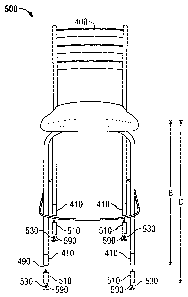
Figure 7 illustrates the reconfigured bar stool 400 of Figure 6 with a set of
additional leg extenders 510 attached to produce a second reconfigured bar
stool 500 in
accordance with an embodiment of the invention.
The additional leg extenders 510 engage the bottom surfaces 490 of the leg
extenders 410. End caps 530 engage the bottom surfaces 590 of the additional
leg
extenders 510 with screw threaded connections.
In operation, the reconfigured bar stool 400 of seat height B is provided. A
second reconfigured seat height C of the reconfigured bar stool 400 is
determined. One
21
CA 02519243 2003-11-12
additional leg extender 510 for each leg of the reconfigured bar stool 400 is
selected from
a set of additional leg extenders 510 of a length that will adjust the
reconfigured bar stool
400 from a reconfigured seat height B to a second reconfigured seat height of
C.
After the additional leg extenders 510 have been selected, a male threaded
connector on one end of each additional leg extender 510 is aligned with a
respective
female threaded connector located on the bottom surface of each of the leg
extenders 410.
Each additional leg extender 510 is threaded into the respective female
threaded
connector and rotated until a fixed stopping point is reached. The fixed
stopping point is
provided by a top surface of each additional leg extender 510 where the male
threaded
connector is attached to the additional leg extender 510. Consequently, the
seat height of
the reconfigured bar stool 400 is increased from a reconfigured seat height of
B to a
second reconfigured seat height of C with the additional leg extenders 510.
Because bottom surfaces 590 of the additional leg extenders 510 will be in
contact
with a floor surface when attached to the leg extenders 410, it may be
desirable to
provide a finished surface to the bottom surfaces 590 of the additional leg
extenders 510.
To provide a finished surface to the bottom surfaces 590 of the additional leg
extenders
510, end caps 530 may be engaged with threaded connections to the bottom
surfaces 590
of the additional leg extenders 510. A male threaded connector on the top of
each end
cap 530 is aligned with a respective female threaded connector located on the
bottom
surface 590 of each additional leg extender 510. Each end cap 530 is threaded
into the
respective female threaded connector and rotated until the top surface of each
end cap
530 is reached.
22
CA 02519243 2003-11-12
To produce a desired level of friction between the second reconfigured bar
stool
500 and a floor surface, the surface of the end caps 530 may be varied between
a low
friction surface and a high friction surface. For example, the surface of the
end caps 530
may be smooth to provide a low friction surface and rubber coated or roughened
to
provide a higher friction surface.
In the alternative, the additional leg extenders 510 may engage the bottom
surfaces 490 of the leg extenders 410 with wood pegs, dowels, glue, or other
suitable
means of engagement. Furthermore, the additional leg extenders 510 may include
finished bottom surfaces 590 with a surface that does not require the
attachment of end
caps 530.
In an alternative embodiment, additional sets of leg extenders 510 may be
continually engaged to previously added sets of leg extenders 410, 510 until a
desired bar
stool seat height has been obtained.
By attaching an additional set of leg extenders to already installed leg
extenders,
consumer costs rnay be reduced. By adding leg extenders to already installed
leg
extenders, a shorter leg extender may be used than if the already installed
leg extender is
entirely replaced with a new longer leg extender. A shorter leg extender may
include less
material, utilize less natural resources, and be less labor intensive to make
than a longer
extender. Resulting cost savings associated with shorter length leg extenders
may then be
passed on to consumers.
23
CA 02519243 2003-11-12
Furthermore, producing leg extenders that may be attached to other leg
extenders
allows for leg extenders to be manufactured and supplied in a modular format.
Rather
than produce leg extenders of a countless number of lengths to meet consumer
demand
for a countless number of desirable seat heights, a modular set of leg
extenders of a few
predetermined lengths may be produced. The modular set of leg extenders may
then be
combined in a plurality of combinations to extend the legs of a bar stool and
raise the seat
height of a bar stool to a plurality of desired seat heights.
For example, leg extenders in 1 inch, 3 inch, 6 inch and 12 inch lengths may
be
produced and included in a modular set of leg extenders. The modular set of
leg
extenders may then be used to increase the seat height of a bar stool from 24
inches to 27
inches by adding 3 inch leg extenders to each leg of the bar stool. The same
modular set
of leg extenders may also be used to raise the seat height of the 24 inch bar
stool by 4
inches even though a 4 inch leg extender is not included in the modular set.
The seat
height of the 24 inch bar stool may be increased by four inches by adding both
a 3 inch
leg extender and a 1 inch leg extender to each of the bar stool legs to raise
the bar stool
seat height to 28 inches.
Also, suppliers may be able to reduce inventory by using leg extenders that
may
be attached to other leg extenders. Rather than stock bar stools of a
countless number of
heights, a supplier may stock a base unit bar stool of a single height. Along
with the base
unit bar stool, a supplier may stock leg extenders of a few predetermined
lengths. Leg
extenders may then be added to the base unit bar stool in a plurality of
combinations to
produce a bar stool with a desired seat height.
24
CA 02519243 2003-11-12
For example, a first supplier that stocks a range of non-adjustable fixed
height bar
stools may have to stock at least one bar stool of a 24 inch seat height, at
least one bar
stool of a 30 inch seat height, and at least one bar stool of a 36 inch seat
height in order to
have at least one bar stool of each height on hand when a consumer places an
order.
A second supplier that stocks adjustable seat height bar stools may only have
to
stock a base unit bar stool of a 24 inch seat height and leg extenders with a
length of 6
inches and 12 inches. To meet consumer demand for a bar stool of a 30 inch
seat height
and a 36 inch seat height, the second supplier only has to attach the 6 inch
and 12 inch leg
extenders, respectively, to the base unit bar stool of a 24 inch seat height.
To further reduce inventory, the second supplier may forego stocking the 12
inch
leg extenders and only stock the 6 inch leg extenders. As before, to meet
consumer
demand for a bar stool of a 30 inch seat height, the second supplier would add
a 6 inch
leg extender to each leg of the 24 inch bar stool. However, to meet consumer
demand for
a bar stool with a 36 inch seat height, the second supplier would add two 6
inch leg
extenders to each leg of the 24 inch bar stool rather than a 12 inch leg
extender.
Consequently, the second supplier may further reduce inventory and storage
space
requirements by stocking a base unit bar stool and a modular set of leg
extenders that
may be combined to produce bar stools of various heights.
While the invention has been described with reference to certain embodiments,
it
will be understood by those skilled in the art that various changes may be
made and
equivalents may be substituted without departing from the scope of the
invention. In
addition, many modifications may be made to adapt a particular situation or
material to
CA 02519243 2003-11-12
the teachings of the invention without departing from its scope. Therefore, it
is intended
that the invention not be limited to the particular embodiment disclosed, but
that the
invention will include all embodiments falling within the scope of the
appended claims.
26