Note: Descriptions are shown in the official language in which they were submitted.
CA 02519283 2005-09-15
WO 2004/086084 PCT/FI2004/000174
1
ARRANGEMENT FOR COLLISION PREVENTION OF MINE VEHICLE
FIELD OF THE INVENTION
[0001] The invention relates to a method of preventing a mine vehi-
cle from colliding, the mine vehicle comprising at least: a movable carrier
that
may be driven in a first movement direction and in a second movement direc-
tion, at least one scanner, and a control system including at least a first
control
unit arranged on the carrier; the method comprising: determining for the mine
vehicle at least one safe area provided within an area between minimum dis-
tances and maximum distances determined with respect to the vehicle; scan-
ning the environment in front of the vehicle when driving the vehicle in one
movement direction; carrying out a first collision examination wherein the
safe
area in front of the vehicle is monitored, and issuing a collision warning mes-
sage if an obstacle is detected within the safe area.
[0002] The invention further relates to a mine vehicle comprising at
least: a movable carrier that may be driven in a first movement direction and
in
a second movement direction, at leasf one scanner, and a control system in-
cluding a~: least a first contr~I unit arranged ~n the carrier; and e~herein
at least
one scanner is configured to scan the environment in front of the vehicle in
order to detect obstacles; wherein at least one safe area defined by minimum
disfiances and maximum distances determined with respect to the vehicle is
determined in the control system; and which control system is configured to
monitor scanning results and to issue a collision warning message if an obsta-
cle is detected within the safe area in front of the vehicle.
BACKGROUND OF THE INVENTION
[0003] An unmanned mine vehicle may be driven in a mine auto-
matically along a predetermined route, controlled by a control system or,
alter-
natively, an operator may drive a vehicle in a remote-controlled manner from a
control room on the basis of camera observations. Since mine galleries are
usually of a limited size, a danger exists that while travelling along its
route, the
mine vehicle may collide with a mine wall or with other obstacles on its
route. It
is well known to equip an unmanned mine vehicle with a scanner and monitor
an area of a predetermined size in front of the vehicle. If an obstacle is de-
tected within this area, an alarm will be given and the vehicle stops automati-
cally. However, it is possible to provide the mine vehicles with only a
limited
CA 02519283 2005-09-15
WO 2004/086084 PCT/FI2004/000174
2
number of scanners, which means that depending on the structure and shapes
of the vehicle, there will still be some unmonitored "blind" areas in the
vehicle.
BRIEF DESCRIPTION OF THE INVENTION
[0004] An object of the invention is to provide a novel and improved
arrangement for collision prevention of a mine vehicle.
(0005] The method of the invention is characterized by determining
also at least one sideward safe area for the vehicle, determining an obstacle-
free route on the basis of scanning results, and determining points in a side-
ward direction of the vehicle to restrict the route; forming memory points on
the
basis of coordinates of the points restricting the route, and storing the
memory
points in the control system; and carrying out a second collision examination
wherein at least one sideward safe area of the vehicle is monitored, and issu-
ing a collision warning message if even one of the memory points resides
within the safe area being monitored.
(0005] The mine vehicle of the invention is characterized in that in
the control system, at least one safe area in a sideward direction of the
vehicle
is f~ad:her determined, that the control system allows several memory points
including their position information to be stored therein, and that the
control
system is configured to monitor at least one sideward safe area of the vehicle
and to issue a collision warning message if even one of the memory points
resides within the safe area being monitored.
(0007] An idea underlying the invention is that a mine vehicle in-
cludes at least one scanner configured to monitor the environment in front of
the mine vehicle when the mine vehicle is driven to one movement direction.
For a collision examination to be carried out in the control system of the
vehi-
cle, at least one safe area in a driving direction and at least one sideward
safe
area have been determined that have minimum distances and maximum dis-
tances of preplanned lengths from the vehicle. The locations on both sides of
the vehicle of the closest detection points in a sideward direction, i.e.
obsta-
cles, obtained as a result from scanning are stored as memory points in the
control system of the mine vehicle. The memory points determine an obstacle-
free route in to the control system, and the control system remembers the
shapes of the route at least for a section corresponding to the length of the
vehicle. In a collision examination to be carried out, it is thus first
checked that
the scanning does not detect an obstacle within a safe area in front of the ve-
CA 02519283 2005-09-15
WO 2004/086084 PCT/FI2004/000174
3
hicle. Secondly, the collision examination includes that the control system
monitors the vehicle and issues a collision warning message if even one of the
memory points resides within the sideward safe area being monitored.
[0008] An advantage of the invention is that the vehicle no longer
includes unmonitored sections as far as the collision examination is con-
cerned, even if the number of scanners were limited and even if the shapes
and structure of the mine vehicle were complex.
[0009] The idea underlying an embodiment of the invention is that a
collision examination is utilized in adjusting the control parameters of a
mine
vehicle. This enables potential oversteppings of the safe area due to steering
movements and the resulting disturbances to a production run to be avoided in
advance.
[0010] The idea underlying an embodiment of the invention is that
the control system includes a ring buffer wherein the coordinates of the mem-
ory points are stored. When the vehicle is driven in a first movement
direction,
memory points with respect to the movement of the vehicle that have been
produced by a first scanner are updated in the control system for a collision
e~zamination.
BRIEF DESCRIPTION OF THE DRAWINGS
[0~11~) The invention will be described in closer detail in the accom-
panying drawings, in which
[001] Figure 1 is a schematic side view showing a mine vehicle
according to the invention,
[0013] Figure 2 is a schematic top view showing a mine vehicle of
fihe invention,
[0014] Figure 3 is a schematic top view showing safe areas of a
mine vehicle of the invention, and
[0015] Figure 4 schematically shows how a control system of a ve-
hicle is provided with memory points of the invention.
[0016] For the sake of clarity, the figures show the invention in a
simplified manner. Like reference numerals identify like elements.
DETAILED DESCRIPTION OF THE INVENTION
[0017] Figure 1 shows a mine vehicle 1 which in this case is a load-
ing vehicle having a bucket at the front for carrying and loading mined
material.
Alternatively, the mine vehicle 1 may be e.g. a rock drilling rig or a
transport
CA 02519283 2005-09-15
WO 2004/086084 PCT/FI2004/000174
4
vehicle equipped with a platform. The mine vehicle 1 comprises a movable
carrier 2 arranged to be moved by a motor 3 through power transmission and
wheels. The mine vehicle 1 may also be equipped with a control system includ-
ing at least a first control unit 4 which is located on the carrier 2 and
which is
e.g. configured to control the actuators in the mine vehicle 1 in order to
steer
and use the vehicle. The unmanned mine vehicle 1 may further include a data
transfer unit 5 enabling the first control unit 4 to establish a data
transmission
connection 6 with a second control unit 7 external to the mine vehicle 1. The
second control unit 7 may be situated in a control room 8 possibly arranged
outside the mine. The control units 4 and 7 may be computers or correspond-
ing devices. The control system may further include navigation equipment 9 for
determining the position of the mine vehicle 1.
(0018] Figure 2 shows a mine vehicle 1, which may be arranged to
travel in a mine gallery 10 along a predetermined route 11. The route 11 may
be provided by driving the vehicle 1 in the mine manually while at the same
time storing the directions and travelled distances of the vehicle 1 as an
elec-
tronic map in the control system. For this purpose, the control system is pro-
vided v~,~ith an ~~, Y co~rdinate system describing the worlzing space ~f the
vehi-
cle 1. For the determination of a direction, the navigation equipment 9 may in-
clude e.g. a gyroscope or a corresponding device. The travelled distance, in
turn, may be measured e.g. from the power transmission or wheel of the vehi-
cle 1 in a manner known per se. In automatic drive, the control system may
control the mine vehicle 1 along the taught route 11. At necessary intervals,
the position may be checked to ensure that the vehicle 1 is on the route 11.
(0019, Alternatively, the unmanned mine vehicle 1 may be remote-
controlled manually e.g. from the control room 8. In such a case, the mine ve-
hicle 1 is equipped with at least one video camera 12, from which data is
deliv-
ered to an operator in the control room 8. The control room may be provided
with control means to enable the operator, based on a video image, to steer
the mine vehicle 1 along a desired route. The data transmission connection 6
between the control room 8 and the control unit 4 may be based e.g. on a ra-
dio telephone system.
(0020 Yet another alternative for controlling an unmanned mine ve-
hicle in a mine is to provide, in advance, the mine with appropriate reference
points 30, such as reflectors, light sources, sound sources or the like. The
CA 02519283 2005-09-15
WO 2004/086084 PCT/FI2004/000174
mine vehicle 1 then includes a scanner or a corresponding device to enable
the reference points 30 to be identified so as to position the vehicle 1.
[0021] According to the invention, the mine vehicle 1 is equipped
with a collision prevention system for ensuring that the vehicle dos not
collide
with external obstacles. The system includes at least one or more first scan-
ners 13 arranged at the front part of the vehicle 1 to enable the environment
in
front of the vehicle 1 to be scanned when the vehicle 1 is driven forward,
i.e. in
a first movement direction A. The system may further include at least one sec-
ond scanner 14 situated at the rear of the mine vehicle 1 to enable the space
behind the vehicle 1 to be scanned when the vehicle reverses, i.e. is driven
in
a second movement direction B. The number of both scanners 13 and 14 may
be more than one. The scanners may be laser scanners, ultrasound scanners
or corresponding devices that enable the space around the mine vehicle to be
examined.
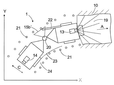
(0022] As can be seen in Figure 3, safe areas 15a to 15c may be
determined for a collision examination. The size of the safe areas 15a and 15c
in a driving direction may be different in the first movement direction A and
in
the second movement alirection B. Furthermore, the safe area 151a may be of a
different size in a sideward direction C than in the movement directions A and
B. The safe areas 15a to 15c comprise minimum distances 16 and maximum
distances 17 determined with rc spect to the vehicle 1. A minimum distance 16
may be determined according to the mine vehicle's 1 own dimensions, i.e. in
practice it depends on the external shapes and structure of the vehicle 1. The
use of minimum distances 16 enables false alarms due to the vehicle's 1 own
structures, such as movements of a boom, bucket, etc., to be prevented. The
maximum distances 17, in turn, determine the locations of the outer edges of
the safe areas 15a to 15c. When dimensioning the maximum distances 17, the
dimensions of mine galleries 10, the measures and strucfiure of the vehicle 1,
driving speed, circumstances and, further, safety-related aspects are taken
into
account. It is to be noted that the shapes of the boundaries formed by the
minimum distances 16 and the maximum distances 17 do not necessarily have
to be orthogonal but the boundaries may be determined point by point.
[0023] A first collision examination in practice takes place such that
when the vehicle 1 moves in the mine in the first movement direction A, the
environment in front of the vehicle 1 is scanned by the first scanner 13 and,
correspondingly, when driving in the second movement direction B, the envi-
CA 02519283 2005-09-15
WO 2004/086084 PCT/FI2004/000174
6
ronment is scanned by the second scanner 14. If, on the basis of the scanning,
the control system detects that an external obstacle 18 resides within the
safe
area 15a, the system issues a collision warning message. On the basis of the
collision warning message, the mine vehicle 1 may be stopped immediately
and further, the control room 8 may be notified of this. Obstacles located far-
ther than the maximum distance 17 of the safe area 15a do not cause a colli-
sion warning message since such obstacles do not cause a danger of collision.
A detection of an obstacle 18 within the safe area 15a may be confirmed by
several detections prior to issuing a collision warning message. This enables
false collision warning messages to be avoided.
[0024] Figure 4 illustrates how a collision examination may also be
carried out for the "blind" areas of a mine vehicle 1, i.e. areas uncovered by
a
detection area 19 of a scanner 13. It is not always possible to place a
sufficient
number of scanners on a carrier 2 so as to enable the entire vehicle 1 to be
included in the detection area 19 of the scanners. As far as collisions are
con-
earned, the critical point may occur e.g. at a middle joint 20 of the
articulated
vehicle 1 since during a turn, the strucfiures 22 of frame parts may extend
gaits
far in a sidcw~arc~ direction C of the vehicle 1 so that they may hit an
otastacle.
Furthermore, it may occur within a blind area that during a sharp turn, the
rear
wheels of the vehicle 1 strongly take a short cut and collide with an
obstacle.
This is illustrated in the figure by a br~ken line 23. The critical points of
the e~e-
hicle 1 may be provided with predetermined sideward safe areas of sues dif-
ferent than those provided at less critical points. Hence, for instance, the
sire
of a sideward safe area 15b' at the middle joint 20 may be larger than that re-
siding over a section of the front frame and the rear frame. Furthermore, the
sideward safe area may be larger on a first side of the vehicle than on a sec-
ond side thereof e.g. due to the shape of the route to be travelled.
[0025] For a "second" examination of the blind areas, the environ-
ment in front of the vehicle is scanned and the wall surfaces of a mine
gallery,
large pieces of rock and other solid objects relevant to a collision are
observed
on both sides of the vehicle 1 while driving. The coordinates of the detection
points closest in a sideward direction C are stored as memory points 21 in the
X, Y coordinate system of the control system, coordinate system describing the
working area of the vehicle 1. The memory points 21 define an obstacle-free
route for safe travel. Each memory point 21 is stored in the memory of the con-
trol system for at least until the vehicle 1 has completely passed the
particular
CA 02519283 2005-09-15
WO 2004/086084 PCT/FI2004/000174
7
memory point 21. In the second collision examination, the control system
checks that each sideward safe area 15b always resides within the route de-
fined by the memory points 21. In other words, it is ensured that no memory
point 21 resides within the sideward safe area 15b.
(0026] The arrangement of the invention may be implemented such
that the control system includes a "ring buffer" wherein the coordinates of
the
memory points 21 are stored. When the vehicle 1 is driven in a first movement
direction A, the memory points 21 produced by the first scanner 13 for the col-
lision examination with respect to the movement of the vehicle 1 are updated
in
the control system. Similarly, when reversing in a movement direction B, the
memory points 21 produced by the second scanner 14 are updated for a side-
ward collision examination.
(0027] Furthermore, it is possible to utilize the collision examination
in determining the steering parameters of a vehicle so as to avoid in advance
potential violations of the sideward safe areas. The control system may in ad-
vance simulate, by calculation, steering situations and, when necessary, alter
the steering parameters such that turning or another activity of the vehicle
never causes a situati~n wherein a part: of the vehicle is driven to the eda~e
of
the route defined by the memory points. This enables potential oversteppings
of the safe area due to steering movements and the resulting disturbances to a
producti~n run to be avoided in advance. It may be necessary for such an eaz-
amination to determine the turning angle of the vehicle 1. The control system
may calculate the turning angle e.g. on the basis of navigation data or,
alterna-
tively, a sensor may be provided in connection with the wheels or the middle
joint 20 to determine the turning angle. In addition, the control system may
de-
termine the positioning e.g. by means of direcfiion and distance measurements.
(002] The method of the invention may be executed by running a
computer program in a processor of a computer belonging to the control sys-
tem. The computer program implementing the method of the invention may be
stored in the memory of the control system or the program may be downloaded
into the computer from a memory means, such as a CD-ROM disc. Further-
more, the computer program may be downloaded from another computer e.g.
through an information network to a device belonging to the control system of
the mine vehicle.
(0029] Although only unmanned mine vehicles have been described
above, it is naturally also possible to apply the collision examination of
blind
CA 02519283 2005-09-15
WO 2004/086084 PCT/FI2004/000174
areas of the invention to completely common, manually controllable manned
vehicles. The invention enables the safety of a manual machine to be im-
proved and the work of an operator to be alleviated.
[0030 It is further possible that the safe areas 15a to 15c are up-
dated according to the location of the mine vehicle 1. On the basis of the up-
date, the dimensions and/or shape of the safe areas 15a to 15c in front of, on
the sides of and/or behind the vehicle may be changed. The side areas 15a to
15c may then be smaller when travelling through the narrow sections of a mine
and, on the other hand, they may be larger at points where the risk of
collision
is smaller. A possibility is that information on the size of the safe areas
15a to
15c is added to the route points of the route 11 travelled by the mine vehicle
1.
Another possibility is that the route 11 travelled by the mine vehicle 1 is
divided
into sections, i.e. segments, larger than a route point. Update information
may
be determined for the segments. When the mine vehicle 1 arrives at such a
route point or a segment, the control system may automatically update the safe
areas. It is relatively easy to add update information in connection evith the
route points and segmenfis and change it later. let another possibility is
that
the mine ~rehicle 1 i~9entifies or receives update inf~rma~tion on an
c~~ternal
identifier during driving e.g. when it arrives at a critical point as far as
safety is
concerned. The mine may be provided e.g. with remote-readable identifiers or
identifiers ~perating at a radio freguency that contain necessary update data.
[0~3'I~ The drawings and the related description are only intended
to illustrate the idea of the invention. The details of the invention may vary
within the scope of the claims.