Note: Descriptions are shown in the official language in which they were submitted.
CA 02519384 2005-09-16
Description
Process and hybrid reactor for the processing of residual waste
The invention relates to a process and a hybrid reactor for
processing waste substances, in particular residual waste in
accordance with the preambles of claims 1 and 21,
respectively.
A like process is known, e.g., from PCT/EP02/09855. One
problem in this waste processing process is the processing
of the process water used in the biological processing.
which is freighted with organic matter that must be removed
prior to introduction into a processing plant/sewer. It is
desired to manage the process water in a circuit, wherein
the process water fraction that is freed from organic matter
is returned to the biological processing as circuit water.
It was found, however, that in the conventional solutions it
is only possible with considerable expense in terms of
process technology to attain minimum concentrations of
organic matter constituents in the process water lower than
those required in order to smoothly carry out the process
and specified by regulations.
In view of this, it is the underlying object of the
invention to furnish a process and a hybrid reactor for
processing waste substances, wherein processing of the
process water is simplified in comparison with conventional
solutions.
In accordance with the invention, this object is achieved
through a process having the features of claim 1 and a
hybrid reactor having the features of claim 21.
Accordingly, the process contains a process water processing
step in which a denitrificaton of the process water freed
from organic matter takes place, so that this denitrified
1
CA 02519384 2005-09-16
process water may again be supplied to the process or to a
further processing.
Such denitrificaton is preferably carried out in a stripper
means comprising a stripper column into which air is blown
in in a counter-flow to the injected process water, and
which is followed downstream by a catalyst column for
converting the ammonia gas into nitrogen.
Another alternative provides a stripper means comprising a
stripper column into which saturated vapor is injected in a
counter-flow to the injected process water, and which is
followed downstream by a cooler for condensing the exiting
vapor mixture.
Optionally it is possible to combine several stripper means
of one or several types.
The efficiency of the process may be improved further by
adding lye upstream of the stripper means. As a result of
this lye, the pH value of the process water is raised and
ammonia gas is dissolved in the process water.
By the process water processing in accordance with the
invention it is possible to treat turbid water or water
discharged from a percolation, a pulper, or an anaerobic
process. Previously it had been necessary to individually
adapt the process water processing method to the type of the
biological processing of the waste substance.
The proportion of solids in the process water may be further
reduced by ultrafiltration. This ultrafiltration may have
associated a precipitation of chlorides, phosphates, etc.
The biological process water processing preferably is
carried out with the aid of a hybrid reactor having a sludge
discharge device at its bottom, and means for destroying a
forming surface scum at its head.
2
CA 02519384 2005-09-16
For a desulfurization of the forming biogas, air or oxygen
may be injected into the head of the reactor.
In order to improve the metabolization process, the hybrid
reactor may be provided with means for pressing in gas
whereby the forming bed of sludge is periodically subjected
to a pressure.
At particular process conditions it is advantageous if a
part of the solids is separated off by a flotation.
In particular it is advantageous if the process water
freighted with organic matter is subjected to sand washing
in the hybrid reactor prior to the processing.
Sand washing may be followed by sand sedimentation and
precipitation means in order to filter off the remaining
micro-fine sand and to not carry out a precipitation of
salts, inert substances, etc. in the hybrid reactor.
Solids, floating matter, and fibrous substances may be
separated off in a sifting stage.
The physico-chemical processing (PCP) subsequent to
processing of the process water in the hybrid reactor may
comprise a reverse osmosis for separating turbid water,
salts, etc. from the process water.
In the following, preferred embodiments of the invention
shall be explained in more detail by referring to schematic
representations, wherein:
Fig. 1 shows a basic model of a process for aerobic residual
waste processing including a percolation or pulper plant,
Fig. 2 shows a solids and water treatment in the case of
percolation or pulping with subsequent separating steps,
Fig. 3 shows a first embodiment of a PCP plant,
3
CA 02519384 2005-09-16
Fig. 3.1 shows a sequential arrangement of two stripper
columns after the first PCP waste water treatment,
Fig. 4 shows a second embodiment of a PCP plant,
Fig. 5 shows a combination of the concepts in accordance
with Figs. 3 and 4,
Fig. 6 is an overall view of a model process for residual
waste processing including a hybrid reactor,
Fig. 7 shows a hybrid reactor with upstream sand
sedimentation and a precipitation reactor,
Fig. 8 is a partial view of a model process for anaerobic
residual waste processing including a fermentation plant,
and
Fig. 9 shows a variant of the process represented in Fig. 2.
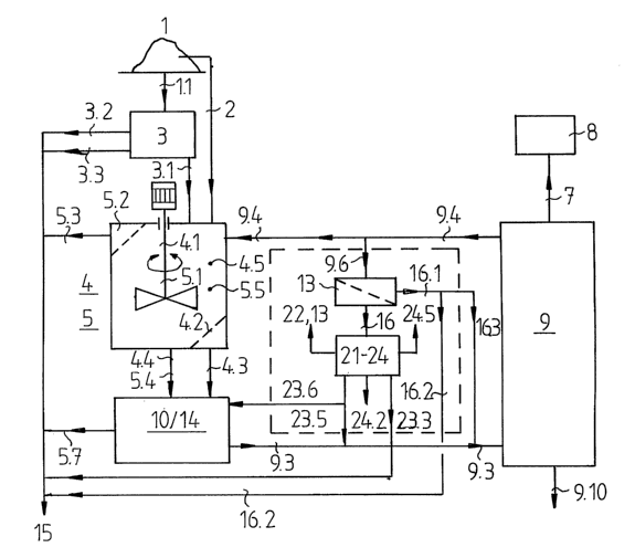
Fig. 1 shows a model process for the aerobic processing of
polluted waste substances having in particular a dry
substance content (DS content) of 50% to 650, such as, e.g.,
residual waste, catering wastes, wastes from the food
industry, vegetables, and other replenishing organic waste
substances, sewage and fermentation sludge, and biological
residues from the manufacture of beverages, such as mashes.
The organically charged substances 1 are supplied either
through a direct supply 2 or via an upstream mechanical
processing plant 3 to a percolation plant 4 or to a pulper
plant 5.
Mechanical processing 3 includes the working steps of
sifting, sorting and comminuting, wherein the sifting
fraction 3.1 is preferably supplied to a percolation plant 4
for particle sizes of 50 mm to 250 mm and preferably to a
pulper plant 5 for particle sizes of >250 mm. In the case of
a sifting fraction 3.1 having a maximum particle size of
about 50 mm, it is preferably supplied to a dry fermentation
plant 6 (Fig. 8). In order to separate out material having a
high calorific value and large-surface material such as
sheets, cartons and paper, a screen overflow 3.2 is
provided. In the same way, means 3.3 for sifting and sorting
4
CA 02519384 2005-09-16
steps are provided in order to eliminate interfering
materials such as, e.g., machine parts, wooden beams, FE and
NE metals, as well as inert substances and minerals of
various particle sizes. The eliminated solids are subjected
to a further treatment 15 or utilization depending on their
properties. Thus it is possible, e.g., to return the metal-
containing solids to the steel-processing industry, and the
wood-type solids to the paper industry, and to store the
mineral substances or minerals for deposition on a dump.
The percolation plant 4 may be a percolation plant in
accordance with German patent application DE 196 48 731 A1,
in which the organic constituents of a waste fraction are
washed out in a percolator, and the residue is burnt, for
instance, following drying. Moreover it is possible to
employ a box percolation plant comprising a horizontally
arranged, box-type or cylindrical percolator as disclosed,
e.g., in WO 97/27158, as well as a boiling percolation plant
in accordance with German patent application
DE 101 42 906 Al, according to which a percolator is
operated in the boiling range of the process water.
Inside the percolator or receptacle 4.5 a rotary mechanical
stirring mechanism 4.1 for circulating and mixing heap
material is arranged. Leaching water 9.4 is introduced into
the head of the receptacle 4.5, whereby the organic
substances are washed out from the heap material, and which
is then drawn off in the form of organically highly charged
discharge water 4.3 at the foot of the receptacle 4.5. The
outlet opening is arranged downstream of a sieve bottom 4.2
so as to prevent solids from exiting.
The solids 4.4 freed from the organic matter are taken out
through extraction means from the receptacle 4.5 and
supplied to separating steps (Figs. 2, 9) including a
classing press 10 as well as a sink/float separation 14. The
discharge water 4.3 is supplied directly to the sink/float
separation 14.
5
CA 02519384 2005-09-16
The average DS content in the receptacle 4.5 is determined
by the quantity of supplied washing water 9.4 and of
organically highly charged discharge water 4.3, as well as
the dwell time or stay time in the receptacle 4.5, and
amounts to about 20% to 350. The stay time is, in accordance
with the plant, 2 h to 50 h.
The alternatively usable pulper plant 5 comprises a pulper
vessel 5.5 in which a high-velocity stirring mechanism 5.1.
for dragging apart the supplied organically charged
substances 1 is arranged. The organic matter in the heap
material is solubilized by diluting with washing water 9.4
supplied on the head side and by shear forces induced by the
stirring mechanism 5.1..
Large-surface light-density materials 5.3 are discharged for
further treatment 15 via mechanical discharge means 5.2
situated on top. The discharge means 5.2 have a fork-type
construction and are presently represented as a screen. The
solubilized organic matter is discharged with the solids 5.4
through bottom-side extraction means and the classing press
10 and thus supplied to the following sink/float separation
14.
The DS content in the pulper vessel 5.5 is adjusted to 5% to
loo by supplying the washing water 9.4. The solubilization
and separation step is about lh to 3h in the pulper plant 5.
The substance flows 5.7 and 9.3 occurring in the classing
press 10 and in the sink/float separation 14 are supplied as
a residual flow 5.7 to the further treatment 15, and the
organically highly charged liquid 9.3 freed from the solids
is supplied to a biogas plant 9 (Figs. 1, 6, 7) in
accordance with the invention.
Thus it is possible, for instance, to obtain from the
residual flows 5.7 FE and NE metals or utilizable mineral
6
CA 02519384 2005-09-16
substances and minerals for a deposition on dumps in
accordance with particular dumping criteria, e.g., Z2.
Moreover it is possible to filter out mixtures rich in
organic matter for a further biological treatment such as
composting, for instance until an equivalence certification
or criteria for dumping on specially implemented dumps are
satisfied, and to filter out problem substances for their
disposal.
The liquid 9.3 charged with organic matter is supplied to a
biogas plant 9 (Figs. 1, 6, 7) for anaerobic decomposition.
There the liquid 9.3 is de-freighted by converting the
organic matter proportion by means of methane bacteria, and
supplied to a biogas combustion 8 for energy generation by
means of a gas generation line 7.
The fermentation water de-freighted of the organic matter
exits from the biogas plant 9 and is supplied, in the form
of absorptive washing water 9.4, to the washing processes 4,
5 as process water.
A partial flow 9.6 of the washing water 9.4 is supplied to
an ultrafiltration 13, and/or a decanter and/or a screen
belt press or a mechanical edge filter. Ein solids/water
mixture 16.1 thus engendered is supplied to the further
treatment 15 in the form of a press cake 16.2 and may partly
be admixed to the liquid 9.3 charged with organic matter
from the sink/float separation 14 as inoculating sludge
16.3. Press water 16 occurring in the ultrafiltration 13 is
supplied to a physico-chemical processing plant (PCP plant)
21, 22, 23, 24 in accordance with the invention for a
denitrificaton.
The press water 16 is freed from nitrogen in the PCP plant
21, 22, 23, 24. This engenders substance flows that are
either supplied as salt-free water or permeate 23.5 to the
liquid 9.3 charged with organic matter, or to the sink/float
separation 14 as purified, salt-free operating water 23.6.
7
CA 02519384 2005-09-16
Other occurring substance flows, such as ammonia water
concentrate 24.2, are stored and used, e.g., for the
denitrificaton of large-scale combustion plants such as
thermal power plants and waste incineration plants.
Occurring solids 23.3 are supplied to the further treatment
15. The waste air 22.13 charged with nitrogen that is
present after the PCP and purified water vapor 24.5 are
discharged into the environment. A detailed explanation of
the denitrificaton in accordance with the invention with an
upstream ultrafiltration 13 will be given by referring to
Figs. 3, 3.1, 4 and 5.
Fig. 2 schematically shows a process flow in a percolation
or a pulper plant 4, 5 including the downstream separating
steps 10, 14 of Fig. 1.
Basically the path of the solids flows 4.4, 5.4 downstream
of the percolation plant 4 and the pulper plant 5 is
identical. The essential difference is that the percolation
plant 4 need not be arranged downstream from the sink/float
separation 14 in order to supply the substance flow 4.3 to
the biogas plant 9, whereas in the pulper plant 5 the
sink/float separation 14 is necessary in order to filter the
pulp (solid) from the substance flow 5.4. Hereinafter the
sink/float separation 14 is, however, interposed in either
process for the purpose of simplification.
It is another difference that discharge water 4.3 to be
supplied to the sink/float separation 14 does not occur in
the pulper plant 5, but instead light-density materials 5.3
are created that are supplied to the further treatment 15.
Following percolation in the percolator 4, the percolated
solid 4.4 is supplied to the classing press 10, and the
discharge water 4.3 to the combined flotation or sink/float
separation 14. In the classing press 10 the press cake 12 is
separated from the waste water 10.1. and supplied to the
further treatment 15.
8
CA 02519384 2005-09-16
In the pulper process 4, the light-density materials 5.3 are
supplied to the further treatment 15, and the solids 5.5 are
also supplied to the classing press 10.
The waste water 10.1 of the classing press 10 that is freed
from rough solids is supplied to a mixer 14.1.5 in which it
is mixed with air by means of a ventilator 14.1.4 and
subsequently injected at a slight superpressure via bottom-
side injection means 14.1.6 into a separation tank 14.1 of
the sink/float separation 14. As a result of enriching the
waste water 10.1 with air and blowing in at superpressure,
the reparability and the separation rate are enhanced
considerably in comparison with a known pressure relief
flotation.
The discharge water 4.3 of the percolator 4 charged with
organic matter is supplied on the head side to the
separation tank 14.1. where it mixes with the waste water
10.1, and floating matter 14.1.1 and sinking matter 14.1.2
separate out from this water mixture.
The floating matter 14.1.1 floats to the surface to form a
scum of floating matter. By means of mechanical means 14.1.3
situated on top, the floating matter 14.1.1 is withdrawn and
supplied to the classing press 10 for additional dewatering
via a conveying line 14.1.7.
The.sinking matter 14.1.2 such as, e.g., sand, pebbles and
metal parts, sink to the bottom in the separation tank 14.1
and are withdrawn by means of discharge and transport means
14.1.8. Depending on the purpose of use, they are supplied
to a further treatment 15 via a conveying line 14.1.9 or
conducted via a conveying line 14.1.10 to a washing stage
14.2 for separating off the sand or the inert substances.
In the washing stage 14.2., the sand intended for use as a
construction material, e.g., for road construction, is free
9
CA 02519384 2005-09-16
from the organic matter by washing out in accordance with
deposition regulation Z2. In an advantageously cylindrical
and erect vessel having a conical bottom, the sinking matter
or sand/liquid mixture 14.1.2 are introduced into the vessel
on the head side via the conveying line 14.1.10 and rinsed
by means of the purified operating water 23.6 of the PCP
plant 21, 22, 23, 24 introduced via introduction means
14.2.6. In order to reduce the consumption of operating
water 23.6, air may be admixed in the mixer 14.1.5 to the
operating water 23.6 with the aid of a ventilator 14.1.4.
The air and the operating water 23.6 may be introduced into
the vessel continuously or intermittently, as well as
separately from each other.
Here it has been found to be advantageous if a preferably
slow-moving stirring mechanism (not shown) is used in the
vessel in order to introduce shear forces into the
sand/liquid mixture to thus facilitate the separation of the
organic matter from the sand.
The sand 14.2.2 sinks down in the vessel while the organic
constituents 14.2 float to the surface and are discharged as
an organic matter/operating water mixture 14.2.3. The sand
freed from the organic matter 14.2.9 is discharged on the
bottom side via discharge and conveying means 14.2.8, and
used as a construction material or added to the press cake
12 and subjected to the further treatment 15.
The organically highly charged waste water 14.1.11 from the
separation tank 14.1. is conducted to a sifting stage 14.3.
In the sifting stage 14.3 the two liquid flows 14.1.11,
14.2.3 charged with organic matter are introduced while
mixed with each other via an introduction line 14.2.7. The
sifting stage 14.3 preferably comprises a drum screen or
oscillating screen 14.3.1 lined on the inside and having a
mesh size of about 0.5 mm to 1.5 mm, so that the fibers,
residual matter, and plastics particles contained in the
CA 02519384 2005-09-16
liquid flow 14.2.7 are separated out. The pasty mass 14.2.10
thus created is discharged and supplied to the classing
press 10 for dewatering via conveyor means 14.2.4 and
conveying lines 14.2.5, 14,2,6. As an alternative, the pasty
mass 14.2.10 may again be supplied to the percolation plant
4 via conveying lines 14.2.5, 14.2.11.
The organically highly charged liquid 9.3 passing the screen
14.3.1 and accumulating at the bottom of the sink/float
separation 14 is in accordance with Fig. 1 supplied to the
biogas plant 9, wherein the fermentation water de-freighted
of the organic matter is again supplied to the biogas plant
9 on the one hand as an absorptive washing water 9.4 of the
percolation plant 4 or of the pulper plant 5, and on the
other hand passes through the ultrafiltration 13 and the PCP
plant 21, 22, 23, 2 as a partial flow 9.6.
Fig. 3 shows in detail a preferred PCP plant in accordance
with the invention. The press water 16 of the
ultrafiltration 13 is heated to the required process
temperature in a heat exchanger 17. The heated press water
18 is admixed with a lye 19 in order to raise the pH value,
so that ammonia is present in the press water 18 in a
dissolved form. The mixed water 20 is treated in a stripper
means 22 for separating ammonia gas from the water with an
efficiency of about 90o by means of pre-heated air 22.2.
The stripper means 22 comprise a stripper column 22.1 into
which the mixed water 20 is introduced in an upper area
through spraying means 22.4. The mixed water 20 introduced
by spraying flows downwards in the stripper column 22.1.,
wherein a filling body packing 22.6 is introduced into the
stripper column 22.1 so as to enlarge the exchange surface.
At the same time the mixed water 22 is passed through in a
counter-flow by the heated air 22.2 introduced via a fresh
air ventilator. Ideally the air 22.2 is heated to the same
temperature as the mixed water 20 with the aid of a heat
exchanger 22.7. The ammonia contained in the mixed water 20
11
CA 02519384 2005-09-16
is released by the pre-heated air conducted in a counter-
flow and exits from the stripper column 22.1 as ammonia-
laden waste air 22.3. The water 22.5 freed from the ammonia
gathers at the bottom of the stripper column 22.1 and is
supplied to a reverse osmosis 23. In order to achieve a
stripping effect of about 900, the pH of the mixed water 20
is advantageously raised to >10, and the temperature of the
mixed water 20 and of the heated air 22.2 is adjusted to
60 °C.
The waste air 22.3 is supplied to a catalyst column 22.8 in
which the ammonia present in the form of a gas is decomposed
and reduced to atmospheric nitrogen, and the hydrogen is
oxidized into water. The catalyst column 22.8 is at the
beginning pre-heated to the required operating temperature
by means of a heating 22.9. If a sufficient quantity of
ammonia is present in the waste air 22.3, the further
process may unfold autothermally, i. e., the pollutants
contained in the waste air 22.3 supply the required reaction
heat. This is satisfied if the ammonia content in the press
water 16 is at least about 2000 mg/1. If the ammonia content
drops below this approximate limit value of 2000 mg/l, heat
energy must be supplied.
The waste air 22.3 exits from the catalyst column 22.8 in
the form of residual air 22.11 that is saturated with water
vapor and charged with nitrogen. The residual air 22.11 is
cooled in a cooler or condenser 22.12 and downstream from
the latter discharged to the environment in the form of
waste air 22.13 charged with nitrogen, N2.
A proportion that is freed from ammonia exits from the
catalyst column 22.8 in the form of a condensate 22.10 that
is supplied to the reverse osmosis 23.
In the reverse osmosis 23, pollutants present in the water
22.5 of the stripper column 22.1 and in the condensate 22.10
of the catalyst column 22.8 are pressed through diaphragms
12
CA 02519384 2005-09-16
inside a receptacle 23.1 by molecular diaphragm techniques
with the aid of high-pressure means 23.2. The water
molecules exit from the receptacle 23.1 in the form of a so-
called permeate 23.5 practically free from salt. This
permeate 23.5 may, for example, be partly used as the
operating water 23.6 in the above described washing stage
14.2 or be admixed to the liquid 9.3 highly charged with
organic matter that is introduced into the biogas plant 9
(Figs. 1 and 6). The salt molecules and other pollutions
exit from the receptacle 23.1 together with sewage 23.3 in
the form of a concentrate 23.4. This concentrate 23.4 may
subsequently be dried, e.g., by evaporation in a vacuum-
boiling drying, and then supplied to the further treatment
15.
In accordance with Fig. 3.1. it is also possible to
sequentially arrange several stripper columns 22. When two
stripper columns 22, 22' are arranged sequentially, it is
possible to reduce the ammonia load by 99%.
The mixed water 20 charged with ammonia is supplied to the
first stripper column 22.1, and following a first
purification step extracted in the form of water 22.5 that
is freed from ammonia up to 900. With the aid of a pump
22.5.1 this water 22.5 is supplied to the second stripper
column 22.1' and there subjected to a further purification
step. The water 22.5' freed from ammonia up to 990
subsequently arrives at the reverse osmosis 23. The waste
air 22.3, 22.3' charged with ammonia of the two stripper
columns 22.1, 22.1' is supplied to a catalyst column 22.8 as
described above.
Fig. 4 shows a basic model of another embodiment of a PCP
plant 21 for processing press water 16 having an ammonia
content of about 2000 mg/1 at the most, a chloride content
of about 5000 mg/1, and a chemical oxygen demand (COD
content) of about 2000 mg/l.
13
CA 02519384 2005-09-16
The press water 16 of the ultrafiltration 13 is heated in a
heat exchanger 17 and supplied on the head side to a
stripper column 21.1 in the form of heated mixed water 20
with an admixture of a lye 19 so as to raise the pH value.
The mixed water 20 is sprayed in the stripper column 21.1
with the aid of spraying means 21.4 and moves downwards,
while its substance exchange surface is enlarged with the
aid of a filling body packing 21.6. At the same time,
saturated vapor 21.2 generated, e.g., by means of a steam
generator or of a waste vapor generator 21.7, is injected in
a counter-flow. By the introduction of this vapor it is
possible to reduce the ammonia in the mixed water 20 by up
to 990. The ammonia is washed out from the mixed water 20,
and the charged waste vapor 21.3 is supplied to cooling
means 24 including a cooling or condenser column 24.1. The
ammonia-laden waste vapor 21.3 is cooled, whereby an
ammonia/water concentrate NH40H 24.2 including about 250 of
ammonia is obtained. This concentrate 24.2 is received in a
storage 24.3 and may - as mentioned under Fig. 1 - be used
for the denitrificaton of large-scale combustion plants 24.4
such as thermal power plants and waste incineration plants.
In this case the ammonia is sprayed into the combustion and
thus suppresses the formation of NOx.
As an alternative, the concentrate 24.2 may also be dried,
e.g. by evaporation in a vacuum-boiling drying, and
subsequently be supplied to the further treatment 15.
The water vapor 24.5 separated out by condensation and
substantially free from ammonia is discharged to the
environment.
The water 21.5 freed from ammonia is extracted from the
stripper column 21.1 on the bottom side and supplied to the
above mentioned reverse osmosis 23.
Fig. 5 shows a combination of the basic models of Figs. 3
and 4, wherein the ammonia load in the waste water is also
14
CA 02519384 2005-09-16
reduced by up to 99%. In addition the occurring ammonia
waste water concentrate 24.2 is reduced to a quantity that
does not pose any problems in terms of disposal.
The combination includes two stripper means 22, 21 arranged
in series. In the first stripper means 22 - as is known from
Fig. 3 - heated air 21.2 is blown into the stripper column
21.1, and in the second stripper means 22 - as is known from
Fig. 4 - a saturated vapor 21.2 is injected into the
stripper column 21.1.
The waste air 22.3 charged with ammonia of the first
stripper column 22.1 is supplied to a stripper catalyst
22.8. The water 22.5 freed from ammonia is mixed with the
condensate 21.10 of the stripper catalyst 22.8 and supplied
to the stripper column 21.1 of the second stripper means 21
in the form of mixed water 20.1 with the aid of a pump
22.5.1.
The waste vapor 21.3 charged with ammonia from the second
stripper column 21.1 is in accordance with the above
description supplied to the cooling means 24 and condensed
there. The water 21.5 charged with ammonia is in the above
described manner supplied to the reverse osmosis 23.
Fig. 6 shows a model process of a residual waste processing
including essentially a percolation plant 4 or a pulper
plant 5 and a substances separation and processing plant 10,
14 for the liquid 9.3 that occurs in the washing processes
4, 5, is enriched with dissolved organic matter and residual
raw materials, and supplied to a hybrid reactor 9 in
accordance with the invention.
In known biogas plants the liquid 9.3 is fermented in fully
mixed and one- to two-stage stirring vessel reactor, wherein
the organic matter is converted into biogas. As a stirring
mechanism customarily a mechanical agitating system or a
gas-injection circulation system is used. The dwell time of
CA 02519384 2005-09-16
the liquid 9.3 in a like stirring vessel reactor is about 18
to 24 days.
In contrast with these known solutions, a dwell time of
about 2 days to 4 days is sufficient in the hybrid reactor 9
in accordance with the invention. Moreover it is
advantageous in the solution of the invention that by the
pre-treatment stage having the form of the sink/float
separation 14 (cf. Fig. 2) the liquid 9.3 discharged from
the pulper plant 5 may also be supplied to the hybrid
reactor 9, for this pre-treatment stage 14 sufficiently
filters out the solids from the liquid 9.3.
The hybrid reactor 9 comprises an insulated cylindrical
receptacle 9.1. On the bottom side the pre-treated liquid
9.3 is injected through injection means 9.3.3 across the
cross-section of the receptacle 9.1 such that an approximate
rising velocity of 2 m/h results. The organic constituents
solved out from the injected liquid 9.3.2 by means of
methane bacteria sink downwards in the hybrid reactor 9 and
there form a bed of sludge 9.2.1. The bed of sludge 9.2.1
serves as a fermentation stage and reaction bed for
precipitating, e.g., inert substances, chlorides, and
phosphates. By means of sludge discharge means 9.8 a
discharge sludge 9.10 including an admixture of precipitated
inert substances and salts is discharged from the receptacle
9.1.. Precipitation is supported with the aid of a
precipitation agent 9.7 that is admixed to the liquid 9.3
prior to entry into the hybrid reactor 9.
In order to support the conversion of substances, i. e., for
an enhanced decomposition of methane gas and for enhanced
purification of the liquid 9.3.2 charged with organic
matter, the methane bacteria are arranged in a filling body
packing or in a solid bed 9.2 consisting of a bulk material
or block elements. The enhancement of the substance
conversion is predominantly brought about by an increase of
the reaction surfaces and an immobilization of the active
16
CA 02519384 2005-09-16
bacteria sludge. The reaction surfaces amount to
approximately 200 m2/m3 to 300 m2/m3.
The sludge discharge means 9.8. comprise at least one
sliding floor means 9.8.1 including scraping elements and at
least one worm conveyor 9.8.3. The sliding floor means 9.8.1
are represented as a piston rod of a hydraulic
cylinder/piston unit 9.8.2 on which the scraping elements
are mounted. In each extension movement of the piston rod,
i. e., a movement to the right in Fig. 6, the discharge
sludge 9.10 is conveyed to the worm conveyor 9.8.3. By means
of a valve 9.8.4 an outlet from the worm conveyor 9.8.3 may
be closed.
The liquid freed from the organic constituents is extracted
overhead from the receptacle 9.1 and supplied in the form of
the washing water 9.4 to the percolation plant 4 or to the
pulper plant 5, as well as in the form of a partial flow 9.6
to the ultrafiltration 13 with a subsequent PCP plant 21,
22, 23 ,24.
In order to avoid the formation of a surface scum of
floating matter 9.11.1, a horizontal stirring mechanism 9.11
is provided closely underneath the surface of the injected
liquid 9.3.2 accumulated in the receptacle 9.1. The
horizontal stirring mechanism 9.11 may be replaced with a
vertical stirring mechanism or the like.
In order to subject the bed of sludge 9.2.1 and the filling
body packing 9.2 to shear forces, gas 9.14.2 is periodically
injected by means of a ventilator or a compressor 9.15 via a
tubing 9.14 and gas injection nozzles 9.14.1. Preferably
this gas is taken from the biogas supplied to the biogas
combustion. Such an injection of gas has the effect that the
formation of channels in the filling body packing 9.2 is
suppressed and old, dead bacteria sludge is solved out from
the filling body packing 9.2 to either float to the surface
as a floating matter 9.11.1 or be discharged together with
7. 7
CA 02519384 2005-09-16
the discharge sludge 9.10 as a sinking matter depending on
its weight.
In order to withdraw sulfur from the biogas, a
desulfurization chamber 9.12 is provided in the head, into
which air or oxygen 9.13.2 is injected by means of a
ventilator 9.13 that includes a throughput control. In order
to prevent explosions of the biogas/air mixture, the
proportion of air is 2.Oo at the most. Thanks to this
injection of air, the sulfur in the biogas is precipitated
in the form of elemental sulfur 9.13.1 and forms the surface
scum 9.11.1 on the surface. The elemental sulfur 9.13.1 is
not soluble any more and sinks downwards in the hybrid
reactor 9, where it is discharged together with the
discharge sludge 9.10.
A partial flow 9.6 is branched off from the washing water
9.4 and supplied to the ultrafiltration 13. Following the
ultrafiltration 13, the press water 16 having an ammonia
content of about 1000 mg/1 to 3000 mg/1 is supplied to the
PCP plant 21, 22, 23, 24, denitrified there in accordance
with the preceding description (Figs. 3, 3.1. 4 and 5), and
again admixed to the charged liquid 9.3 in the form of a
denitrified operating water 23.6.
A solids/water mixture 16.1 having a DS content of about 40
to 80, which occurs in the ultrafiltration 13, is supplied
to the further treatment 15 in the form of a press cake 16.2
and/or also admixed to the liquid 9.3 that is highly charged
with organic matter, as an inoculating sludge 16.3 for the
hybrid reactor 9.
Moreover the partial flow 9.6 serves as circuit water 9.5
for adjusting the operating temperature. The circuit water
9.5 is heated in a heat exchanger 9.5.1 and mixed with the
organic matter-laden liquid 9.3.
18
CA 02519384 2005-09-16
Fig. 7 shows an alternative basic model of a process in
accordance with Figs. 1 and 6 for the processing of residual
waste, comprising a biogas plant 9' with an upstream sand
settling and precipitation reactor 25. The upstream
arrangement of a like reactor 25 has the advantage that the
sand settling and precipitation process does not unfold in
the hybrid reactor 9 so that it is possible to do away with
sludge discharge means 9.8 that are costly in terms of
construction.
It was found in trials that the sand settling time is about
1 h, and the precipitation time 5 min at the most. Thus the
size and geometry of the receptacle 25.1 are designed for a
stay time of at least one hour.
The sand settling and precipitation reactor 25 comprises a
cylindrical receptacle 25.1 including a submersible wall
25.2 for the forced introduction of a liquid flow into the
receptacle 25.1. The submersible wall 25.2 extends from a
receptacle cover in the direction of a bottom-side, worm-
type discharge means 25.4 wherein a passage for the liquid
flow is formed between the submersible wall 25.2 and the
discharge means 25.4.
The liquid 9.3 charged with organic matter is mixed with a
precipitation agent 9.7 and supplied to the receptacle 25.1.
The liquid 9.3 flows around the submersible wall 25.2, with
the sand and the precipitated products such as, e.g.,
chlorides and phosphates accumulating on the receptacle
bottom and being discarded by the discharge means 25.4 in
the form of discharge sludge 9.10.
The liquid 9.3.1 freed from the sand and the precipitated
products is extracted on the head side from the receptacle
25.1 and supplied to the hybrid reactor 9 for the further
processing as described above.
19
CA 02519384 2005-09-16
Instead of the partition wall 25.2 it is also possible to
use mixing means or combine the latter with the partition
wall 25.2. The mixing means may be particularly advantageous
with heavy metals, for the latter require a longer contact
period. In addition a mixing mechanism may be provided in
the supply to the receptacle 25.1.
Fig. 8 shows an alternative for the waste processing
including a percolation plant 4 or a pulper plant 5. The
process represented there is based on the use of a dry
fermentation plant 6. Accordingly this model process does
not include a hybrid reactor 9 in accordance with the
invention.
The fermentation plant 6 comprises a fermentation receptacle
for carrying out a fermentation process with exclusion of
air, i. e., anaerobic fermentation. Such a fermentation
receptacle is used, e.g., in systems of the Swiss company
Kompogas AG (www.kompogas.ch), the Austrian Baustoff and
Recycling Verband (BRV, www.brv.at), Dranko, and the French
company Valorga Int. SAS (www.steinmuller-valorga.fr).
In the case of Kompogas and BRV, the sifting fraction or
fresh waste 3.1 is introduced into the mechanical processing
3 of the organically charged substances 1 while admixing
inoculation material 6.4 taken from the fermentation process
by inoculating it with anaerobic bacteria, and after
dilution with process water 10.2 is introduced into the
fermentation receptacle by means of a pump and conveyor
means 6.3 via a head-side feed line 6.5. The fermenter
contents 6.7 are periodically circulated with the aid of a
stirring mechanism 6.1 and transported to an outlet at the
bottom by a mechanical effect. The process heat is
maintained with the aid of an external jacket heating (not
shown) and a heat exchanger in the feed line 6.5 (not
shown) .
CA 02519384 2005-09-16
In Dranko and Valorga, just like in the plants according to
Kompogas and BRV, the fresh waste 3.1 is inoculated and
diluted by admixing the inoculation material 6.4. and
process water 10.2., and introduced via the feed line 6.5
into the fermentation receptacle and circulated by means of
pump and conveyor means 6.3.
Other than in the case of Kompogas and BRV, the fermentation
receptacle 6 in Dranko/Valorga has the form of a
cylindrical, erect element in steel or concrete construction
while not having any mechanical stirring mechanism in
interior. In Dranko, circulation is performed by the pump
and conveyor means 6.3 exclusively. In Valorga, circulation
is performed with the aid of a gas injection system with
injection lances 6.2 near the bottom whereby the fermenter
contents 6.7 are subjected to pressure pulses of 8 bar.
The process temperature in Dranko and Valorga is adjusted by
means of an external jacket heating and a heat exchanger in
the pump and conveyor means 6.3 and the feed line 6.5,
respectively, as well as direct blowing in of steam into the
fresh waste 3.1.
The anaerobic biogas generation from the fermentation
process in accordance with the fermentation plant 6 takes
place in the fermentation receptacle, wherein the generated
biogas is conducted overhead through the gas generation line
7 to the gas combustion 8.
From this biogas having a methane content of about 55% to
65%, heat and electricity may be generated with the aid of a
block-type thermal power station. As an alternative, the
biogas may be supplied to a direct combustion, or by a
special gas processing with methane enrichment a gaseous
vehicle fuel may be obtained.
Following a stay time of at least 18 days in Kompogas and 25
days at the most in Valorga, the fermenter contents 6.7 exit
21
CA 02519384 2005-09-16
from the fermentation receptacle in the form of a
fermentation cake 6.6 and are supplied to at least two
separating stages 10, 11 in order to generate a treatable
waste water.
The first separating stage is customarily a classing press
wherein the press cake 12 is separate from the waste
water 10.1 charged with organic matter and added to the
further treatment 15. The waste water 10.1 mostly has a DS
10 content of >12% and is supplied to a second separating stage
11. A partial flow of the waste water 10.1 is admixed to the
fresh waste 3.1 as process water 10.2.
The second separating stage may also be a classing press 11.
The press cake 12.1. of the second separating stage 11 may
also be added to the further treatment 15. The waste water
11.1 of the second separating stage 11 is supplied to an
ultrafiltration 13 in the manner described at the outset.
The solids/water mixture 16.1 from the ultrafiltration 13 is
mixed as a press cake 16.2 with the press cake 12, 12.1 of
the upstream separating stages 10, 11 and supplied to the
further treatment 15. Here the mixture may have a DS content
of 35o to 450. The press water 16 of the ultrafiltration 13,
having a DS content of 5o at the most, is supplied for
purification and denitrificaton to the PCP plant 21, 22, 23,
24 of the invention (Figs. 3, 3.1, 4, 5).
Preliminary trials showed that at particular residual waste
compositions it is possible to use a process for processing
the occurring substance flows, which is simplified in
comparison with the model process in accordance with Fig. 2.
Such a simplified process is represented in Fig. 9. With
regard to the mechanical processing 3, the percolation or
pulper plant 4, 5, and the classing press 10, this process
substantially corresponds to the embodiment described in
Fig. 2, so that a repeated explanation of these separating
stages is not necessary.
22
CA 02519384 2005-09-16
The waste water 10.1 present after the classing press 10 as
well as the discharge water 4.3 occurring in a percolation
are in the simplified process supplied not to the separation
tank 14.1 but directly to the washing stage 14.2. The sand
14.2.2 contained in the waste water 10.1 and in the
discharge water 4.3 sinks downwards in the vessel, while the
organic constituents 14.2.1 float to the top and are
discharged as an organic matter/operating water mixture
14.2.3.
Washing out of the organic matter takes is performed with
the aid of operating or communal water 23.6 if clean sand
14.2.9 is demanded. Where the Sand may be laden with organic
pollutions, the waste water 9.3 from the sifting stage 14.3
that is purified of fibrous substances and sand and charged
with organic matter is used as washing water, which is
supplied to the biogas reactor 9 for the production of
biogas.
The sand 14.2.2 freed from organic matter is extracted via
the discharge and conveying means 14.2.8 and in the form of
a substance flow 14.2.9 (more or less freed from organic
matter depending on the used washing agent) either used as a
construction material or the like, or subjected to the
further treatment 15 depending on the setting of the valve
of the flow deflector/mixer 14.1.12.
The organic matter/operating water mixture 14.2.3 is
supplied to the sifting stage or floating/fibrous substance
separation 14.3. To this stage 14.3 the liquid flow 14.2.3
charged with organic matter and press water 14.3.3 from a
classing press 14.3.2 arranged downstream from the sifting
stage 14.3 that is recycled via the conveying line 14.2.5
are supplied. The proportion of the press water 14.3.3
supplied to the sifting stage 14.3 is in turn adjusted via a
flow deflector/mixer 14.1.12. This press water may
alternately or simultaneously also be supplied to the
23
CA 02519384 2005-09-16
washing stage 14.2 or to the percolator 4 or the pulper
plant 5.
By means of the sifting stage 14.3 line the one employed in
the model process in accordance with Fig. 2, the water freed
from sand and sinking matter and charged with organic matter
is freed from fibrous and floating matter by means of a
screen (drum or oscillating screen) having gap/mesh widths
of 0.5 to 1.5 mm. This pasty mass 14.2.10 is dewatered by
means of the above mentioned classing press 14.3.2 and
optionally either separately grasped by the substance
deflector 14.1.12 or supplied to the further treatment 15.
The press water 14.3.3 is - in accordance with the above
explanations and depending on the degree of pollution -
optionally recycled to the sifting stage 14.3., the washing
stage 14.2, or the percolation 4 or pulper plant 5 via the
conveying lines 14.2.5.
The organically charged liquid 9.3 occurring at the bottom
of the sifting stage 14.3 and largely freed from solids is
then in the described manner supplied to the biogas plant 9
or partly recycled to the washing stage.
The single components for process water processing may be
combined at will. The applicant reserves the right to direct
respective independent claims to the single apparatus (14.1,
14.2, 14.3, 9, 21, 22, 23, 24, 25), as well as the
combinations thereof and the plants in accordance with Figs.
1 - 9.
What is disclosed is a process for mechanical and biological
processing of waste substances, in particular of residual
waste, wherein a physico-chemical processing (PCP) for the
denitrificaton of a process water freed from organic
constituents is provided, as well as a hybrid reactor
comprising a solid bed, sludge discharge means, and means
for destroying a surface scum.
24
CA 02519384 2005-09-16
List of Reference Symbols
1 organically charged substances
2 direct supply
3 processing plant
3.1 sifting step, fresh waste
3.2 screen overflow
3.3 means for sifting and sorting steps
4 percolation plant
4.1 stirring mechanism
4.2 sieve bottom
4.3 discharge water
4.4 solids
4.5 receptacle
5 pulper plant
5.1 stirring mechanism
5.2 discharge means
5.3 light-density materials
5.4 solids
5.5 pulper vessel
5.7 residual flow
6 fermentation plant
6.1 stirring mechanism
6.3 pump and conveyor means
6.4 inoculation material
6.5 feed line
6.6 fermentation cake
6.7 fermenter contents
7 gas generation line
8 biogas combustion
9 biogas plant, hybrid reactor
9' biogas plant with upstream Sandabsatzreaktor
9.1 receptacle
9.2 filling body packing, solid bed
9.2.1 bed of sludge
9.3 liquid charged with organic matter
9.3.2 injected liquid
CA 02519384 2005-09-16
9.3.3 injection means
9.4 washing water freed from organic matter
9.5 circuit water
9.5.1 heat exchanger
9.6 partial flow
9.7 precipitation means
9.8 sludge discharge means
9.8.1 sliding floor means
9.8.2 cylinder/piston unit
9.8.3 worm conveyor
9.8.4 valve
9.10 discharge sludge
9.11 horizontal stirring mechanism
9.11.1 floating matter
9.12 desulfurization chamber
9.13 fan
9.13.1 elemental sulfur
9.13.2 air, oxygen
9.14 tubing
9.14.1 gas injection nozzles
9.14.2 gas
9.15 fan, compressor
10 classing press
10.1 waste water
10.2 process water
11 classing press
11.1 waste water
12 press cake
12.1 press cake
13 decanter, screen belt press, ultrafiltration,
filtration plant (mechanical edge filter)
14 sink/float separation
14.1 separation tank
14.1.1 floating matter
14.1.10 conveying line
14.1.11 waste water, liquid flow
14.1.12 flow deflector/mixer (valve)
14.1.2 sinking matter
26
CA 02519384 2005-09-16
14.1.3 mechanical means
14.1.4 fan
14.1.5 mixer
14.1.6 injection means
14.1.7 conveying line
14.1.9 conveying line
14.2 washing stage
14.2.1 organic constituents and floating matter
14.2.2 sand and heavy matter
14.2.3 organic matter/operating water mixture,
liquid flow and floating matter
14.2.4 conveyor means
14.2.5 conveying line
14.2.6 introduction means
14.2.7 introduction line
14.2.8 discharge and conveying means
14.2.9 sand freed from organic matter
14.2.10 pasty mass
14.2.11 conveying line
14.3 sifting stage
14.3.1 drum or oscillating screen
14.3.2 classing press for floating and fibrous
substances
14.3.3 press water
14.3.5 dewatered floating and fibrous substances
15 further treatment
16 press water
16.1 solids/water mixture
16.2 press cake
16.3 inoculating sludge
17 heat exchanger
18 heated press water
19 lye
20 mixed water
20.1 mixed water
21 stripper means
21.1 stripper column
21.2 saturated vapor
27
CA 02519384 2005-09-16
21.3 waste vapor charged. with ammonia
21.4 spraying means
21.5 water freed from ammonia
21.6 filling body packing
21.7 steam generator, waste vapor generator
22 stripper means
22' second stripper means
22.1 stripper column
22.1' second stripper column
22.2 air
22.3 waste air
22.3' ammonia-laden waste air
22.4 spraying means
22.5 water freed from ammonia
22.5 water
22.5.1 pump
22.6 filling body packing
22.7 heat exchanger
22.8 catalyst column
22.9 heating
22.10 condensate
22.11 residual air
22.12 condenser
22.13 waste air charged with nitrogen
23 reverse osmosis
23.1 receptacle
23.2 high-pressure means
23.3 solid
23.4 concentrate
23.5 permeate
23.6 operating water
24 cooling means
24.1 cooling or condenser column
24.2 ammonia water concentrate
24.3 storage
24.4 use for denitrificaton in large-scale
combustion plants
28
CA 02519384 2005-09-16
24.5 amonia-free water vapor
25 sand sedimentation and precipitation reactor
25.1 receptacle
25.2 partition wall
25.3 sand, precipitated products
25.4 discharge means
29