Note: Descriptions are shown in the official language in which they were submitted.
CA 02519393 2005-09-16
DESCRIPTION
REINFORCING CORD FOR RUBBER REINFORCEMENT AND
RUBBER PRODUCT INCLUDING THE SAME
TECHNICAL FIELD
The present invention relates to a reinforcing cord for rubber
reinforcement and a rubber product including the same used therein.
BACKGROUND ART
Reinforcing fibers such as glass fibers and aramid fibers have been
used as reinforcing materials of rubber products such as rubber belts and
tires. These rubber products, however, are subjected to bending stress
repeatedly and thereby the performance thereof tends to deteriorate due to
bending fatigue. As a result, exfoliation tends to occur between the
reinforcing fibers and a rubber matrix, or a deterioration in strength tends
to
occur due to fraying of the reinforcing fibers. Accordingly, the reinforcing
fibers to be used for such rubber products are required to have high bending
fatigue resistance.
On the other hand, a timing belt that is used for driving a camshaft of
an internal combustion engine of an automobile is required to have high
dimensional stability to keep suitable timing. Furthermore, rubber belts
that are used for auxiliary drive of an injection pump or power transmission
in industrial machines are required to have high strength and high elasticity.
In order to fulfill the above-mentioned requirements, reinforcing
cords including specific reinforcing fibers have been used conventionally.
For instance, high-strength glass fibers and polyparaphenylene
terephthalamide fibers (aramid fibers) have been used as the reinforcing
fibers. Recently, carbon fibers and fibers made of polyparaphenylene
benzobisoxazole also are used. For example, JP8(1996)-174708Aproposes
carbon fibers to be used as a tension member of a toothed belt. Cords for
rubber reinforcement are required to have various characteristics such as
high strength, high elasticity, as well as bending flexibility and fraying
resistance. However, conventional reinforcing materials including one type
of reinforcing fibers used therein have difficulties in achieving a balance
between strength and bending resistance. For instance, a reinforcing cord
including carbon fibers used as reinforcing fibers has high strength and high
1
CA 02519393 2005-09-16
elasticity but low bending resistance and therefore has a problem in that its
strength tends to deteriorate through bending.
DISCLOSURE OF THE INVENTION
With the above-mentioned situations in mind, one of the objects of the
present invention is to provide a reinforcing cord having a high tensile
strength that is sufficient to reinforce rubber products as well as high
dimensional stability and bending fatigue resistance. Another object of the
present invention is to provide a rubber product including the reinforcing
cord used therein.
In order to achieve the above-mentioned objects, a reinforcing cord of
the present invention is a reinforcing cord for rubber reinforcement and
includes a carbon fiber strand and a plurality of glass fiber strands arranged
around the carbon fiber strand.
The rubber product of the present invention includes a rubber part
and a reinforcing cord embedded in the rubber part, wherein the reinforcing
cord is the above-mentioned reinforcing cord of the present invention.
The present invention makes it possible to obtain a reinforcing cord
having high tensile strength that is sufficient to reinforce rubber products
as
well as high dimensional stability and bending fatigue resistance. The
rubber product of the present invention including the afore-mentioned cord
used therein has high performance and excellent durability.
BRIEFDESCRIPTION OF DRAWINGS
FIG. 1 is a cross-sectional schematic view showing an example of the
reinforcing cord according to the present invention.
FIG. 2 is a schematic view showing an example of the configuration of
the reinforcing cord according to the present invention.
FIG. 3 is an exploded perspective view showing an example of the
rubber product according to the present invention.
FIG. 4 is a schematic view showing a method of a bending test.
BEST MODE FOR CARRYING OUT THE INVENTION
Embodiments of the present invention are described below.
Reinforcin~Cord
The reinforcing cord of the present invention includes a carbon fiber
strand and a plurality of glass fiber strands arranged around the carbon fiber
2
CA 02519393 2005-09-16
strand.
The carbon fiber strand typically is formed of carbon fibers alone but
may include other fibers as long as the effects of the present invention can
be
obtained. The ratio of the carbon fibers contained in the carbon fiber strand
is generally 99 wt.% or more and typically 100 wt.%.
The glass fiber strands typically are formed of glass fibers alone but
may include other fibers as long as the effects of the present invention can
be
obtained. The ratio of the glass fibers contained in the glass fiber strand is
generally 99 wt.% or more and typically 100 wt.%.
Typically, the fiber strands of the reinforcing cord according to the
present invention are formed only of a carbon fiber strand and glass fiber
strands. The fiber strands, however, may include a strand formed of other
fibers as long as the effects of the present invention can be obtained. The
ratio of the total of the cross section of the carbon fiber strand and the
cross
section of the glass fiber strands to the total cross section of all fiber
strands
is generally 95% or more and typically 100%.
The carbon fiber strand arranged in the central part of the cord
provides the cord with high tensile strength and excellent dimensional
stability according to its properties. In order to obtain a reinforcing cord
having high bending fatigue resistance, the reinforcing cord is required to
have a structure that relaxes tensile stress and compressive stress when the
cord and matrix rubber reinforced with the cord are bent. The glass fiber
strands have a lower elastic modulus and high fraying resistance as
compared to the carbon fiber strand. When the carbon fiber strand is
surrounded by such glass fiber strands, the tensile stress and compressive
stress can be relaxed and thus a reinforcing cord with high bending fatigue
resistance can be obtained. Such an effect cannot be obtained when carbon
fibers and glass fibers simply are mixed together to form a strand. The
reinforcing cord of the present invention is a hybrid cord in which a carbon
fiber strand and glass fiber strands are used in combination in special
arrangements. The reinforcing cord of the present invention is excellent in
strength, dimensional stability, and bending fatigue resistance.
Furthermore, since the glass fiber strands generally have higher
adhesiveness to rubber than that of the carbon fiber strand, the reinforcing
cord of the present invention is excellent in adhesiveness to rubber.
A carbon fiber strand whose modulus of elongation is in the range of
155 to 650 GPa can be used suitably as the carbon fiber strand. Such a
3
CA 02519393 2005-09-16
carbon fiber strand has a density of, for instance, 1.74 to 1.97 g/cm3.
Particularly, a strand having 30 to 2000 tex that is formed of a bundle of 500
to 25000 carbon filaments with diameters of 4 ~m to 8 ~m is used suitably.
Preferably, the total cross section of the carbon fiber strand is in the
range of 20% to 80°/ of the total of the total cross section of the
carbon fiber
strand and that of the glass fiber strands. The carbon fiber strand arranged
in the center of the cord contributes to obtaining high tensile strength and
excellent dimensional stability. However, if the ratio of the carbon fiber
strand in the cord is too high, the static strength may increase but the
flexibility may deteriorate in some cases. Accordingly, the total cross
section
of the carbon fiber strand is preferably 80% or less (more preferably 70% or
less) of the total of the total cross section of the carbon fiber strand and
that
of the glass fiber strands. On the other hand, if the ratio of the carbon
fiber
strand in the cord is too low, the effects to be provided by the carbon fiber
strand may be insufficient in some cases. The total cross section of the
carbon fiber strand therefore is preferably at least 20°/a (more
preferably at
least 40%) of the total of the total cross section of the carbon fiber strand
and
that of the glass fiber strands.
The carbon fiber strand may be twisted or untwisted. Preferably, the
twist number of the carbon fiber strand is 5.0 times/25 mm or less, i.e. the
twist number per 25 mm is 5.0 times or less. More preferably, the twist
number of the carbon fiber strand is 2.5 times/25 mm or less.
The surface of the carbon fiber strand may be subjected to a
treatment for improving its adhesiveness or a treatment for preventing fibers
from fraying. For instance, the surface of the carbon fiber strand may be
provided with a coating layer containing rubber formed thereon or an
adhesive applied thereto. Such a coating layer can be formed using a
treatment solution (hereinafter also referred to as a "RFL treatment
solution") containing, as its main component, a rubber latex and a mixture of
an initial condensate of resorcinol and formalin, for example. The initial
condensate of resorcinol and formalin can be one of those known well. For
example, condensates that can be used include a resol-type condensate that is
obtained by allowing resorcinol and formaldehyde to react to each other in
the presence of an alkaline catalyst (for instance, alkali hydroxide) and a
novolak-type condensate that is obtained by allowing resorcinol and
formaldehyde to react to each other in the presence of an acid catalyst. In
addition, the treatment for improving the adhesiveness of the surface of the
4
CA 02519393 2005-09-16
glass fiber strand may be carried out using, for instance, an epoxy compound
or an isocyanate compound.
A glass fiber strand whose elastic modulus is 60 to 80 GPa is used
suitably for the glass fiber strands. Such a glass fiber strand has a density
of about 2.5 g/cm3 and a tensile strength of 250 to 310 cNldtex (280 to 350
gfld). For instance, filaments of E-glass fibers or filaments of high strength
glass fibers may be employed as the glass fibers to be used for the glass
fiber
strands. A glass fiber strand to be used preferably for the glass fiber
strands
is a strand that has a size in the range of 20 to 480 tex and that is obtained
by bundling 200 to 2400 glass filaments (with diameters of, for instance, 7 ~m
to 9 Vim) and then primarily twisting them.
Since the glass fiber strands are arranged near the outer
circumference of the cord, their adhesiveness to the matrix rubber in which
the cord is to be embedded is an important issue. The adhesiveness of the
glass fiber strands to the matrix rubber can be improved by twisting the glass
fiber strands or subjecting the glass fiber strands to a treatment for
improving the adhesiveness.
The surfaces of the glass fiber strands may be treated with a
treatment solution (a RFL treatment solution) containing, as its main
component, a mixture of a rubber latex and a condensate of resorcinol and
formalin. This allows the glass fiber strands to have improved bending
fatigue resistance and to have improved adhesiveness to rubber. A coating
layer containing rubber may be formed on the surfaces of the glass fiber
strands by another method. Furthermore, an adhesive may be applied to
the surfaces of the glass fiber strands. For instance, a treatment for
improving the adhesiveness of the surfaces of the glass fiber strands may be
carried out using an epoxy compound or an isocyanate compound.
The glass fiber strand may have been primarily twisted to have a
twist number in the range of 0.25 to 5.0 timesl25 mm. The twist number set
within this range allows the bending fatigue resistance to improve. When
the glass fiber strand has been primarily twisted, the reinforcing cord may be
finally twisted in the direction opposite to that of the primary twist of the
glass fiber strands. This configuration decreases the degree of untwisting.
When both the carbon fiber strand and the glass fiber strand are
primarily twisted, they may be primarily twisted in the same direction.
The reinforcing cord of the present invention may be finally twisted.
In that case, it is preferable that the final twist number be in the range of
0.5
5
CA 02519393 2005-09-16
to 10 times/25 rnm.
A coating layer (an overcoating layer) containing rubber may be
formed on the surface of the reinforcing cord of the present invention.
Preferably, this coating layer is selected according to the type of the matrix
rubber in which the cord is to be embedded. For instance, when the matrix
rubber is a rubber of a hydrogenated nitrile rubber type, the coating layer is
formed preferably using a treatment solution containing chlorosulfonated
polyethylene rubber (CSM).
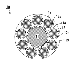
FIG. 1 shows an example of the reinforcing cord according to the
present invention. In FIG. 1, a cord 10 includes a carbon fiber strand 11
arranged in the central part, a plurality of glass fiber strands 12 arranged
around the carbon fiber strand 11, and an overcoating layer 13 (hatching is
omitted) formed to cover all the strands. A coating layer 11a is formed on
the surface of the carbon fiber strand 11 while coating layers 12a are formed
on the surfaces of the glass fiber strands 12. The coating layers lla and 12a
as well as the overcoating layer 13 may be omitted.
FIG. 2 schematically shows the arrangement of the carbon fiber
strand 11 and the glass fiber strands 12 that is obtained when the reinforcing
cord of the present invention is finally twisted. In this case, the plurality
of
glass fiber strands 12 are arranged spirally around the carbon fiber strand
11.
The number of the carbon fiber strand 11 and that of the glass fiber
strands 12 are determined according to the characteristics required for the
cord or the characteristics of the strands. Preferable examples of the ratio
of
[the number of carbon fiber strands] : [the number of glass fiber strands]
include 1 : 3 to 30, 2 : 6 to 30, and 3 : 10 to 40. When a plurality of carbon
fiber strands are to be arranged in the central part, they may be bundled and
then may be twisted or may be untwisted.
A carbon fiber strand often has lower adhesiveness to a matrix rubber
as compared to a glass fiber strand. Hence, it is preferable that the
plurality
of glass fiber strands be arranged to surround the carbon fiber strand so as
to
prevent the carbon fiber strand from being in contact with the matrix rubber.
The cord of the present invention can be manufactured by well-known
methods. An example of the method of manufacturing the cord according to
the present invention is described below.
Fiber strands may be formed by bundling fiber filaments. The
strand may be primarily twisted. A plurality of strands may be bundled and
6
CA 02519393 2005-09-16
twisted to form one strand. The strand thus formed may be subjected to a
specific treatment, for instance, a treatment using a RFL treatment solution.
When a coating layer is formed using the RFL treatment solution, the
strand may be immersed in the RFL treatment solution and then may be
heat-treated. The type of the rubber latex that is used in the RFL treatment
solution is not particularly limited. Examples of the rubber latex that can be
used herein include an acrylic rubber latex, an urethane rubber latex, a
styrene-butadiene rubber latex, a nitrile rubber latex, a chlorosulfonated
polyethylene latex, modified lances thereof, and mixtures thereof. The
coating layer may be formed using a common adhesive such as, for instance,
an epoxy compound or an isocyanate compound.
The carbon fiber strand and the glass fiber strands can be bundled by
a well-known method. For instance, they can be bundled using a guide
having a center guide hole and a plurality of peripheral guide holes arranged
around the center guide hole. The plurality of peripheral guide holes are
arranged at equal intervals around the center of the center guide hole.
One carbon fiber strand or a plurality of carbon fiber strands are put
into the center guide hole. The carbon fiber strands) may have been
primarily twisted or untwisted. The glass fiber strands are put into the
peripheral guide holes. Preferably, the glass fiber strand has been primarily
twisted. These strands are finally twisted to be bundled. The twist number
employed in the final twist is preferably about 0.5 to 10 times/25 mm. The
direction of the final twist may be the same as or opposite to that of the
primary twist of the glass fiber strands. When the final twist and the
primary twist are carried out in the same direction, i.e. to result in a so-
called
Lang lay, a cord with higher bending fatigue resistance can be obtained.
The apparatus to be used for manufacturing the cord of the present
invention is not specified. Various apparatuses can be used including a ring
twister, a flyer twisting frame, a strander, etc.
When the above-mentioned treatment agent alone does not allow the
reinforcing cord to have sufficiently high adhesiveness to the matrix rubber,
another adhesive further may be applied to the surface of the cord or a rubber
coating layer (an overcoating layer) may be formed on the surface of the cord.
The rubber coating layer can improve the affinity between the cord and the
matrix rubber. Rubbers that can be used for the rubber coating layer
includes hydrogenated nitrile rubber, chlorosulfonated polyethylene rubber
(CSM), chloroprene rubber, natural rubber, urethane rubber, etc. These
7
CA 02519393 2005-09-16
rubbers can be used together with a crosslinking agent. Generally, the
rubber to be used for the rubber coating layer is selected from well-known
rubbers according to the type of the matrix rubber. The weight of the rubber
coating layer is not particularly limited but is preferably 2.0 wt.% to 10.0
wt.% with respect to the weight of the cord with no rubber coating layer
having been formed thereon.
The cord of the present invention can be used for reinforcing various
rubber products and rubber members. The cord of the present invention is
particularly suitable for reinforcing rubber crawlers or rubber belts such as
toothed belts or moving belts. The reinforcing cord of the present invention
may be used in the form of one rope or in the form of a sheet-like reinforcer.
The sheet-like reinforcer can be obtained by loosely bonding a plurality of
the
cords arranged in parallel with each other.
Rubber Products
The rubber product of the present invention includes a rubber part
and a reinforcing cord embedded in the rubber part, wherein the reinforcing
cord is the above-mentioned reinforcing cord of the present invention. The
present invention is applicable to various rubber products and rubber
members, for example, rubber belts such as toothed belts and moving belts,
rubber crawlers, tire cords, etc.
In the rubber product of the present invention, it is preferable that
the ratio of the reinforcing cord of the present invention to the whole be in
the
range of 10 wt.% to 70 wt.%. The quantity and arrangement of the
reinforcing cord of the present invention are determined according to the
characteristics required for the rubber product.
An example of the rubber product of the present invention is
described below. FIG. 3 shows an exploded perspective view of a toothed belt
30. The toothed belt 30 includes a body 31 and a plurality of cords 32
embedded in the body 31. The body 31 is formed of rubber or rubber and
another material. The cords 32 are reinforcing cords according to the
present invention and are arranged in parallel with each other in the
direction in which the toothed belt 30 moves. A well-known member can be
used for the part other than the cords 32.
EXAMPLES
The present invention is described below further in detail using
examples.
Example 1
8
CA 02519393 2005-09-16
A carbon fiber strand was impregnated with a RFL treatment
solution and then was heat-treated (at 180°C for 120 seconds) to be
dried. A
carbon fiber strand provided with a coating layer thus formed (the coating
layer : 20 wt.%) was produced. The carbon fiber strand used herein was a
carbon fiber strand (having 400 tex, an outer diameter of about 0.76 mm, an
elastic modulus of 235 GPa, and a density of about 1.76 g/cm3~ an untwisted
product, manufactured by Toho Tenax Co., Ltd.) formed of a bundle of 6000
carbon fiber filaments (with a diameter of 7.0 Vim). The RFL treatment
solution used herein was a mixture obtained by mixing a solution of a
resorcinol formalin condensate (with a solid content of 8 wt.%), a
vinylpyridine-styrene-butadiene latex (with a solid content of 40 wt.%), and
a chlorosulfonated polyethylene rubber dispersion (with a solid content of 40
wt.%) at a solid-content weight ratio of 2 : 13 : 6.
In addition, glass fiber strands (having about 100 tex, an outer
diameter of about 0.35 mm, an elastic modulus of 70 GPa, a density of about
2.5 g/cm3, and a coating layer of 20 wt.%) were prepared that were provided
with a coating layer formed thereon. The glass fiber strands were produced
as follows. That is, after a strand formed by bundling 600 glass fiber
filaments (with an E-glass composition and a diameter of 9 ~.m) was
impregnated with the RFL treatment solution and then was heat-treated
(dried at 180°C for 120 seconds) to be dried, the strand was primarily
twisted
(2.0 times/25 mm) in the Sdirection.
Next, as shown in FIG. 1, nine glass fiber strands were arranged
around ane carbon fiber strand, which then was finally twisted (2.0 times/25
mm) in the Zdirection. Thus, a first cord (with a diameter of about 1.15
mm) was obtained. In the first cord, the ratio of the cross section of the
carbon fiber strand was 34% of the total of the cross section of the carbon
fiber strand and the total cross section of the glass fiber strands.
Furthermore, the linear density of the first cord was 1650 tex, i.e. its
weight
per length 1000 m was 1650 g.
A treatment agent for overcoating with the composition indicated in
Table 1 was applied to the first cord and then was dried. As a result, a
second cord with an overcoating layer thus formed was obtained. The
weight of the overcoating layer was 5 wt.% of the first cord.
9
CA 02519393 2005-09-16
Table 1
Components Ratio
(Weight Parts)
Chlorosulfonated Polyethylene Rubber (CSM)
(manufactured by Toso Co., Ltd., Product Name 5.25
TS-340~ a
chlorine content is 43 wt.%, and a sulfur content
is 1.1 wt.f)
P-dinitrosobenzene 2.25
Carbon Black 3.0
Mixed Solvent of Xylene and Trichloroethylene
85.0
(the weight ratio between xylene and trichloroethylene
= 1.5 : 1.0)
The second cord was subjected to measurements of tensile strength
per cord and elongation (%) at break. Furthermore, the tensile load applied
per cord was measured when the elongation in length of the cord reached
0.4% through application of a tensile load to the cord. A greater tensile load
applied at the time of the elongation indicates better dimensional stability.
The initial tensile strength was 710 N/cord. The elongation at break was
2.7%. The tensile load was 110 Nlcord.
In addition, one second cord was interposed between two rubber
sheets (with a width of 10 mm, a length of 300 mm, and a thickness of 1 mm),
which then was subjected to press vulcanization from its both sides at
150°C
for 20 minutes. Thus, a belt-like sample was produced. The rubber sheets
were formed of a blend of the components indicated in Table 2.
Table 2
Components Ratio
(Wei ht Parts)
Hydrogenated Acrylonitrile-Butadiene Rubber 100
(Zet of 2020, manufactured b JAPAN ZEON Cor
oration)
Zinc Oxide, Grade 1 5
Stearic Acid 1.0
HAF Carbon 60
Trioctyl Trimellitate 10
4,4-(a,a-Dimeth lbenz I)-di hen famine 1.5
2-Merca tobenzimidazole Zinc Salt 1.5
Sulfur 0.5
Tetrameth lthiuramsulfide 1.5
Cyclohexyl-Benzothiazylsulfenamide ~ 1.0
Next, the sample thus obtained was subjected to a bending test using
a bending tester 40 shown in FIG. 4. The bending tester 40 includes a flat
pulley 41 with a diameter of 25 mm, a motor (not shown in FIG. 4), and four
CA 02519393 2005-09-16
guide pulleys 42. First, the sample 43 produced in the above was hung on
the five pulleys. A weight was attached to one end 43a of the sample 43 to
apply an initial tensile force of 9.8 N to the sample 43. In that state, the
other end 43b of the sample 43 was made to reciprocate 10000 times at a
moving distance of 10 cm in the directions indicated with the double-headed
arrow, and thereby the sample 43 was bent repeatedly around the flat pulley
41. The bending test was carried out at room temperature. Thus, the
sample 43 was subjected to the bending test and then the tensile strength of
the sample was measured after the bending test. The tensile strength
retention (%) of the sample obtained after the bending test was determined,
with the tensile strength of the sample obtained before the bending test being
taken as 100%. A higher value of the tensile strength retention indicates
higher bending fatigue resistance. The tensile strength retention of the
sample according to Example 1 was 83%.
Example 2
First, a carbon fiber strand with a coating layer was produced and
then was primarily twisted (2.0 times/25 mm) in the Sdirection as in
Example 1. The carbon fiber strand thus obtained was used for a first cord
(with a diameter of 1.18 mm). Except for that, the first cord was produced
by the same method as in Example 1. The linear density of the first cord
was 1770 tex, i.e. its weight per length 1000 m was 1770 g.
Next, an overcoating layer was formed on the surface of the first cord
as in Example 1. Thus, a second cord with the overcoating layer was
obtained. The weight of the overcoating layer was 5 wt.% of the first cord.
This second cord was evaluated as in Example 1. Furthermore, a sample to
be used for the bending test was produced and then was subjected to the
bending test as in Example 1.
As a result, the initial tensile strength per cord was 1080 Nlcord.
The elongation at break was 2.1%. The tensile load applied per cord when
the elongation was 0.4% was 200 Nlcord. Furthermore, the tensile strength
retention obtained after the bending test was 71%.
Comparative Example 1
In Comparative Example 1, a cord was produced using no carbon
fiber strand. Specifically, the glass fiber strands used in Example 1, i.e.
glass fiber strands that had been subjected to the RFL treatment and then
had been primarily twisted in the Sdirection, were prepared first. Then, 11
glass fiber strands thus prepared were bundled and then were finally twisted
11
CA 02519393 2005-09-16
(2.0 timesl25 mm) in the Zdirection. Thus, a first cord (with a diameter of
about 1.13 mm) including no carbon fiber was obtained. The linear density
of the first cord was 1440 tex, i.e. its weight per length 1000 m was 1440 g.
Next, an overcoating layer was formed on the surface of the first cord
as in Example 1. Thus, a second cord with the overcoating layer was
obtained. The weight of the overcoating layer was 5 wt.% of the cord. This
second cord was evaluated as in Example 1. Furthermore, a sample to be
used for the bending test was produced and then was subjected to the
bending test as in Example 1.
As a result, the initial tensile strength per cord was 890 N/cord. The
elongation at break was 3.4%. The tensile load applied per cord when the
elongation was 0.4% was 80 N/cord. Furthermore, the tensile strength
retention obtained after the bending test was 51%.
Comparative Example 2
In Comparative Example 2, a cord was produced using no glass fiber
strands. Specifically, first, carbon fiber strands (having 800 tex, an elastic
modulus of 240 GPa, and a density of about 1.80 g/cm3~ an untwisted product,
manufactured by Toho Tenax Co., Ltd.) formed of a bundle of 12000 carbon
fiber filaments (with a diameter of 6.9 Vim) were twisted (2.0 timesl25 mm).
Thereafter, a treatment agent for overcoating was applied thereto arid then
was dried. Thus, a cord (with a diameter of 1.10 mm) with an overcoating
layer was obtained. The linear density of this cord was 1140 tex, i.e. its
weight per length 1000 m was 1140 g. The weight of the overcoating layer
was 5 wt.% of the cord. This cord was evaluated as in Example 1.
Furthermore, a sample to be used for the bending test was produced and then
was subjected to the bending test as in Example 1.
As a result, the initial tensile strength per cord was 1440 N/cord.
The elongation at break was 2.1%. The tensile load applied per cord when
the elongation was 0.4% was 90 N/cord. Furthermore, the tensile strength
retention obtained after the bending test was 68%.
Table 3 indicates the type of the strands, the linear density, the
tensile load applied when the elongation was 0.4%, and the tensile strength
retention with respect to Examples 1 and 2 as well as Comparative Examples
1 and 2.
12
CA 02519393 2005-09-16
Table 3
Constituent Tensile
Fibers
of
Tensile Strength
Strand Linear Load at
(the the
Number
of
Retention
Strands) Density Time of after
Ben~ng Test
[gI1000 Elongation
m]
Center Periphery [Nlcord]
Example Carbon E-Glass 1650 110 83
1
Fiber Fiber
(1) (9)
Example Carbon E-Glass 1770 200 71
2
Fiber Fiber
(1) (9)
ComparativeE-Glass
_ 1440 80 51
Example Fiber
1 (11)
ComparativeCarbon
_ 1140 90 68
Exam 1e Fiber
2 (2)
As is clear from Table 3, in the case of the cords of Examples 1 and 2,
the tensile load applied when the elongation was 0.4% was greater and the
tensile strength retention was higher. Accordingly, the cords of Examples 1
and 2 were excellent in dimensional stability and bending fatigue resistance.
On the other hand, in the case of the cord of Comparative Example 1 in which
the glass fiber strands alone were used as reinforcing fibers, both the
tensile
load applied at the time of elongation and the tensile strength retention were
lower. Hence, the cord of Comparative Example 1 was inferior to the cords
of Examples 1 and 2 in terms of both the dimensional stability and the
bending fatigue resistance. Furthermore, the cord of Comparative Example
2 in which carbon fiber strands alone were used as reinforcing fibers was
superior to the cord of Comparative Example 1 but was inferior to the cords of
Examples 1 and 2 in terms of the tensile load at the time of elongation and
the tensile strength retention.
The cord of Example 1 had a higher tensile strength retention after
the bending test and a less tensile load at the time of elongation as compared
to the cord of Example 2. Hence, the cord of Example 1 is superior in
bending fatigue resistance to the cord of Example 2. On the other hand, the
cord of Example 2 is superior in dimensional stability to the cord of Example
1.
Generally, in the case of a twisted cord, the bending fatigue resistance
improves with an increase in twist number while the dimensional stability
improves with a decrease in twist number. In the case of the cord of
Example 1, when it is finally twisted in the Zdirection, the carbon fiber
strand (that has not been primarily twisted) also is twisted. As a result, the
13
CA 02519393 2005-09-16
carbon fiber strand is twisted in the Zdirection at about 2.0 times/25 mm.
On the other hand, in the case of the cord of Example 2, when it is finally
twisted in the Zdirection, the degree of the primary twist of the carbon fiber
strand (that has been primarily twisted in the Sdirection) decreases and
thereby the primary twist mostly is cancelled. Conceivably, the difference in
degree of such twists may cause the difference in performance between the
cord of Example 1 and the cord of Example 2. Accordingly, it is preferable
that after the final twist, the carbon fiber strand have a substantial twist
number in the range of 0.5 to 5.0 times/25 mm when the bending fatigue
resistance is considered as important and have a substantial twist number of
less than 0.5 time/25 mm (including the case where the carbon fiber strand is
untwisted) when the dimensional stability is considered as important.
The present invention is applicable to other embodiments as long as
they do not depart from the intention and essential characteristics thereof.
The embodiments disclosed in this specification are to be considered in all
respects as illustrative and not limiting. The scope of the present invention
is indicated by the appended claims rather than by the foregoing description,
and all changes which come within the meaning and range of equivalency of
the claims are intended to be embraced therein.
INDUSTRIAL APPLICABILITY
According to the present invention, a reinforcing cord can be obtained
that has sufficient tensile strength for reinforcing rubber products as well
as
high dimensional stability and bending fatigue resistance. The cord is
applicable to various rubber products. Particularly, the cord is used suitably
for rubber products that are required to have high dimensional stability and
high bending fatigue resistance. For instance, the cord is used suitably for
toothed belts such as timing belts, and rubber crawlers.
14