Note: Descriptions are shown in the official language in which they were submitted.
CA 02519423 2005-09-16
WO 2004/082740 PCT/US2004/009392
ELECTRICAL CONNECTOR APPARATUS,
SYSTEM AND METHOD FOR USE WITH MEDICAL DEVICES
Field of the Invention
The present invention relates to an electrical connector apparatus, system
and method for use with medical devices. The present invention is especially
suited
for use with medical devices useful in detecting the occurrence of
extravasation
during a fluid inj ection procedure or IV administration.
Background of the Invention
Extxavasation is the escape, discharge, pouring out or euuption of a fluid
from its intended channel or vessel into the individual's surrounding tissue.
Ea~travasation rnay occur, for example, with the use of an IV catheter.
Extravasation may also occur during contrast fluid media injection procedures
using power injectors. In those cases, contrast is inadvertently injected into
the
tissue surrounding the blood vessel, instead of into the blood vessel itself.
Although not life-tlu-eatening, extravasation causes discomfort to the
individual
and requires that the procedure be terminated and reinstituted. Complications
related to extravasation may be quite severe and may include tissue necrosis.
This
may require reconstructive surgery to repair.
There exist devices which may be used to detect extravasation in an
individual. A device useful for detecting extravasation is currently
commercially
available under the name "Extravasation Detection Patch" or "EDA Patch" (E-Z-
EM, Inc., Lal~e Success, New Yorlc). This device is described in U.S. Patent
No.
5,964,703 to Goodman et al. Similarly, a method for detecting extravasation
using
an electrode patch is disclosed in U.S. Patent No. 5,947,910 to Zimmet. Both
of
these patents are incorporated herein by reference in their entirety.
CA 02519423 2005-09-16
WO 2004/082740 PCT/US2004/009392
In one alternative embodiment, an extravasation detection patch is applied
to the slcin of an individual, contains electrical conductors coated with a
hydrogel
layer configured to measure skin impedance. A single interconnect cable
connects
the electrical conductors on the patch to a microprocessor, wherein the
microprocessor processes signals from the patch, sets off an alarm if
extravasation
is detected, and stops a power injector to which it connnunicates with. The
microprocessor may also have a user interface.
Currently, extravasation detection devices such as the EDA patch are
affixed to an individual after the catheter for transmitting fluid to the
individual has
been positioned, for example. Thus, attaclnnent usually takes place in the
room
where the injection procedure is to take place, such as the CT scanning room.
~nce affixed to the individual, the extravasation detection device is
connected via
a single electrical interconnect cable to a microprocessor. The cable
simultaneously transmits electricity to the electrodes of the patch and also
transmits electrical signals emitted from the electrodes to the
microprocessor,
which interprets the signals transmitted fT~ln the electrodes of the patch.
In practice connecting the e~~travasation detection device to a single
interconnect cable can be very awkward because the individual is generally
lying
down on the scanner gantry and the individual's ann is in a bent position
during
connection. Additionally9 the cable rnay be very long due to the physical
characteristics of the room and therefore difficult to handle. This
awkwardness
malLes the connection process very time consuming and can lead to service back
up. Additionally, the connection on the extravasation device can be obstructed
and
difficult to access, due to an existing IV catheter, dressings, tape, etc.,
thereby
5 increasing the likelihood of a compromised electrical connection. This could
lead
to problems in using the extravasation device.
Further, if the individual is undergoing more than one procedure for which
extravasation detection is required, such as a CT scanning procedure followed
by
an IV administration, these procedures will generally be conducted in separate
rooms. Thus, using current techniques, the individual must be fitted with
multiple
extravasation devices and/or the extravasation device must be connected to the
microprocessor via the single interconnect cable multiple times.
2
CA 02519423 2005-09-16
WO 2004/082740 PCT/US2004/009392
Summary of the Invention
Accordingly, the present invention seeks to remedy the problems of the
prior art by providing a convenient, efficient and effective means for
electrically
coimecting a medical device affixed to an individual, such as a device for
detecting
extravasation, to an electrical circuit. The circuit may contain analog and
digital
components, for example, wherein the digital components are useful in
interpreting
feedback from the medical device. Preferably, the electrical circuit includes
a
microprocessor.
It is therefore an obj ect of the present invention to provide an electrical
connector apparatus suitable for use with a medical device, the apparatus
having a
first component including a first electrical connector adapted to electrically
mate
with a medical device, the first electrical connector having a means for
preventing
decoupling of said first electrical connector and said medical device, and a
second
electrical connector; and a second component comprising an electrical cable
having a proximal and a distal end, a third electuical connector located on
said
distal end of said cable for establishing a connection with an electrical
circuit and a
fourth electrical connector located on said proxunal end of said cable;
wherein said
second electrical connector is mated with said fourth electrical connector.
In one aspect of the invention, the electrical connector apparatus provided
is suitable for use with an extravasation detection device9 wherein the
extra~rasation
detection device comprises electrical conductors (electrodes). Such an
apparatus
comprising a first component including a first electrical connector adapted to
receive electrical signals from the one or more electrodes of the
extravasation
detection device, the first electrical coimector having a means for preventing
decoupling of said first electrical connector and said one or more electrodes,
a
second electrical connector, and an electrical cable positioned between said
first
and said second electrical connectors; and a second component including an
electrical cable having a proximal and a distal end, a third electrical
connector
located on said distal end of said cable for establishing an electrical
connection
with an electrical circuit adapted to xeceive electrical signals from said one
or more
electrodes, wherein said electrical circuit includes a microprocessor, and a
fourth
electrical connector located on said proximal end of said cable; said second
CA 02519423 2005-09-16
WO 2004/082740 PCT/US2004/009392
electrical connector and said fourth electrical connector being an
interfitting female
type cable connector and male type cable connector, respectively, such that
when
said second electrical connector and said fourth electrical connector are
coupled an
electrical connection is established.
It is also an object of the present invention to provide an electrical
connection system suitable for use with a medical device. In one aspect of the
invention, the medical device is used to detect extravasation in an individual
undergoing a medical procedure by measuring tissue impedance during the
injection procedure.
It is an additional object of the present invention to provide a method for
electrically connecting a medical device to an electrical circuit, wherein the
medical device is affixed to an individual. In one aspect of the present
invention,
the method comprises the steps of (i) affixing a medical device for detecting
extravasation to an individual undergoing a fluid injection procedure, wherein
said
medical device includes one or more electrodes; attaching to said medical
device a
first component including a first electrical connector adapted to receive
electrical
signals from said one or mare electrodes9 the first electrical connectcar
having a
means for preventing decoupling of said first electrical connector and said
one or
more electrodes, and a second electrical connector; (ii) attaching to an
electrical
~0 circuit a second component including aai electrical cable having a proximal
and a
distal end9 a third electrical connector located on the distal end of said
cable for
establishing an electrical connection with said electrical circuit, wherein
said
electrical circuit is adapted to receive signals from said one or more
electrodes, and
a fourth electrical comlector located on said proximal end of said cable; and,
(iii)
mating said second electrical connector with said fourth electrical connector,
said
second electrical comlector and said fourth electrical connector being an
interfitting female type cable connector and male type cable connector,
respectively, such that when said second electrical connector and said fourth
electrical connector are coupled an electrical connection is established.
Brief Description of Drawings
Figure 1 is a perspective view of an alternative embodiment of the device
of the present invention.
4
CA 02519423 2005-09-16
WO 2004/082740 PCT/US2004/009392
Figure 2 shows a perspective view of a component of the present
invention.
Figure 3 shows a frontal view of an alternative electrical connector of the
present invention.
Figure 4A shows a completed assembly of an alternative embodiment of
the present invention.
Figure 4B shows an assembly of an alternative embodiment of the present
invention.
Figure 5 shows an alternative method of the present invention.
Figure 6 shows an alternative embodiment of the present invention.
Corresponding reference characters indicate corresponding parts
throughout the several views of drawings.
Detailed Descr iption of the Invention
The present invention relates to an electrical connector apparatus system
and method suitable for use with a medical device. The present invention is
especially suited for use v~ith medical devices for detecting extravasation
during a
medical procedure such as a fluid injection procedure. Currently, there exist
devices for detecting extravasation, wherein the device is temporarily affixed
to an
individual undergoing a fluid injection procedure, the device having
electrodes
'?0 which generate electrical signals indicative of tissue impedance. Changes
in tissue
impedance indicate the occurrence of extravasation. The electrodes are
connected
via an electrical cable to an electrical circuit adapted to receive and
interpret the
electrical signals indicative of tissue impedance.
Prior art electrical connectors used to connect a device for detecting
extravasation to an electrical circuithnicroprocessor include devices affixed
to an
individual's slcin near which are capable of transmitting electrical signals
to and
from the electrical circuit, wherein the electrical signals represent tissue
impedance
measurements. The prior art is a long, single intercomlect cable. Problems
associated with the prior art include difficulty in attaching the single
interconnect
cable to the extravasation device due to the cable's length, the individual's
position,
e.g., reclining, and obstructions near the device such as medical tape, such
that the
5
CA 02519423 2005-09-16
WO 2004/082740 PCT/US2004/009392
electrical connection between the extravasation device and prior art
electrical
connector is compromised. Further, due to its length, the prior art is often
difficult
and awkward to attach, thereby resulting in increased individual waiting time
and/or procedure time, because the extravasation detection device is generally
connected to the electrical circuit in the room where the medical procedure is
to
take place. Also, if the individual is undergoing multiple procedures which
require
extravasation detection, once the extravasation device is connected to the
single
interconnect, then the individual is essentially rendered immobile, due to
length
and weight of the singe cable, which may drag alone behind the individual,
such
that the individual or people may trip on it, or it might tangle or knot.
Thus, with
prior art devices, a medical device on an individual must be connected and
disconnected to an electrical circuit in each procedure room.
The present invention overcomes these problems by providing an apparatus
such as the one shown in FIG. 1, which represents an alternative embodiment of
the present invention. Referring to FIG. 1, the electrical connector apparatus
of the
present invention comprises a first component (1). First component (1)
includes
electrical connector (3) adapted to establish an electrical connection with a
medical
device, such as a device for use in detecting extravasation. In certain
embodiments
herein, electrical connector (3) includes any suitable commercially available
low
?0 voltage connector including, but not limited to, those manufactured by
Alden,
LEIS~~ V~~ Fischer and others. In other embodiments herein, electuical
connector (3) is a male micro I~IN connector. In another embodiment,
electrical
connector (3) is adapted to establish an electrical connection with a medical
device
having a circular style connector adapted to accept pin contacts, for example.
In a preferred embodiment, electrical connector (3) is capable of
establishing a low profile planar electrical interface with electrode elements
useful
in detecting tissue impedance, wherein the electrodes are part of a medical
device
for detecting extravasation during a medical procedure. In this manner,
electrical
connector (3) represents an improvement over the prior art in several ways.
For
example, it permits the economical manufacture of the extravasation detecting
device via automated stack-up and die cutting of constituent materials
comprised
entirely of laminates, applied gels and applied adhesives. Also, it provides
for
6
CA 02519423 2005-09-16
WO 2004/082740 PCT/US2004/009392
optimal placement, routing and strain relief of the associated cable relative
to the
individual when in CT clinical setting.
In a preferred embodiment, electrical connector (3) includes a securing
means for engaging and disengaging both physical and electrical connection to
a
medical device, such as an extravasation device. Securing means suitable for
use
in the present invention include, but are not limited to, any connnercially
available
locking type mechanism suitable for use with an electrical connector, wherein
the
mechanism sufficiently prevents decoupling of the connector when mated. In an
alternative embodiment, electrical connector (3) is an Alden connector or any
other
similar type of electrical connector possessing threaded shells that are free
to rotate
relative to the electrical contacts, thereby facilitating a locking or
securing
connection to a threaded receptacle on the medical device or electrical
circuit. In
alternative embodiments, electrical connector (3) is any commercially
available
locking electrical connectors such as those manufactured by Alden possessing
spring loaded shells that partially rotate to create a bayonet style locking
interconnect v~ith a receptacle designed to accept the re-entrant or latch
geometry
of tile connector shell. Additionally, commercially available locking
electrical
connectors such as those manufactured by LEM~, W.~. Fischer and ~I~U which
provide spring loaded keys and flanges to lock the electrical connector with
the
?0 medical device or electrical circuit are suitable for use herein. Usually,
the
securing means can be easily and efficiently engaged and disengaged, such that
it
only requires manipulation by the thumb and index finger of one hand.
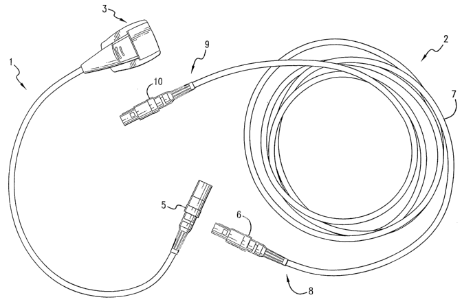
Component (1) also includes female cable connector (5) for electrically
coupling with male cable connector (6). Male cable connector (6) is located on
the
distal end (~) of cable (7). Cable (7) also has a proximal end (9). Electrical
connector (10) is positioned at the proximal end (9) of cable (7). In one
embodiment, electrical connector (10) is a male type electrical connector
adapted
for electrically connecting cable (7) to an electrical circuit. As used
herein,
electrical circuit includes, but is not limited to, a wall socket, power
strip, battery,
generator, microprocessor or any other similar device. In one embodiment, the
electrical circuit has both analog and digital components. In a preferred
embodiment, the electrical circuit includes a microprocessor. The digital
7
CA 02519423 2005-09-16
WO 2004/082740 PCT/US2004/009392
components being useful for providing feedback on the electrical signals
received
from the medical device. In other embodiments, cable connector (10) is
permanently coimected to an electrical circuit.
Cables suitable for use herein include one or more strands of insulated
electrical conductors laid together, usually around a central core and
surrounded by
insulation. W preferred embodiments herein, to assure flexibility and
longevity of
the cable, each conductor is comprised of several strands of copper wire
contained
in either a poly-vinyl chloride (PVC) or Teflon insulating jacket. The number
of
conductors used may depend upon the number of discreet signals needed; for
example, in the case of the EDA device, four are sufficient. These conductors
are
bundled together and surrounded by a conductive shield, which may be comprised
of a copper or aluminum foil. Alternatively, the shield could be comprised of
a
woven braid of fme wire. This shielding layer surrounding the bundle of
individual signal wires prevents any extraneous electromagnetic energy in the
clinical environment from interfering with their signal carrying capability.
To
keep the bundle of signal ~rires and their shielding layer in tact in a
singiblar
conduit, an outer jacket of PVC or Teflon is extruded over this assembly. Such
cables are routinely available from such wire manufacturers as WEIC~ and Alpha
Wire and Cable.
FIG. 2 is a top view of an embodiment of first component (1) of the present
invention. W FIG. 29 first component (1) has a proximal end (16) and a distal
end
(17). First component (1) includes electrical connector (3) located at
proximal end
(16).
W a preferred embodiment, component (1) is attached to the medical device
after the device has been placed on or near an individual, or affixed to the
individual. For example, component (1) would be attached after the catheter
insertion point is determined and an extravasation detection patch is affixed
to skin
of the patient near the injection site. Thus, component (1) may be attached to
a
medical device in a room or place other than where the medical procedure,
e.g.,
injection procedure or scanning procedure is to take place. (See FIG. 5) For
example, component (1) may be attached to an extravasation device affixed to
an
individual while the individual is in a hallway, waiting room or individual
8
CA 02519423 2005-09-16
WO 2004/082740 PCT/US2004/009392
preparation room. Further, once component (1) is attached to the medical
device,
the individual is mobile and may be moved to different procedure rooms without
detachment of component (1) from the medical device. Alternatively, component
(1) can be attached to a medical device before the device is affixed on or
near the
individual. Thus, component (1) represents an improvement over the prior art,
because it is short and compact, and therefore does not tangle, knot or drag
behind
the patient, and also does not weigh down the patch such that the patch is
dislodged from the skin of the individual.
In one embodiment herein, an individual is to be injected with a contrast
agent for a CT abdominal scan, and it is desired that the individual be
monitored
for extravasation during the injection procedure. In the prior art, the device
for
detecting extravasation would have to have been connected to an electrical
circuit/microprocessor in the CT scamzing room via a single cable. However, as
shown in FIG. 5, component (1) of the present invention may be attached to an
extravasation device in a hallway or waiting room, for example. Thus, when the
scanning room is free, the individual can be moved into the scarming room,
component (1) quickly connected to component (2), which is cormacted to an
electrical circuit, and the injection/scarming procedure may be performed.
Component (1) may then be decoupled from component (~), and the individual
may be moved t~ another r~om wlthout decoupling of component (1) from the
extravasation device. The present invention therefore decreases individual
waiting
time for a CT scan and increases the efficiency of expensive and limited
medical
scanning equipment. If a hospital so desires, it may further increase the
efficiency
of medical equipment such as CT scanning equipment by using multiple connector
components (1) on multiple individuals. In that case, if a hospital is
performing a
CT scan on multiple individuals, each individual may be fitted with a
component
(1) outside the scanning room, such that when they enter the scanning room
their
component (1) may be readily attached/detached to a single component (2.)
inside
the scanning room.
In reference to FIG. 2, component (1) may also comprise a length of cable
(14). Cable (14) may be of variable length. In one embodiment, the length of
cable is about 0.5 inches to about 60 inches, or about 2 to about 40 inches.
9
CA 02519423 2005-09-16
WO 2004/082740 PCT/US2004/009392
Preferably, the length of cable is about 20 to about 30 inches, and even more
preferably about 24 inches. It has been discovered that this length is optimal
for
effecting ease of connection of component (1) to a medical device without
compromising individual mobility.
Component (1) may also comprise a female type comlector (5) located at
the distal end (17) of component (1). hi one embodiment, female type connector
(5) is a female micro-din connector.
FIG. 3 shows a frontal view of female comlector (5). In FIG. 3, female
connector (5) includes five apertures (20-24) for receiving a male electrical
cable
IO connector. In an alternative embodiment, female comlector (5) has at least
one
aperture for receiving a male electrical medical cable connector.
FIGS. 4A and 4B show a preferred embodiment of electrical connector (3)
of the present invention. In reference to FIG. 4A, electrical connector (3)
consists
of an ultrasonically welded plastic connector enclosure (38) that encapsulates
a
retaining clip (40) for purposes of securing a medical device such as an
extravasation device to electrical connector (3). Retaining clip (40) may
rotationally open and close within a hinge point in c~arporated into the
design of the
connector enclosure (38). Retaining clip (40) closes via direct finger
pressure by
the user. When closed, the connecting tab of the extravasation device being of
laaninated constuucti~n, for example, is compressed betv~een the retaining
clip (40)
and electrical contacts (42). The exp~sed conductive elements ~f the
extravasation
device maintain secure planar electrical contact with the electrical contacts
(42)
belonging to the comlector (3) when the retaining clip (40) is closed.
Discomlection of the extravasation device from the connector (3) is done so by
actuating the releasing button (44) with finger pressure which in turn
releases the
retaining clip (40) from the closed position. Affixed to the bottom of the
comlector
enclosure, as shown in FIG. 4B, is a self interlocking material (46) such as
VELCRO of 3M Dual-Lock material. Interlocking material (46) is used for
convenient attachment and detachment of the electrical connector (3) to a
securing
belt of like material affixed round the peripheral limb of the individual
adjacent to
an extravasation device also affixed to the individual. Affixing connector (3)
to the
surface of an individual peripheral limb through the user of an interlocl~ing
CA 02519423 2005-09-16
WO 2004/082740 PCT/US2004/009392
material (46) supports optimal function between the connector (3) and
extravasation device by providing a strain relief between them.
The device of the present invention is suitable for use with an E-Z-EM
EDA patch. The EDA patch comprises a layer of hydrogel containing electrodes.
Once the EDA patch is affixed to the skin of the individual, an alternating
electrical current is applied to a pair of outer electrodes, thereby inducing
an
electrical current between a pair of inner electrodes. This current is a
function of
the tissue impedance. Tissue impedance is measured during the injection
procedure
using the electrical information sensed by the inner pair of electrodes. This
electrical information is outputed in the form of a signal received by an
electrical
circuit/microprocessor containing both analog and digital components. The
tissue
impedance is monitored throughout the injection procedure by the electrical
circuit
and changes in the tissue impedance indicate extravasation.
In an alternative embodiment, the device of the present invention comprises
one or more electrical cables positioned in line between the first component
and
the second component of the invention. Such a device may be desirable, for
e~~ample, if the individual is to be located far away from the electricity
supply
source, or to acconunodate room geometry. Referring to FIG. 6, component (1)
and component (2) of the present invention are shown. In one embodiment, the
device of the present invention includes component (26), having an electrical
cable
(27) having a proximal end (30) and distal end (31). In one embodiment,
electrical
connector (28), located at proximal end (30), is suitable for mating with
electrical
conductor (5). In one embodiment, electrical comzector (28) is a male type
cable
connector or similar device. Electrical connector (29), located at distal end
(31), is
suitable for mating with electrical connector (6). In one embodiment,
electrical
connector (29) is a female type electrical connector or similar device.
SYSTEM
The present invention also provides an electrical connection system suitable
for use with a medical device, wherein the device is useful in detecting
extravasation in an individual undergoing a medical procedure. The medical
procedure may include, but is not limited to, any fluid injection procedure
such as
injection via a power injector, IV or infusion pump. For example, the system
of the
11
CA 02519423 2005-09-16
WO 2004/082740 PCT/US2004/009392
present invention may be used in conjunction with an individual undergoing
vascular fluid injection procedure, intravenous (IV) administration of fluid
to an
individual, or a CT scanning procedure wherein the individual is inj ected
with a
contrast agent.
In a preferred embodiment, the system of the present invention includes a
medical device useful in detecting extravasation in an individual undergoing a
medical procedure, the medical device having one or more electrodes; a first
component including a first electrical connector adapted to electrically
couple with
the medical device, and a second electrical connector; a second component
including an electrical cable having a proximal and a distal end, a third
electrical
connector located on said distal end of said cable for establishing an
electrical
connection with an electrical circuit and a fourth electrical connector
located on
said proximal end of said cable; and an electrical circuit; wherein said
second
electrical connector is adapted to electrically couple with said fourth
electrical
connector. Further, in the system of the present invention, the first
component may
include an electrical cable positioned between said first and said second
electrical
connector s.
As previously noted, the electrical circuit of the present invention may
include analog and digital circuit components for interpreting the electrical
signals
reCel~led from the medical device. Preferably, the electrical circuit includes
a
microprocessor. In an alternative embodiment, the system of the present
invention
has one or more electrical cables positioned in line between the first
component
and the second component of the invention. Such a system anay be desirable,
for
example, if the individual is to be located far away from the electricity
supply
source.
In the system of the present invention, the second and fourth electrical
connectors are preferably interfitting male and female type cable connectors.
Further, the first electrical connector of the present system may include any
suitable commercially available low voltage connector.
12
CA 02519423 2005-09-16
WO 2004/082740 PCT/US2004/009392
METHOD
The present invention is also directed to a method for electrically
connecting a device useful in detecting extravasation in an individual
undergoing a
medical procedure such as a fluid injection procedure. In a preferred
embodiment,
the method of the present invention comprises the steps of (1) affixing a
medical
device for detecting extravasation to an individual undergoing a medical
procedure, wherein said medical device includes one or more electrodes; (2)
coupling said one or more electrodes with a first electrical connector of a
first
component, said first electrical connector adapted to receive electrical
signals from
said one or more electrodes, and said first electrical having a securing means
for
preventing decoupling of said first electrical connector and said one or more
electrodes, and a second electrical coimector; (3) coupling a microprocessor
with a
third electrical connector of a second component, said second component
including
an electrical cable having a proximal and a distal end, said third electrical
connector located on said distal end of said cable for establishing an
electrical
connection v~ith said microprocessor9 avherein said microprocessor is adapted
to
receive signals from said one or more electrodes9 and a fourth electrical
connector
located on said proximal end of said cable; (4) mating said second electrical
connector with said fourth electrical connector, said second electrical
connector
?0 and said fourth electrical connector being an interfitting female type
cable
connector and male type cable cormector, respectively, such that when said
second
electrical connector and said fourth electrical connector are mated an
electrical
comzection is established.
In certain embodiments herein, the method of the present invention
comprises simultaneously connecting a second individual to a medical device
using a second first component while the first individual is comlected to the
microprocessor component during the procedure. In a preferred embodiment, the
method of the present invention comprises the steps of (1) comiecting at least
a
first and a second medical device to a first and a second individual,
respectively,
wherein the at least first and second medical devices are useful in detecting
extravasation; (2) connecting the at least first medical device to a first
component
(1) of the present invention; (3) connecting the at least second medical
device to a
13
CA 02519423 2005-09-16
WO 2004/082740 PCT/US2004/009392
second first component (1) of the present invention; (4) connecting the first
component (1) to a component (2) of the present invention; (5) performing a CT
scan on the first individual; (6) decoupling said first component (1) from the
first
component (2); (7) connecting the second component (1) to the component (2) of
step 4; performing a CT scan on the second individual; and decoupling the
second
component (1) from the component (2).
Although particular embodiments of this invention have been described and
illustrated herein, the present invention can be further modified within the
scope
and spirit of this disclosure. This application is therefore intended to cover
any
variations, uses, or adaptations of the invention using its general
principles.
Further, this application is intended to cover such departures from the
present
disclosure as come within known or customary practice in the art to which this
invention pertains and which fall within the limits of the appended claims.
Further,
the present invention may comprise, consist of or consist essentially of the
components or steps disclosed in this specification.
14