Note: Descriptions are shown in the official language in which they were submitted.
CA 02519530 2011-05-05
I
WRITING INSTRUMENT WITH CUSHIONING ELEMENT
Field Of The Invention
[002] The present invention relates to a writing instrument with a cushioning
element. More particularly, the present invention relates to a cushioning
element at
the back, non-writing end of a writing instrument which allows the writing tip
of the
writing instrument to react to force applied to the tip of the writing
instrument during
writing, thereby providing a certain feeling to the user while writing.
Background Of The Invention
[003] In general, writing instruments such as pens have a main body into
which a cartridge with a writing tip is held in place such that a user may
write with the
writing instrument. For most writing instruments, the writing tip is held in
substantially rigid relation to the rest of the instrument during writing.
However, in
some cases a cushioning element, such as a spring or other biasing element,
holds the
cartridge and thus the writing tip in the writing instrument in a non-rigid
manner. The
cushioning element allows the writing tip to be biased into the main body of
the
instrument when force is applied to the writing tip during writing. This
provides a
certain feel to the user during writing that many find desirable.
[004] The use of cushioning elements has been well known in the prior art.
For instance, spring elements have been used to provide cushioning to the
writing tip.
Other elements, such as foam inserts, can also be found in the prior art.
However, all
of the cushioning elements in the prior art are elements separate from the
rest of the
writing instrument. Thus, the separately formed cushioning element must be
attached
or coupled to the other parts of the writing instrument, increasing the
complexity of
manufacturing and/or assembling of the writing instrument. Also, the addition
of
another element to the writing instrument increases the likelihood of some
failure in
the attachment of the elements of the writing instrument to each other,
reducing the
overall reliability of the writing instrument.
CA 02519530 2005-09-12
WO 2004/082963 PCT/US2004/007744
2
[005] Thus, there remains a need for a writing instrument with a cushioning
element for the writing tip that is formed for ready assembly with the writing
instrument and that is easy to manufacture.
[006] In addition, resilient elements may be prone to wear or to reduced
efficacy upon repeated usage or upon overuse or abuse. For instance, a
cushioning
element for writing tip of a writing instrument may lose its resiliency after
repeated
use over over-compression. If used in excess, or abused, the cushioning
element can
flatten out or take a set or otherwise lose efficacy. It therefore would be
desirable to
reduce such risk of loss of efficacy of a cushioning element.
Summary Of The Invention
[007] One aspect of the present invention provides a writing instrument with a
cushioning device formed integral with another element of the writing
instrument.
The writing instrument has a barrel, a cartridge with a writing tip, and an
end plug. A
cushioning element in one embodiment is formed integrally with a part of the
instrument, such as the end plug. In an exemplary embodiment, the cushioning
element is a spring element. The cartridge may be held in place in the barrel
of the
writing instrument via the cushioning element, which is coupled to the
proximal end
of the barrel. The cushioning element biases the writing tip in an axial
direction out
of the barrel and allows the writing tip to be axially displaceable into the
body of the
writing instrument when force is applied to the writing tip during writing or
marking.
This promotes a certain feel to the user that is transmitted during writing.
Furthermore, the cushioning element preferably is configured to allow the end
plug to
be formed by an injection molding process.
[008] The present invention provides a writing instrument with a cushioning
element formed integral with another element of the writing instrument. This
is
distinguished from the prior art, which required subsequent assembly or
attachment of
a cushioning element with another element of a writing instrument after both
elements
had been fully formed. In the writing instrument of the present invention, the
cushioning element and the element to which it is formed integral with are
inseparable
and act as one element once the formation process of the elements is complete,
requiring no further assembly or attachment to each other before use in the
writing
instrument.
CA 02519530 2005-09-12
WO 2004/082963 PCT/US2004/007744
3
[009] According to another aspect of the present invention, that may be
independent of the above-described aspect of the present invention or may be
applied
in combination with the above-described aspect of the present invention, the
cushioning element may be formed to have varying spring rates. It will be
appreciated that if the cushioning element is in the form of a coil spring, a
variable
spring rate may be provided by forming the coil spring itself to have a
variable spring
rate. For instance, the distance between the coils of the coil spring may vary
so that
coils bottom out successively. Each time a coil bottoms out, the spring rate
of the
spring increases.
[010] In accordance with yet another aspect of the present invention that may
be applied with any or all of the above-described aspects of the present
invention, a
stop element may be provided to limit the compression of the cushioning
element.
For example, if the cushioning element is in the form of a coil spring, the
stop element
may be in the form of a stop pin extending axially within and through the coil
spring.
The stop pin is shorter than the length of the coil spring such that the coil
spring may
compress freely without being impeded by the stop pin up to a predetermined
degree
of compression. Once such predetermined degree of compression is reached, the
stop
pin inhibits or prevents further compression of the spring.
[011] It will be appreciated that the above-described aspects of the present
invention may be applied singly or in combination. For instance, the
cushioning
element may be a coil spring and the stop element may be in the form of a stop
pin
provided within and through the coil spring. The stop pin may be somewhat or
moderately resilient or elastic to permit further compression of the spring,
but at a
higher spring rate. Accordingly, the coil spring in combination with the stop
pin form
a cushioning element with a variable spring rate.
Brief Description Of The Drawings
[012] The detailed description will be better understood in conjunction with
the accompanying drawings, wherein like reference characters represent like
elements, as follows:
[013] FIG.1 is a perspective exploded view an exemplary embodiment of a
writing instrument formed in accordance with the principles of the present
invention;
[014] FIG. 2 is a cross-sectional view of the writing instrument of FIG. 1
along line II-II;
CA 02519530 2005-09-12
WO 2004/082963 PCT/US2004/007744
4
[015] FIG. 3 is an elevational view of an end plug formed in accordance with
the principles of the present invention;
[016] FIG. 4 is an elevational view of the end plug of FIG 3 rotated 90 ;
[017] FIG. 5 is a cross-sectional view of the end plug of FIG. 3 along line V-
V;
[018] FIG 6. is an elevational view of an exemplary helical coil spring;
[019] FIG. 7 is a plan view of exemplary mold sections usable in an
injection-molding process for manufacturing an exemplary embodiment of a
writing
instrument formed in accordance with the principles of the present invention;
[020] FIG. 8 is an elevational view of an exemplary cushioning element with
a variable spring rate;
[021] FIG. 9 is an elevational view of a second end plug formed in
accordance with the principles of the present invention in an uncompressed
state;
[022] FIG. 10 is an elevational view of the end plug of FIG. 9 in a
compressed state;
[023] FIG. 11 is a cross-sectional view of an exemplary cushioning element
with an exemplary stop element; and
[024] FIG. 12 is a cross-section of the exemplary cushioning element and
stop element of FIG. 11 rotated 90 .
Detailed Description Of The Invention
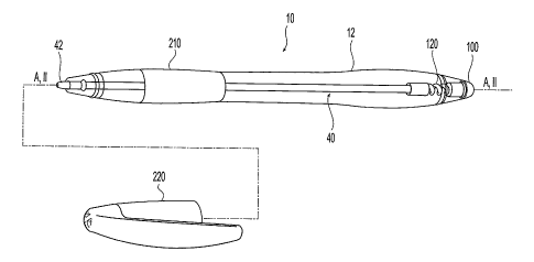
[025] Turning to FIGS. 1 to 5, an embodiment of a writing instrument 10
constructed in accordance with the principles of the present invention is
shown with
the understanding that those of ordinary skill in the art will recognize many
modifications and substitutions which may be made to various elements thereof.
It
will be appreciated that the term "writing" is used herein for the sake of
simplicity.
However, it is to be understood that this is not intended to limit the scope
of the
invention. The terms "writing" or "marking" are not limited to writing and
marking
in their literal sense but, instead should be understood to include
application of other
mediums or substrates such as glue or correction fluid.
[026] As shown in FIGS. 1 and 2, writing instrument 10 generally comprises
a plurality of components, such as barrel 12, cartridge 40, end plug 100, and
longitudinal axis A-A. Cartridge 40 is insertable into barrel 12 and may be
held
within barrel 12 via end plug 100. End plug 100 maybe permanently bonded to
CA 02519530 2005-09-12
WO 2004/082963 PCT/US2004/007744
barrel 12 or releasably attached so that a replacement cartridge 40 may be
inserted
into barrel member 12 when the writing medium therein is depleted (as
discussed in
further detail below).
[027] Cartridge element 40 comprises writing tip 42, main body 44, and
5 proximal, non-writing end 50. Writing tip 42 may be in any desired form,
such as a
roller ball, ballpoint, or nib (e.g., felt or fountain pen). Main body 44
further
comprises writing medium reservoir 52, which may carry writing medium directly
or
in a fibrous wad or tampon. Other types of writing tips and writing mediums
can be
used without departing from the spirit and scope of the present invention. For
instance, writing instrument 10 may use lead or highlighting fluid as a
writing
medium. Proximal end 50 may be provided with opening 54 to allow venting for
writing medium reservoir 52, to allow proper operation of cartridge 40 during
writing
for select types of writing mediums. However, a cartridge not requiring
venting, such
as a pressurized cartridge, may be used instead.
[028] Barrel 12 is generally elongated and cylindrical in shape. Barrel 12
further comprises distal writing end 20, proximal non-writing end 30, and
cavity 14.
Cavity 14 is configured to accept cartridge 40. Distal end 20 has opening 22
configured to allow writing tip 42 of cartridge 40 to protrude from barrel 12.
Proximal end 30 has opening 32 configured to accept end plug 100. In a
preferred
embodiment, the diameter of writing tip 42 is smaller than that of main body
44 of
cartridge 40 and forms a shoulder 60. Projections 70 are formed in barrel 12
adjacent
and proximal to distal end opening 22, against which shoulder 60 of cartridge
40 may
abut, as further described below.
[029] As shown in FIGS. 3 to 5, end plug 100 has an outer end cap 110 and
an inner section 112. Inner section 112 is configured to fit inside barrel 12
and
preferably is also configured to interact with proximal end opening 32 of
barrel 12.
Outer end cap 110 may be shaped and dimensioned to match the outer contour 16
of
barrel 12 and to enhance further the outer visual appearance of writing
instrument 10.
An interference band 114 may be provided encircling end plug 110 where inner
section 112 meets outer end cap 110.
[030] In the embodiment of FIGS. 3-5, end plug 100 is formed integrally with
cushioning element 120. A collar 130 may be integrally formed with cushioning
element 120. In a preferred embodiment, end plug 100, cushioning element 120,
and
collar 130 (if provided) are formed as a single piece. Collar 130 is formed
integrally
CA 02519530 2005-09-12
WO 2004/082963 PCT/US2004/007744
6
with distal end 124 of cushioning element 120, and proximal end 126 of
cushioning
element 120 is formed integrally with distal end 116 of inner section 112.
Collar 130
may be annular in shape, preferably having distal aperture 132 configured to
accept
proximal end 30 of cartridge 40. Cartridge 40 may then be coupled to and held
by
end plug 100 and thereby be stabilized within barrel 12 against wobbling or
movement transverse to the longitudinal axis A-A. In a preferred embodiment,
collar
130 is formed with shoulder 136 against which proximal end 50 of cartridge 40
may
abut such as to be stabilized.
[031] As is well known in the art, some types of cartridges 40 require
venting.
In one embodiment, venting is accomplished through the space between writing
tip 42
and distal writing end opening 22. Furthermore, a proximal aperture 134 may be
provided in collar 130 to allow air to communicate with writing medium
reservoir 52
through proximal end opening 54 of cartridge 40 (see FIG. 11), providing
sufficient
venting of writing medium reservoir 52. Other embodiments of the present
invention
may use alternative ways to provide venting, such as having openings in end
plug 100
or in the side of barrel 12. Still other embodiments may not require venting,
an
example of which would be writing instruments which use pressurized
cartridges.
[032] In a preferred embodiment, writing instrument 10 is assembled by
inserting cartridge 40 into barrel 12 through barrel proximal end opening 32,
and
inserting and attaching inner section 112 of end plug 100 in barrel proximal
end
opening 32. Proximal end 50 of cartridge 40 at least abuts cushioning element
120 or
collar 130. Preferably, proximal end 50 of cartridge 40 is inserted into
collar 130
through distal aperture 132 and thereby held by collar 130. If shoulder 136 is
provided in aperture 132 of collar 130, proximal end 50 of cartridge 40 is
inserted in
aperture 132 to abut shoulder 136 to be thereby stabilized. In a preferred
embodiment, end plug 100 and barrel 12 are fixed with respect to each other so
that
end plug 100 cannot be separated from barrel 12 and accidentally swallowed.
Thus,
end plug 100 and barrel 12 are preferably made of the same material, allowing
them
to be permanently welded together, such as by ultrasonic welding. Interference
band
114 provides sufficient interference between inner section 112 and proximal
end
opening 17 such that an ultrasonic shear weld can be used to attach end plug
100 to
barrel 12 permanently.
[033] Other manners of assembling writing instrument 10 can be used without
departing from the spirit and scope of the present invention. For example,
instead of
CA 02519530 2005-09-12
WO 2004/082963 PCT/US2004/007744
7
proximal end 50 of cartridge 40 being stabilized by abutting collar 130 in
shoulder
134, cartridge 40 may be held by cushioning element 120 by a press-fitting,
threaded,
or adhesive attachment. Also, end plug 100 can be attached to barrel 12 by use
of a
face weld instead of a shear weld, or other attachment means such as press
fitting,
threading, or adhesives. Furthermore, the attachment of end plug 100 to barrel
12 can
be permanent or end plug 100 can be attached releasably from barrel 12 (in
which
case the shape and configuration of end plug 100 is selected to not result in
asphyxiation if swallowed).
[034] Writing tip 42 movably extends through writing end 20 of barrel 12 for
displacement in an axial direction along longitudinal axis A-A into barrel 12.
This
allows writing tip 42 to respond to forces exerted upon it when writing
pressure is
applied to and released from writing tip 42. In response to such forces,
cushioning
element 120 provides a biasing force in the opposing direction against writing
tip 42
through cartridge 40, providing a certain feel to the user of the writing
instrument 10.
Distal end opening 22 is configured to allow minimum clearance between the
walls of
the opening 22 and writing tip 42 in order to prevent deflection of the
writing tip 42
off the longitudinal axis A-A. Furthermore, because cartridge proximal end 50
preferably is inserted into collar 130, deflection or wobbling of cartridge 40
(movement transverse to longitudinal axis A-A) is further prevented.
[035] Preferably, writing instrument 10 is assembled such that there is a
small
preload on cushioning element 120 so that shoulder 60 of cartridge 40
constantly
presses against projections 70 of barrel 12. Therefore, even when the writing
instrument 10 is not in use, cushioning element 120 provides a biasing force
on
cartridge 40 and writing tip 42 in an axial directional along longitudinal
axis A-A
towards distal writing end 20. This helps to prevent the user from
experiencing a
feeling of looseness during use of writing instrument 10. Furthermore, this
preload on
cushioning element 120 ensures that cartridge 40 is constantly pressed against
collar
130 (preferably shoulder 136), further ensuring that cartridge 40 does not
become
separated from collar 130.
[036] Other embodiments of the present invention may allow the user to vary
the amount of preload on cushioning element 120. For example, in a preferred
embodiment, end plug 100 may be attached to barrel 12 via a threaded
attachment,
allowing the user to increase or decrease the amount of preload on cushioning
element
120 by increasing or decreasing the amount that end plug 100 is inserted into
barrel
CA 02519530 2005-09-12
WO 2004/082963 PCT/US2004/007744
8
proximal end opening 32. The more that end plug 100 is inserted into barrel
proximal
end 32, the greater the compression cushioning element 120 experiences from
projections 70 pressing against cartridge shoulder 60, due to the decreased
distance
between projections 70 and the distal end 124 of cushioning element 120.
[037] In a preferred embodiment, cushioning element 120 may take the form
of a spring. It is noted that the geometrical configuration of the cushioning
element
120 depends upon the material used to form the cushioning element 120 and the
desired spring rate. Once a material is selected and the flexural modulus of
the
material is determined, the geometry of cushioning element 120 can be
configured so
as to provide the desired spring rate (force/distance the spring is
compressed) for
cushioning element 120. Therefore, the actual flexural modulus of the material
used
to compose cushioning element 120 is not critical to the present invention. By
increasing or decreasing the thickness and varying the cross-sectional shape
and
orientation of a spring coil, the spring rate can be controlled. The knowledge
of how
to configure cushioning element 120 to provide a desired spring rate is well
known in
the art. In a preferred embodiment, the stiffness of the material and the
spring
configuration of cushioning element 120 is selected to provide a spring rate
of
approximately 0.45 kg/mm. A spring rate of no less than about 0.10 kg/mm and
/or
no greater than 1 kg /mm is generally preferred. However, other spring rates
can be
used without departing from the spirit and scope of the present invention.
[038] If desired, a cushioning element 120 in the form of a spring 120' may
be further configured to have a variable spring rate, as illustrated in FIG.
8. Thus, the
change in the spring rate as the user compresses cushioning element 120
increases in a
non-linear manner (whereas a standard spring has a spring rate that increases
in a
generally linear manner). A variable spring rate may be achieved in any of a
number
of manners known to those of skill in the art. For instance, a coil spring
with varying
distances A, B, C between the adjacent coils thereof may provide a variable
spring
rate. As the spring is compressed, the coils sequentially bottom out, starting
with the
coils that are spaced closer together. Each time adjacent coils bottom out,
the overall
spring rate of the coil spring increases. Thus, as the user presses writing
tip 42 against
a substrate with increasing pressure, the spring provides increased resistance
to the
user's pressing force. Over-compression of the spring may thereby be inhibited
or
avoided. Moreover, the increase in pressure provides feedback to the user and
may
remind the user to apply less pressure to writing tip 42.
CA 02519530 2005-09-12
WO 2004/082963 PCT/US2004/007744
9
[039] In one embodiment, barrel 12 is composed of a transparent material,
allowing cushioning element 120 of end plug 100 to be seen. This enhances the
visual effect of writing instrument 10.
[040] In order to simplify manufacture as well as assembly and to reduce the
number of moving parts, end plug 100 and cushioning element 120 may be formed
integrally by an injection molding process. Cushioning element 120 of such
embodiment, therefore, is configured so that it may be formed by an injection
molding process, as described below.
[041] It is well known in the art that it is extremely difficult to
manufacture a
true helical coil spring by injection molding. The contours formed are too
complex
and are not amenable to being formed in molds that separate along a mating
plane. A
true helical coil spring formed by injection molding generally is damaged as
the
spring is ejected from the mold because of the complexity of the shape. For
example,
as shown in FIG. 6, a helical coil spring 500 has undercuts 510. These
undercuts 510
prevent a helical coil spring from being easily removed from an injection mold
cavity.
[042] Cushioning element 120 of a preferred embodiment of the present
invention is formed so as to have no undercuts which would prevent cushioning
element 120 from being removed from an injection mold. As seen in FIG. 4, a
molded end plug 100 has a distinct parting plane X-X. Each half of cushioning
element 120 along parting plane X-X is composed of spring segments 122, each
spring segment 122 generally being in the shape of half of a torus, preferably
with a
"D" shaped cross-section. As seen from a top view of cushioning element 120
(FIG.
3), there are no undercuts along spring segments 122, as there would be in a
true
helical coil spring. From a top view of cushioning element 120, this results
in a zig-
zag appearance for cushioning element 120.
[043] Exemplary molding equipment that may be used to form end plug 100
is illustrated in FIG. 7. The material from which end plug 100 with cushioning
element 120 is formed may be injection molded into mold halves 300 and 302, as
shown in FIG. 7. Each mold half 300, 302 has outer end cap cavity 310, inner
section
cavity 312, collar cavity 314 (if a collar is provided), and spring segment
cavities 320.
The spring segment cavities 320 of each mold half are not connected with one
another. Mold halves 300 and 302 also have pin cavities 352 which allow pin
350 to
be inserted between mold halves 300, 302 when mold halves 300 and 302 are
mated
together to maintain the desired internal configuration of end plug 100.
CA 02519530 2005-09-12
WO 2004/082963 PCT/US2004/007744
[044] When mold halves 300 and 302 are mated, the respective outer end cap
cavities 310, inner section cavities 312, and collar cavities 314 are lined up
with one
another, and the ends of each of the spring segment cavities 320 of first mold
half 300
are lined up with the ends of two adjacent spring segment cavities 320 of
second mold
5 half 302. Pin 350 is inserted to define the apertures 132 and 134 and
shoulder 136 in
collar 130 and to define the inner portion of spring segments 122. Molten or
at least
flowable material is injected into the mold and cooled or hardened, depending
upon
the material used. Formed end plug 100 is then removed from the mold.
[045] End plug 100 may be composed of SAN (Styrene Acrylonitrile), a
10 thermoplastic polymer. However, many other materials, including other
thermoplastics such as ABS, Styrene, Acetal, polycarbonate, or filled
materials may
also be used. Desirable characteristics of the material used in forming end
plug 100
include the material's ability to be used in mass-production manufacturing
methods,
such as injection molding processes, as well as a relatively high flexural
modulus, or
stiffness. Preferably, the material possesses a flexural modulus above about
100,000
psi. It has been determined that materials having a flexural modulus below
this
amount are for practical purposes too pliant to be used to form cushioning
element
120. Furthermore, while there is theoretically no upper limit to the flexural
modulus
that can be used, it is noted that a flexural modulus of about 500,000 psi is
generally
the upper limit found in most thermoplastic polymers.
[046] Other manners of manufacturing end plug 100 include the use of
stereographic lithography, or the machining of blank forms.
[047] In another preferred embodiment, cushioning element 120 further
comprises travel-limiting projections 400, shown in FIGS. 9 and 10, which
limit the
amount of compression that cushioning element 120 can undertake. The travel
limiting projections 400 prevent over-compression of cushioning element 120,
which
may lead to breakage or undesired permanent deformation of cushioning element
120,
particularly if cushioning element 120 is formed of a material (such as
plastic) that
can take a set or otherwise can deform. Each travel-limiting projection 400
has a
distal end 402 and a proximal end 404. Distal end 402 preferably is slightly
concave,
while proximal end 404 preferably is slightly convex (although the reverse
configuration is acceptable, as well as other configurations or no curvature
at either
end). Once cushioning element 120 is compressed to a certain length, distal
end 402
of each travel-limiting projection 400 abuts proximal end 404 of the adjacent
travel-
CA 02519530 2005-09-12
WO 2004/082963 PCT/US2004/007744
11
limiting projection 400, preventing cushioning element 120 from being
compressed
further. This embodiment may also be formed using the injection molding
process
described above, with the addition of travel limiting projection cavities to
mold halves
300 and 302.
[048] Alternatively, in order to inhibit or to prevent bottoming out of the
cushioning element, a stop element 500 may be provided. Stop element 500
preferably is formed separately from cushioning element. In the exemplary
embodiment of FIGS. 11 and 12, stop element 500 is in the form of a stop pin
extending through a longitudinal channel 502, 504, 506 through cushioning
element
120, end button 100, and collar 130. Stop element 500 preferably has an
enlarged-
diameter end or head 510 at distal end 512 sized to abut proximal end 52 of
cartridge
40. Enlarged-diameter end 510 also may be configured to abut shoulder 514
within
collar 130 to limit the distance stop element 500 can be inserted through
longitudinal
channel 502, 504, 506 for reasons that will become apparent. Stop element 500
is
configured so that stop element 500 does not affect compression of cushioning
element 120 at the beginning of compression of cushioning element 120.
However,
when cushioning element 120 is compressed a predetermined amount, stop element
500 becomes effective and inhibits or prevents further compression of
cushioning
element 120.
[049] In the embodiment of FIGS. 11 and 12, stop element 500 is effective
only after a predetermined amount of compression of cushioning element 120 by
being effectively shorter than cushioning element 120 when cushioning element
120
is in an uncompressed state. Thus, when the length of cushioning element 120
shortens to be substantially equal to the length of stop element 500, stop
element 500
can affect further compression of cushioning element 120. The difference in
length
between stop element 500 and cushioning element 120 thus determines the
duration or
degree to which cushioning element 120 is effective before being influenced or
affected by stop element 500. The difference in length is selected based on a
number
of factors known to those of ordinary skill in the art, such as the spring
constant,
material, and / or configuration of cushioning element 120. The degree or
extent to
which stop element 500 affects the functioning of cushioning element 120 may
be
determined based on subjective user preferences. Thus, if a writing instrument
10
with very little cushioning is desired, then stop element 500 may be formed to
affect
cushioning element 120 very quickly after compressing cushioning element 120.
CA 02519530 2005-09-12
WO 2004/082963 PCT/US2004/007744
12
With reference to the embodiment of FIGS. 11 and 12, to achieve very little
cushioning, the difference in length between stop element 500 and cushioning
element
120 is minimal. Another factor in determining the degree or extent to which
stop
element 500 affects the functioning of cushioning element 120 maybe the yield
point
of the spring. In particular, stop element 500 may be selected and configured
to
interact with cushioning element 120 to prevent the yield point of cushioning
element
120 from being exceeded.
[050] In the embodiment of FIGS. 11 and 12, actuation of stop element 500 is
achieved by leaving a gap 516 in end button 100 between proximal end 518 of
stop
element 500 and closed end 520 of channel 506 within collar 130 when
cushioning
element 120 is in an uncompressed, neutral, rest position (i.e., not actuated
by
pressing cartridge 40 against a substrate). Enlarged-diameter end 510 of stop
element
500 abuts shoulder 514, as noted above, to prevent proximal end 518 from
abutting
closed end 520 of channel 506 when cushioning element 120 is not activated
(e.g., not
compressed). Gap 516 permits compression of cushioning element 120 a given
extent
before cushioning element 120 is compressed to the length of stop element 500.
Once
cushioning element 120 is compressed a predetermined extent, proximal end 518
of
stop element 500 contacts closed end 520 of channel 506 within collar 130 to
inhibit
or to prevent further compression of cushioning element 120.
[051] The dimensions and materials of cushioning element 120, stop element
500, and gap 514 are selected to achieve the desired range of compressibility
of
cushioning element 120 before bottoming out (i.e., before compressibility of
cushioning element 120 is affected by stop element 500). In one embodiment,
gap
516 is approximately 1 mm in length. Because selection of the length of gap
516
affects the degree or extent to which stop element 500 affects the functioning
of
cushioning element 120, such selection may be based on user preference and /
or
engineering aspects, as described above generally with respect to
determination of the
affect of stop element 500 on cushioning element 120. If stop element 500 is
formed
from a relatively rigid material, then once proximal end 518 of stop element
500
contacts closed end 520 of channel 506, further compression of cushioning
element
120 is essentially prevented. However, stop element 500 may be formed from a
material that has some degree of resiliency so that further compression of
cushioning
element 120 is possible even after proximal end 518 of stop element 500
contacts
closed end 520 of channel 506. For instance, stop element 500 may be formed
from a
CA 02519530 2005-09-12
WO 2004/082963 PCT/US2004/007744
13
resilient or compressible or elastomeric or elastomeric-like material, such as
rubber or
thermoplastic elastomers or foams. Of course, if very little further
compression is
desired once stop element 500 becomes effective, then stop element 500 may be
formed form a non-resilient or non-elastomeric material, such as a ferrous or
ceramic
material.
[052] As noted above, proximal end 50 of writing medium reservoir 52 may
be provided with opening 54 to allow venting for writing medium reservoir 52.
Thus,
if proximal end 50 of writing medium reservoir 52 abuts stop element 500, then
stop
element 500 preferably is configured to permit venting as well. As illustrated
in FIG.
12, flats 520 may be formed in enlarged-diameter end 510 of stop element 500.
Thus,
venting of writing medium reservoir 52 may also occur through stop element
500.
[053] According to one aspect of the present invention, in the exemplary
writing instrument described herein, cushioning element 120 and end plug 100
preferably are formed integrally with each other. During the formation of an
integrally formed end plug 100 with cushioning element 120, at least one is
formed of
a moldable material. Thus, cushioning element 120 and end plug 100 are
inseparable
and act as one element once the formation process is complete, requiring no
further
assembly or attachment to each other before use in assembling the writing
instrument.
[054] In some instances, it may be desirable to have a cushioning element
formed of a different material than that of the end plug. The present
invention may be
practiced by forming an end plug with a cushioning element formed integrally,
wherein the cushioning element is formed from a different material from the
material
of the end plug. For example, in another preferred embodiment, end plug 100
may be
formed from a thermoplastic such as SAN, with a cushioning element 120 formed
from a different moldable material, by a two-part molding process, such as a
"two-
shot" or "overmolding" process, both of which are well known in the art. The
cushioning element 120 may also be made of a non-moldable material, such as a
metal, and formed integrally with end plug 100 by an insert molding or
overmolding
process. After the formation of end plug 100 and cushioning element 120, end
plug
100 and cushioning element 120 are inseparable and act as one element,
requiring no
further assembly or attachment to each other before use in assembling writing
instrument 10. In another preferred embodiment, end plug 100 is made of a non-
moldable material, and is formed integrally with cushioning element 120,
cushioning
element 120 being made of a moldable material.
CA 02519530 2005-09-12
WO 2004/082963 PCT/US2004/007744
14
[055] Other additional features can be added to writing instrument 10 without
departing from the spirit and scope of the present invention. For instance, in
a
preferred embodiment, gripping element 210 is added to barrel 12, aiding the
user in
gripping writing instrument 10. Also, cap 220 can be provided to cover distal
writing
end 22 and writing tip 42 when not in use. However, such additional features,
while
desirable, are not necessary to practice the present invention.
[056] The present invention is not limited to only the preferred embodiments
and means of assembly described above. For example, the cushioning element of
the
present invention may be formed integrally with a different element of the
writing
instrument 10, such as a barrel 12 or a front nose cone, instead of end plug
100 as
described in the above preferred embodiment. Other embodiments of the present
invention may use a cushioning element that is stretched during writing,
rather than
compressed as described in the above preferred embodiment. As another example,
other embodiments of writing instrument 10 may be assembled by inserting
cartridge
40 through the distal end 20 of barrel 12, such as for embodiments with a
detachable
front nose cone.
[057] It will be appreciated that these features are separate and independent
aspects of the present invention, each, at least alone, having unique benefits
which are
desirable for, yet not critical to, the present invention. It will also be
appreciated that
features described with respect to one embodiment typically may be applied to
another embodiment, whether or not explicitly indicated. The various features
described herein may be used singly or in any combination thereof. Therefore,
the
present invention is not limited to only the embodiments specifically
described herein.
[058] While the foregoing description and drawings represent the preferred
embodiments of the present invention, it will be understood that various
additions,
modifications and substitutions may be made therein without departing from the
spirit
and scope of the present invention as defined in the accompanying claims. In
particular, it will be clear to those skilled in the art that the present
invention may be
embodied in other specific forms, structures, arrangements, proportions, and
with
other elements, materials, and components, without departing from the spirit
or
essential characteristics thereof. One skilled in the art will appreciate that
the
invention may be used with many modifications of structure, arrangement,
proportions, materials, and components and otherwise, used in the practice of
the
invention, which are particularly adapted to specific environments and
operative
CA 02519530 2005-09-12
WO 2004/082963 PCT/US2004/007744
requirements without departing from the principles of the present invention.
The
presently disclosed embodiments are therefore to be considered in all respects
as
illustrative and not restrictive, the scope of the invention being indicated
by the
appended claims, and not limited to the foregoing description.