Note: Descriptions are shown in the official language in which they were submitted.
CA 02519977 2005-09-22
WO 2004/099510 PCT/US2004/011265
WEAR ASSEMBLY FOR THE DIGGING EDGE OF AN EXCAVATOR
Field of the Invention
The present invention pertains to a wear assembly and particularly for the
attachment of a wear member to the digging edge of a bucket or other
excavator.
Background of the Invention
It is a common practice to secure wear members in the form of teeth and
shrouds
along the digging edge of a bucket or other excavator to protect the front lip
from
premature wear. The teeth project forward of the lip to ease penetration and
break up the
ground to be gathered in the bucket. The shrouds are mounted to the lip
between the teeth.
As can be appreciated, the wear members, and particularly the teeth, are often
placed in
harsh working conditions where they are subjected to very heavy loading and a
high degree
of wearing.
Excavating teeth are generally composed of a multiple of parts including, for
example, an adapter, a point and a lock. The adapter has a rear mounting end
configured
for attachment to the front lip of the bucket, and a forwardly projecting nose
for mounting
the point. The point is a tapered member provided with a forward earth-
penetrating end
and rearwardly opening socket that receives the adapter nose. The lock is fit
within the
wear assembly to hold the point to the adapter. Although the points wear out
most
frequently, the adapters are also subjected to wear and require periodic
replacement.
Adapters are often welded to the bucket lip, such as in U.S. Patent No.
4,577,423 to
Hahn. Although welding securely attaches the adapter to the bucket to
withstand the heavy
loads, the replacement of weld-on adapters is difficult and typically
performed at a shop
rather than in the field. This causes the bucket to be placed out of
commission, which,
particularly in the case of the larger buckets, can result in a serious
economic loss for the
CA 02519977 2005-09-22
WO 2004/099510 PCT/US2004/011265
operator of a mine or other excavating site. Accordingly, the time and
difficulty required
to remove and install such weld-on adapters has proven to be a significant
deterrent.
To enable replacement in the field, adapters have been developed that are
mechanically attached to the bucket lip. The most common is known as a Whisler-
style
adapter (e.g., as shown in U.S. Patent No. 4,267,653 to Hahn). In these
arrangements, the
rear mounting end of the adapter comprises a pair of bifurcated legs which
straddle the
bucket lip. Each leg of the adapter includes an opening that is aligned with a
through-hole
or keyway formed in the lip of the bucket. The rear ends of the legs are
formed with ramp
surfaces that are inclined upward and away from the respective openings. A
spool and
wedge are inserted into the aligned openings and through-hole to secure the
adapter in
place.
More specifically, the spool is generally C-shaped with arms that are
configured to
matingly engage the ramp surfaces of the legs. Insertion of the wedge between
the spool
and the front of the through-hole presses the spool rearward with the arms
riding over the
ramp surfaces of the legs. In this way, the arms pinch the legs against the
inner and outer
surfaces of the lip to secure the adapter in place. The wedge is usually
inserted into the
assembly by repeated blows with a large hammer. This can be an onerous and
time-
consuming task for field workers, especially to achieve the final movement
needed to
adequately hold the adapter to the lip. Further, the wedge even when tightly
inserted can
become loose under heavy loading, thus, risking loss of the adapter. A
significant
contributor to the loosening is actual stretching of the C-shaped spool under
service
loading, such as when the legs of the adapter shift on the lip under heavy
loading. At
times, the wedge is welded to the spool in its tightened position in an effort
to resist such
loosening. This action, however, prevents re-tightening of the lock, which
allows assembly
looseness, resulting in higher stresses in the wear member and a faster rate
of wear on the
2
CA 02519977 2005-09-22
WO 2004/099510 PCT/US2004/011265
lip. The welding together of the wedge and spool also causes removal of the
lock to be
more difficult.
U.S. Patent No. 5,653,048 to Jones et al. discloses another mechanically
attached
adapter. In lieu of a through-hole, a boss is welded along the face of the
lip. The boss is
generally T-shaped and is received in a complementary slot formed in the leg
of the
adapter. An opening is provided at the rear end of the leg for receiving a
lock. The lock,
then, abuts the rear end of the boss and the rear wall of the opening to
prevent the adapter
from sliding forward off the boss and the lip. While this provides good
support for most
teeth, there is a desire for improvement for use in excavator types that
deliver equally large
vertical orientation loads from both the top and the bottom directions.
Summary of the Invention
In the present invention, a wear member is securely attached to the lip of a
bucket
or other excavator by a mechanical means that facilitates easy installation
and removal.
In accordance with one aspect of the present invention, the lip is provided
with a
through-hole and a boss to secure a wear member in place. The boss and wear
member
include a tongue and groove arrangement to support the wear member in
resisting the
applied loads. The through-hole is adapted to receive a lock to prevent
removal of the wear
member from the lip.
In the preferred construction, the boss is positioned at the rear end of the
wear
member to provide enhanced resistance to lateral and/or vertical loading. In
addition, the
lip is formed with a rear member to engage the rear of the wear member and
provide
additional resistance to axial forces. Such added support functions to protect
the lip and
provide it with a longer useful life with less maintenance. Preferably, the
rear member is
formed as part of the boss, to complement the support provided by the boss and
better
stabilize the mounting of the wear member on the lip. Moreover, irrespective
of whether
3
CA 02519977 2005-09-22
WO 2004/099510 PCT/US2004/011265
the rear member functions as an abutment, the rear member is preferably
provided and
fixed to the rails for enhanced support.
The wear member preferably has a pair of rearwardly extending bifurcated legs
that
each includes an inner surface to face the lip, a rear wall, a slot that opens
in the inner face
and the rear wall to receive a boss to resist loads applied during use, an
opening forward of
the slot for receiving a lock to retain the wear member on the lip, and a
lateral wall
extending between the slot and the opening.
In one construction, the bosses are formed to be generally L-shaped with a
stem that
fits into the rear end of the through-hole in the lip, and a main body that
lies along a face of
the lip to cooperate with the wear member. Bosses are preferably provided
along the inner
face and the outer face of the lip to hold the inner and outer legs of the
wear members. The
interconnection of the legs and bosses resists shifting of the legs which in
the past has led
to the stressing, bending and loosening of the locks. Preferably, the bosses
are welded to
the lip and to each other in the through-holes. In this way, a lip formed to
accommodate a
Whisler-style adapter can be easily modified to make use of the present
invention.
In one preferred embodiment, a threaded wedge and spool assembly is used to
secure the wear member in place on the lip. Specifically, a conically shaped
wedge
includes a thread structure that engages a cooperating thread structure on the
spool so that
the wedge is driven into and out of the through-hole via rotation of the
wedge. The use of a
threaded wedge and spool eases installation and removal of the lock, and
reduces the risk
of lock loss during use of the excavator. Moreover, the threaded wedge can be
easily
retightened to keep the wear member snugly mounted on the lip.
In another aspect of the invention, an insert is provided at the front end of
the
through-hole to provide increased bearing support for the wedge through a
longer bearing
length and a higher hardness, less deformable material than is possible in the
lip itself.
4
CA 02519977 2005-09-22
WO 2004/099510 PCT/US2004/011265
The present invention significantly increases the strength and stability of
the wear
member on the lip, leading to longer service life of the wear member and a
reduced
maintenance requirement on the lip. With use of the preferred locking device,
it also
increases ease and safety in fixing wear members to a lip of a bucket or other
excavator.
No large hammers are required to install or remove the lock. The need to work
under the
lip to remove the lock is eliminated. The locks can be removed and installed
quickly and
easily to greatly ease the replacement of the wear members in the field or
elsewhere.
The placement of the boss at the rear of the wear member offers maximum
possible
resistance to vertical and lateral loads applied to the teeth during use. The
abutments
further stabilize the teeth and reduce stress on the front of the lip by
resisting axial loads.
The bosses can be attached to new lips formed to use the bosses or to existing
lips that were
originally constructed to mount Whisler-style adapters. This additional
stability along with
the retightening advantage of the lock reduces the frequency of lip
maintenance and
provides longer adapter service.
Brief Description of the Drawings
Figure 1 is a perspective view of a wear assembly in accordance with the
present
invention.
Figure 2 is a cross-sectional view taken along line II-II in Figure 1.
Figure 3 is a perspective view of a portion of a lip of an excavator with
bosses
attached in accordance with the present invention.
Figure 4 is a perspective view of the two bosses to be attached to the lip.
Figure 5 is a perspective view of a keyway insert in accordance with the
present
invention.
Figure 6 is a rear perspective view of a wear member in accordance with the
present
invention in the form of an adapter.
CA 02519977 2005-09-22
WO 2004/099510 PCT/US2004/011265
Figure 7 is an exploded view of a lock in accordance with the present
invention.
Figure 8 is an enlarged front view of a portion of the spool showing a ratchet
pawl.
Figure 9 is a perspective view showing a wear member partially fit onto a lip
provided with the bosses of the present invention.
Figure 10 is a perspective view of a spool being fit into a wear assembly in
accordance with the present invention.
Figure 11 is a perspective view of a wedge being fit into a wear assembly in
accordance with the present invention.
Figure 12 is partial, rear perspective view of an alternative adapter.
Figure 13 is a perspective view of an alternative outer boss to cooperate with
the
adapter of Figure 12.
Figure 14 is a partial perspective view of the combination of the boss and
adapter
illustrated in Figures 12 and 13 without the lip or inner boss.
Figure 15 is a perspective view of the use of a gauge fixture to retrofit a
lip to use
preferred aspects of the present invention.
Figure 16 is a perspective view of the gauge fixture being used to position
and
attach the bosses of the present invention to a lip.
Figure 17 is a perspective view of the preferred weld pattern in fixing the
bosses
and keyway insert to a lip.
Figure 18 is a perspective view of a wedge of an alternative lock.
Figure 19 is a perspective view of a spool to cooperate with the wedge of
Figure 18
in forming the alternative lock.
Figure 20 is a perspective view of an alternative boss.
6
CA 02519977 2005-09-22
WO 2004/099510 PCT/US2004/011265
Detailed Description of Preferred Embodiments
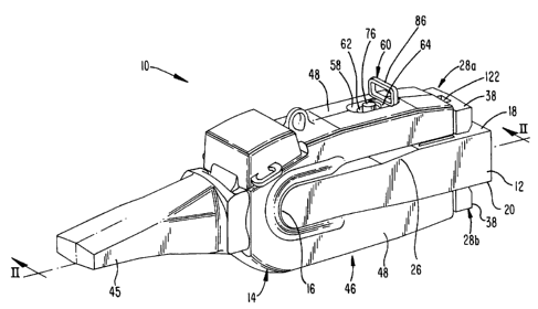
The present invention relates to a wear assembly 10 for mounting a wear member
to
a bucket or other excavator (Fig. 1). The present invention is particularly
suited for
mounting an adapter 14 for an excavating tooth to a lip, but could also be
used to secure
other wear members, such as shrouds. For ease of discussion, the invention
will be
described in terms of mounting an adapter to a lip of a bucket.
In one example, lip 12 defines a digging edge 16 of a bucket, and includes an
inner
face 18 and an outer face 20 (Figs. 1-3 and 9). A front tab 22 preferably
projects forward
from the digging edge to aid in placing and supporting the adapter 14. A
through-hole or
keyway 24 is provided in the lip directly rearward of tab 22. While only a
small portion of
the lip is shown in the drawings, the lip would ordinarily include a series of
spaced apart
tabs and through-holes for the mounting of several teeth to the bucket. In the
illustrated
embodiment, the lip has a rounded digging edge 16 and an expanding region 26
by the
through-holes 24. Nevertheless, many other lip configurations are possible for
use with the
invention.
Bosses 28 are fixed to the lip rearward of and in alignment with each through-
hole
24 (Figs. 1-4 and 9). Preferably, an inner boss 28a is secured to extend along
inner face 18
of lip 12 and an outer boss 28b is secured to extend along outer face 20 for
each through-
hole. Nevertheless, a single boss on the inner face 18 (or outer face 20)
could be used.
Although the bosses are preferably welded to the lip, they could be formed as
an integral
portion of the lip or attached by mechanical means. Also, while the bosses are
preferably
fixed directly adjacent the through-holes 24, they could be spaced rearward of
the through-
holes if desired.
Each boss 28 includes at least a main body 30 that extends in axial alignment
with a
through-hole 24 along either the inner face 18 or outer face 20 of the lip.
The main body
7
CA 02519977 2005-09-22
WO 2004/099510 PCT/US2004/011265
30 preferably has a T-shaped configuration with a base 32 and laterally
extending flanges
or rails 34. The undersides of the rails 34 define holding surfaces 36 that
generally face the
lip to hold the adapter to the lip. Nevertheless, the main body could have
other similar
shapes (such as a dovetail configuration), other formations that provide other
rails or
holding surfaces facing the lip (see, e.g., the later discussed alternative
embodiment in
Figures 12-14), or even a parallelepiped or other shape with no rails or
holding surfaces.
Although a boss with no lateral rails or holding surfaces does not hold the
adapter to the lip
in the same way as a T-shaped boss or the like, it does still provide lateral
support for
resisting the applied loads. Additionally, the tongue and groove arrangement
could be
reversed such that the boss defines the slot that receives a tongue defined by
the wear
member. In this arrangement, the holding surfaces of the boss that resist
outward
movement of the wear member (i.e., away from the lip) still generally face
toward the lip
but are contained in the slot of the wear member.
The bosses are also preferably longitudinally tapered, widening toward the
rear, to
facilitate ease of installation and removal of the wear member. However,
bosses with no
such longitudinal taper are possible, particularly where there is inadequate
space available
to include the taper.
The bosses 28 also preferably each includes a rear member 38 at the rear end
of the
main body 30 to provide enhanced support for the laterally extending rails 34
or the like.
In particular, rear member 38 is fixed to the lip and along the lateral
projections of the rails,
at their rear ends, to strengthen the rails in resisting the applied loads.
When outwardly
extending rails are used (e.g., as in Fig. 3), the rear member is fixed to and
extends laterally
outward of at least part of the main body to provide enhanced support for
rails 34. When
the boss defines the slot, the rails project inward, thus requiring no lateral
outward
extension of the rear member. While rear member 38 can be spaced from the rear
wall 52
8
CA 02519977 2005-09-22
WO 2004/099510 PCT/US2004/011265
of adapter 14 during use, it can also be positioned to abut the adapter (Figs.
1-4 and 9). In
the illustrated embodiment, rear member 38 extends at least laterally beyond
the base 32,
and preferably, also laterally and outwardly beyond rails 34 when abutting
adapter 14 to
maximize the surface area to abut the rear end of the adapter. This abutment
provides
support to resist the applied loads and rearward shifting of the legs so as to
reduce the loads
applied to the digging edge 16 of lip 12. Precluding axial shifting of the
legs also reduces
the stresses imposed on the lock and the risk that the lock will loosen during
use. When
used to abut adapter 14, rear walls 52 of the adapter may be machined to
assure close
positioning of front surface 39 to rear walls 52 when the adapter is first
slid onto the lip and
abuts digging edge 16. By relieving the pounding and stress applied to the
digging edge of
the lip, as compared to a conventional Whisler-style adapter, the lip will
last longer and
require less maintenance during its useful life. Ordinarily, in a conventional
Whisler-style
adapter, the front of the lip suffers considerable abuse and must periodically
be built up
with weld or other material. Although the rear member is preferably formed as
part of the
boss, it could be a separate part secured to or cast integrally with the lip.
As a further alternative, front surface 39a can be provided with wear pads or
inserts
41 to protect the boss 28a. The wear pads are preferably tack welded into
recesses 43 in
front surface 39a of the boss, although other arrangements could be used. The
recesses are
preferred to position and support the wear pads, but the wear pads could be
attached to the
front surface without the recesses. In the preferred embodiment, the tack
welds are burned
off for replacement of the wear pads. In Figure 20, two wear pads 41 are
attached to front
surface 39a - one to each side main body 30a. Nevertheless, other arrangements
using one
or more than two wear pads could be used as desired. Moreover, the entire
front surface
39a could be covered with a wear pad. The wear pads are preferably metal
though other
durable materials are possible. The wear pads could be formed of material that
is softer,
9
CA 02519977 2005-09-22
WO 2004/099510 PCT/US2004/011265
harder or the same as the material of the bosses. For example, the wear pads
may be
composed of a softer metal to reduce the rebound of the wear member due to
impacting the
front surface 39a (Figure 20). The wear pads may also be composed of a harder
metal to
resist wear.
In a preferred embodiment, each boss additionally includes a stem 40 that
extends
into the adjacent through-hole 24. The stem provides greater support for the
boss against
the applied loads, particularly when rear member 38 is formed as an abutment
part of the
boss. The stem also enables the inner and outer bosses 28a, 28b to be welded
to each other
to effect a clamping or gripping of the lip by the bosses and thereby enhance
the strength of
the attachment of the bosses to the lip. To ease this interconnection of
bosses 28a, 28b, the
ends of the two stems, together, preferably form a weld groove 42 to
facilitate a welding
procedure from above the lip of the bucket. The stems are also preferably
welded to the lip
within through-hole 24. Nevertheless, the stems could be omitted, particularly
when used
in environments with less severe loading (see, e.g., Fig. 20).
Adapter 14 is a wear member that is mounted to the lip of a bucket to hold the
earth-penetrating tooth points in place (Figs. 1-2, 6 and 9-11). Adapter 14
includes a
forwardly projecting nose 44 for mounting a point 45 (Figs. 1 and 2), and a
mounting end
46 with bifurcated legs 48 to straddle the lip 12. In the preferred
embodiment, the legs are
of equal length and are each provided with a slot 50 shaped to receive the
inner and outer
bosses 28a, 28b. In the illustrated embodiment (Fig. 6), the slot is T-shaped
to matingly
receive bosses 28. However, the slot could vary so long as the slot shape
still receives the
boss to provide the desired support to resist lateral or outward pressures on
the legs.
Moreover, the shape of the slot can vary depending on the shape of the boss
and the loads
to be resisted. Further, limited advantages can be obtained through the use of
a boss and
CA 02519977 2005-09-22
WO 2004/099510 PCT/US2004/011265
slot on only one of the inner and outer faces 18, 20 of the lip, although
better support is
provided through the use of both bosses 28a, 28b.
As seen in Figure 6, the slots 50 are open in the rear walls 52 of legs 48 to
slidingly
receive the bosses therein. Each said slot 50 preferably includes a recessed
wa1143 spaced
from and facing the respective face 18, 20 of lip 12. A narrowed portion 41
sets between
the recessed wall 43 and the lip to define retaining surfaces 47 to oppose
holding surfaces
36 and retain rails 34 in grooves 59 of slot 50. Each slot 50 preferably
extends forward
only a short distance from rear wall 52; i.e., a distance approximately equal
to the length of
the main body 30 of the boss. In this way, the lateral wall 54 at the front of
slot 50 can abut
the front wall 56 of boss 28 as rear wall 52 of leg 48 abuts rear member 38 to
resist axially
applied loads. By using both the front wall 56 and rear member 38, the surface
area
resisting the loads can be maximized to lower the stress in the wear member 10
and lip 12.
Lateral wall 54 can extend entirely across slot 50 as shown (Figs. 6 and 12)
or only
partially across (not shown). It should, however, be understood that it not
necessary for the
front wall 56 of main body (or front member) 30 or the front wall 39 of rear
member 38 to
abut the adapter 14.
In another embodiment (Figs. 12-14), an alternative adapter 49 includes slots
51
without a T-shape or similar construction. Specifically, slots 51 and bosses
53 have
complementary, generally flat sidewalls 55, 59 that extend generally
perpendicular to the
faces 18, 20 of the lip. In place of flanges or rails 34 along the sides of
the bosses, bosses
53 include a forwardly projecting flange or overhang 61 spaced from the
respective lip 18,
20. Fingers 63 project rearward from rear ends 65 of adapter legs 67 to fit
between flange
61 and lip 12 to prevent outward movement of the adapter legs 67 relative to
lip 12, and
thereby support the legs against heavy upward or downward directed loads
applied to the
point. In addition, the rear ends 65 of legs 67 and rear ends 69 of fingers 63
preferably
11
CA 02519977 2009-03-30
abut front faces 71 of boss 53 to reduce the loads applied to digging edge 16
of lip 12, but could
be formed with a gap to avoid such abutment. Nevertheless, as noted above,
fingers 63 and
flanges 61 could be omitted so that there are no transverse holding surfaces
to resist the legs
moving away from the lip.
As can be. appreciated, the primary loads on the teeth are applied at the
earth-penetrating
front ends of the points. As the teeth are forced through the ground, the
points are subjected to
loads of varying intensity, kind, and direction. As a result, many of the
applied loads press on
the points at angles to the longitudinal axis of the tooth. Hence, large
forces are applied to the
adapter holding the point to the bucket. By fitting the rear ends of legs 48
over the fixed bosses
28 (Figs. 1 and 2), the bosses are able to effectively resist the reaction
forces in all directions
with bosses shaped with rails or other holding surfaces and at least in
lateral directions with
bosses without rails or holding surfaces. In the preferred embodiment, the
bosses function in
cooperation with lip pads 57 to support the legs, but, alternatively, they can
provide the entire
support for the back ends of the adapter legs.
A hole or opening 58 extends through each leg 48 forward of slot 50 to receive
a lock
60 (Figs. 1-2, 7-8 and 10-11). Lock 60 is described in detail in copending
Canadian Patent
Application File No. 2,519,984 entitled Releasable Coupling Assembly filed
April 29, 2004,
which may be referred to for further details.
Briefly, lock 60 includes a wedge 62 and spool 64 that are threadedly coupled
together
to tightly hold the adapter to the lip. Wedge 62 has generally a frusto-
conical shape with a
helical groove 66 forming a thread formation. The spool 64 has a generally C-
shaped
configuration with two arms 68 and a channel 70 adapted to receive a portion
of the wedge. The
channel includes spaced apart helical ridge segments 72 to form a thread
formation to complement
helical groove 66. As the wedge is rotated, the engaged thread
12
CA 02519977 2005-09-22
WO 2004/099510 PCT/US2004/011265
formations cause the wedge to move axially along the spool, and hence, into
and out of the
aligned openings 58 and through-hole 24. A recess 74 with flats is provided in
one end of
wedge 62 for engaging a wrench. A rubber cap 76 can be fit into the recess 74
during use
to prevent earthen fines from becoming embedded therein.
A resiliently biased pawl 78 (Fig. 8) is preferably provided in the spool to
engage a
series of ratchet teeth (not shown) formed in the helical groove. The pawl is
preferably
formed in channel 70 along one of the ridge segments, although it could be
formed in other
wall surfaces adjacent wedge 62. In any event, pawl 78 engages the teeth as
the wedge is
rotated such that the wedge can be turned to drive the wedge into the through-
hole 24 but
prevented from turning in a direction that drives the wedge out of the through-
hole. The
pawl can be broken by application of a wrench on wedge 62 to remove the wedge
from the
assembly.
In use, spool 64 is inserted into openings 58 and through-hole 24 such that
surfaces
80 along shank portion 81 abut the front face 82 of lateral wall 54 (Figs. 2
and 10). As
seen in Fig. 2, openings 58 each preferably includes a pocket 83 for receiving
arms 68. In
this way, the spool is anchored to prevent the spool from moving as the wedge
is rotated.
Nevertheless, other arrangements besides the use of arms 68, such as flanges
on the
adapter, could be used to secure the spool in the assembly. With such other
securing
means, arms 68 could be omitted. A handgrip 86 is provided for the operator to
position
and temporarily hold the spool in place while the wedge is inserted. Once the
spool is in its
proper position, the wedge is inserted into channel 70 and turned to drive the
wedge tightly
into place (Fig. 11). While the wedge can abut directly against the front end
88 of through-
hole 24 (Fig. 2), a keyway insert 90 is preferably welded into place at the
front of through-
hole 24.
13
CA 02519977 2005-09-22
WO 2004/099510 PCT/US2004/011265
Keyway insert 90 preferably has a generally C-shaped configuration with a
central
body 92, an inner flange 94 and an outer 96 flange (although other shapes are
possible).
Inner and outer flanges 94, 96 overlie and are welded to the inner and outer
faces 18, 20,
respectively, of lip 12. The rear surface 98 of central body 92 is preferably
arcuate to
receive the front side of wedge 62. Keyway insert 90 functions to provide a
longer and
more deformation resistant bearing surface for wedge 62. Also, it provides a
maintenance
advantage in that it can be replaced, whereas, weld re-building of the keyway
is not only
difficult, but can actually result in a failure of the lip due to the heat
affects of welding in a
high stress zone.
The threaded wedge and spool could be replaced with a conventional fluted
wedge
101 (Fig. 18) and fluted spool 103 (Fig. 19) where the wedge is hammered into
place.
Alternatively an unthreaded wedge (not shown) having the same conical shape or
a
generally block shape (i.e., with generally flat walls) could be used. In the
case of the
conically shaped wedge, the channel in the spool would be formed without the
ridge
segments and the pawl (not shown). In the case with flat wedge walls, the
spool (not
shown) would be modified to provide a generally flat front surface instead of
channel 70.
The unthreaded wedges would in either case be hammered into place as is common
with a
lock for a conventional Whisler-style adapter.
Adapter 14 further preferably includes a central groove 102 along inner
surfaces
104 of legs 48 and bight portion 106. The central groove is adapted to fit
about tab 22 for
additional support of the adapter. The central groove also accommodates keyway
insert 90
during axial sliding of the adapter onto and off of the lip. The bight portion
106 is
preferably built up with an outer lip 108 to provide greater support and a
larger surface area
in contact with the digging edge 16 of lip 12.
14
CA 02519977 2005-09-22
WO 2004/099510 PCT/US2004/011265
The present invention is amenable to being used with existing lips initially
constructed to be used with conventional Whisler-style adapters. In these
situations, it may
be necessary to adapt the lip to better accommodate the attachment of adapters
14. A
gauge fixture 110 as shown in figures 15 and 16 can be slid over the lip and
bayonet 116
inserted to determine where the lip should be built up. In particular, it may
be desirable to
build up the digging edge 16 and pads 57 with weld material until they contact
front
portions 112 and rear portions 114 of gauge fixture 110. It may also be
desirable to grind a
radius around the inner and outer edges of through-hole 24. Bosses 28 are
positioned by
legs 118 of gauge fixture 110 with stems 40 in through-hole 24 and rear member
38 against
the rear ends 120 of gauge fixture 110. The bosses are preferably welded to
lip 12 along
the sides and rear surface of the rear member 38, to each other via notch 42,
and to the lip
along the stems 40 in through-hole 24. The main bodies 30 of bosses 28 may
also, if
desired, be welded along lip 12. The keyway insert 90 is also placed into
through-hole 24
at its front end, and welded to lip 12 along the front ends of flanges 94, 96,
keeping the
weld away from the high stress region of the through hole.
In assembly, the adapter is rearwardly slid onto the bucket with one leg 48 to
each
side of the lip 12 so that bosses 28 are received into slots 50. The rearward
movement of
adapter 14 continues until bight portion 106 abuts digging edge 16. In the
preferred
construction, the front wall 54 of slot 50 abuts against boss 28 and/or rear
wall 52 against
rear member 38 only after wear begins to develop due to use of the bucket.
Nevertheless,
if desired, these other surfaces could be formed as the first abutting face
instead of bight
portion 106. Once the adapter is properly positioned, lock 60 is inserted into
openings 58
and through-hole 24. Specifically, spool 64 is placed with arms 68 resting on
ledges 73 of
opening 58. Wedge 62 is, then, threaded into the assembly by engaging groove
66 with
ridge segments 72 and turning the wedge about its axis. The threading
continues until the
CA 02519977 2005-09-22
WO 2004/099510 PCT/US2004/011265
wedge tightens to a set level of torque. Paw178 engages the ratchet teeth in
groove 66 and
holds the wedge in a locked, tightened condition. Cap 76 is preferably placed
in recess 74
to prevent fines from becoming impacted in the recess.
To remove the adapter, the cap is first removed to permit a wrench to be fit
in
recess 74. The wedge is turned to drive the wedge upward so that it can be
lifted out of the
assembly. The spool 64 is removed from the assembly. Adapter 14 can then be
pulled
from the lip. If the adapter is stuck in place, a pry tool (not shown) can be
inserted into
hole 122 and pulled to pry adapter 14 from lip 12.
The above discussion concerns the preferred embodiments of the present
invention.
Various other embodiments as well as many changes may be made without
departing from
the spirit and broader aspects of the invention as defined in the claims.
16