Note: Descriptions are shown in the official language in which they were submitted.
CA 02520067 2011-10-13
Method and System for the Derivation of Human Gait Characteristics and
Detecting Falls Passively from Floor Vibrations
BACKGROUND OF THE INVENTION
Gait analysis has many applications ranging from rehabilitation to sports
medicine,
15 orthopedics and studying the effectiveness of prosthetics to improve their
design. See Joseph
C, Andrew G., "Gait Analysis in the Amputee: Has it Helped the Amputee or
Contributed to
the Development of Improved Prosthetic Components?" Gait Posture (1996) 4, 258-
68, of
which is hereby incorporated by reference herein in its entirety. Long-term in-
home gait
monitoring not only can provide a measure of a person's functional ability,
but it also can
20 provide a measure of activity levels and may therefore help `evaluate' a
person's health over a
long period of time. Passive in-home gait monitoring can be useful for
assessing healing/
deterioration following therapeutic interventions including surgeries, drug or
physical
therapy. Moreover, the ability to identify negative trends of subtle changes
in a person's gait
can contribute to detection of health problems at early stages of disease
onset. Research also
25 indicates that certain gait characteristics can be used as a biometric for
identification
purposes. See Little J, Boyd J., "Recognizing People by Their Gait: the Shape
of Motion,"
Videre, Winter 1998, of which is hereby incorporated by reference herein in
its entirety. See
On R, Abowd G., "The Smart Floor: A Mechanism for Natural User Identification
and
Tracking Conference on Human Factors in Computing Systems," April 2000, of
which is
30 hereby incorporated by reference herein in its entirety.
l
CA 02520067 2005-09-22
WO 2004/092744 PCT/US2004/009098
On the other hand, falls are a major cause of morbidity in the elderly. See
Frangois P,
Helene C, Rejean H, David W., "Gait in the Elderly," Gait and Posture (1997)
5(2), 128-135,
of which is hereby incorporated by reference herein in its entirety. They are
responsible for
70 percent of accidental'deaths in persons 75 years of age and older. The
elderly, who
represent 12 percent of the population, account for 75 percent of deaths from
falls. See
George F., "Falls in the Elderly," American Family Physician, Apr. 2000, of
which is hereby
incorporated by reference herein in its entirety. The considerable cost
involved in the
treatment and Hospitalization of fall injuries and even death due to falls
could be greatly
reduced if falls could be predicted and avoided through appropriate
intervention. An in-home
gait-monitoring tool with the ability to distinguish between normal walking
and abnormal gait
may help predict a propensity for injurious falls. See Stalenhoef PA,
Diederiks JP,
Knottnerus JA, Fester AD, Crebolder HF., "A Risk Model for the Prediction of
Recurrent
Falls in Community-Dwelling Elderly: a Prospective Cohort Study," J Clin
Epidemiol 2002
Nov;55(11):1088-94, of which is hereby incorporated by reference herein in its
entirety. See
Azizah Mbourou G, Lajoie Y, Teasdale N., "Step Length Variability at Gait
Initiation in
Elderly Fallers and Non-Fallers, and Young Adults," Gerontology. 2003 Jan-Feb;
49(1):21-6,
of which is hereby incorporated by reference herein in its entirety.
Human gait analysis entails numerous parameters that can be classified into
spatio-
temporal, kinematic and kinetic characteristics. Spatio-temporal parameters'
include average
walking velocity, stride length, step length, step time, cadence, stance phase
time, swing
phase time, single support (when only one foot is in contact with the floor),
double support
(when both feet are in contact with the floor), and stride width. Kinematic
parameters study
the angles between the ankle, hip and knee joints. Finally, kinetic analysis
examines
moments, energy and power at these joints. See Craik R, Oatis C., "Gait
Analysis Theory and
Application," Mosby 1995, of which is hereby incorporated by reference herein
in its entirety.
Most gait analysis laboratories use visual means for gait analysis where
kinematic
(See Dockstader S, Tekalp A., "A Kinematic Model for Human Motion and Gait
Analysis,"
Proc. of the Workshop on Statistical Methods in Video Processing (ECCV),
Copenhagen,
Denmark, 1-2 June 2002, pp. 49-54, of which is hereby incorporated by
reference herein in its
entirety) and biomechanical models (See Simon J, Metaxiotis D, Siebel A, Bock
H, Doderlein
L., "A Multi-Segmented Foot Model," 6th Annual Gait and Clinical Movement
Analysis'
2
CA 02520067 2005-09-22
WO 2004/092744 PCT/US2004/009098
Meeting, Shriners Hospitals for Children, Northern California, of which is
hereby incorporated
by reference herein in its entirety) are built from visually acquired gait
data. A review of the
various visual human motion and gait analysis techniques can be found in the
Aggarwal J, and
Cai Q. article (See Aggarwal J, Cai Q., "Human Motion Analysis: A Review,"
Proceedings,
IEEE Nonrigid and Articulated Motion Workshop, Jun. 1997, of which is hereby
incorporated
by reference herein in its entirety.) and Gavrila D. article (See Gavrila D.,
"The Visual
Analysis of Human Movement: A Survey," Computer Vision and Image
Understanding, 73(1):
82 - 98, Jan. 1999, of which is hereby incorporated by reference herein in its
entirety.) An
excellent overview of in-the-lab gait analysis tools, methods and applications
in rehabilitation
can be found in the DeLisa J. article (See DeLisa J., "Gait Analysis in the
Science of
Rehabilitation," VARD Monograph 002, 1998, of which is hereby incorporated by
reference
herein in its entirety.). Gait lab equipment and analysis techniques yield
excellent and detailed
gait characteristics and enable clinicians to prescribe an appropriate
intervention. However,
the equipment required for a functional gait laboratory is extremely
expensive, in the range of
tens of thousands to a few hundred thousand dollars in equipment and software.
Additionally,
the computational power required for the image based analysis make
longitudinal in-home gait
monitoring using these technologies impractical. Moreover, people are normally
referred to
gait labs for full gait analysis only after the changes in their gait have
become obvious. Gait
Laboratories also use pressure measurement systems such as force plates for
gait analysis.
Force plate data can reveal important information such as a quantitative
evaluation of the
effect of Total Knee Arthoplasty (TKA) in patients with osteoarthritis. See
Otsuki T, Nawata
K, Okuno M., "Quantitative Evaluation of Gait Pattern in Patients With
Osteoarthritis of the
Knee Before and After Total Knee Arthoplasty. Gait Analysis Using a Pressure
Measuring
System," Journal of Orthopaedic Science, 4(2): 99-105, 1999, of which is
hereby incorporated
by reference herein in its entirety. The pressure system measured Stance phase
timing and
forces. However, research at the Ohio State University demonstrated that force
plate size
influenced valid gait data acquisition (See Oggero E, Pagnacco G, Morr DR,
Berme N., "How
Force Plate Size Influences the Probability of Valid Gait Data Acquisition,"
Biomedical
Sciences Instrumentation, 35:3-8 1999, of which is hereby incorporated by
reference herein in
its entirety) and that some subjects must alter their gait for valid gait data
acquisition (See
Oggero E, Pagnacco G, Morr DR, Simon SR, Berme N., "Collecting Valid Data From
Force
3
CA 02520067 2005-09-22
WO 2004/092744 PCT/US2004/009098
Plates: How Many Subjects Must Alter Their Gait?" North American Congress on
Biomechanics 2000, of which is hereby incorporated by reference herein in its
entirety.).
Current outside the lab gait analysis techniques broadly fall under three
categories
depending upon the type of device used, wearable devices, walk on devices and
visual gait
analysis tools and techniques. Wearable devices include actigraphs and devices
such as that
described in the gait activity monitor to Smith et al. (See U.S. Patent
5,485,402 to Smith et
al., entitled "Gait Activity Monitor," of which is hereby incorporated by
reference herein in
its entirety.) These devices measure acceleration resulting from movement of
the body or
limb that may not necessarily correspond to walking. Moreover, accelerometers
do not
provide enough information to enable the evaluation of the actual
characteristics of the gait.
The gait activity monitor described in Weir et al. (See U.S. Patent 5,831,937
to Weir et al.,
entitled "Portable Ranging System for Analyzing Gait;" of which is hereby
incorporated by
reference herein in its entirety.) is worn on the ankle with built-in optical
communication.
Another variation on this type of devices is described in Portable Ranging
System, where a
combination of ultrasound and infrared is used to periodically determine the
distance between
a person and a base station (See U.S. Patent 5,623,944 to Nashner, entitled
"Method for
Characterizing Gait," of which is hereby incorporated by reference herein in
its entirety; this
device is mainly used to measure velocity). Walk-on gait analysis devices
include treadmills
(See U.S. Patent 5,952,585 to Trantzas et al., entitled "Portable Pressure
Sensing Apparatus
for Measuring Dynamic Gait Analysis and Method of Manufacture;"of which is
hereby
incorporated by reference herein in its entirety), mats (See Patent 6,360,597
B1 to Hubbard,
Jr., entitled "In-Shoe Remote Telemetry Gait Analysis System, of which is
hereby
incorporated by reference herein in its entirety), special shoes (See
Classification of Gait
Abnormalities: http://guardian.curtin.edu.au/cga/faq/classification.html, of
which is hereby
incorporated by reference herein in its entirety.), and specially designed
floors (See On R,
Abowd G., "The Smart Floor: A Mechanism for Natural User Identification and
Tracking
Conference on Human Factors in Computing Systems," April 2000, of which is
hereby
incorporated by reference herein in its entirety.). The treadmill described in
`Method for
characterizing gait' (See Gavrila D., "The Visual Analysis of Human Movement:
A Survey,"
Computer Vision and Image Understanding, 73(1): 82 - 98, Jan. 1999, of which
is hereby
incorporated by reference herein in its entirety.) has transducers mounted
below the movable
4
CA 02520067 2011-10-13
surface that can measures force from each foot individually can differentiate
between
walking and running. Arrays of pressure sensors are placed under a flexible
mat sheet
are described in (See U.S. Patent 5,952,585, of which is hereby incorporated
by
reference herein in its entirety.) to measure force and other gait parameters.
Another
approach (See U.S. Patent 6,360,597, of which is hereby incorporated by
reference
herein in its entirety), describes an in-shoe pressure sensing system with an
external
telemetry transmitter. The pressure sensor data is transmitted to a remote
computer for
analysis. Another potential method for gait analysis is to have a 'smart
floor'
comprising force plate tiles or embedding load cells under individual tiles
(See Orr R,
Abowd G., "The Smart Floor: A Mechanism for Natural User Identification and
Tracking Conference on Human Factors in Computing Systems," April 2000, of
which is hereby incorporated by reference herein in its entirety.) to measure
characteristics of footsteps; this approach is expensive.
BRIEF SUMMARY OF INVENTION
The present invention passive gait monitor system and method described in
this disclosure are based on detecting vibrations generated by a person or
animal
walking on the floor. An embodiment is implemented using an ultra sensitive
optic-
fiber sensor that is capable of detecting subjects from over ten feet away
from the
sensor on both carpeted and uncarpeted wooden and concrete floors. However,
the
methods described can be applied to other vibration, acceleration, and/or
deflection
sensors and sensing technologies, including but not limited to piezoelectric,
electromechanical, optic, laser, and fiber optic sensors. The vibration,
acceleration,
and/or deflection sensor can be fixed in a corridor or a walkway within the
home
environment or any desired environment, for short term and extended term
monitoring of changes in gait mode and drifts in cadence that may indicate a
heightened fall risk, as well as actual fall. Since it can be deployed in
natural settings
and the user does not need to wear any devices, walk on special surfaces or be
observed by cameras, this gait monitor is completely passive and unobtrusive;
hence,
the "white coat" stress effect associated with a clinical test could be
reduced or even
totally eliminated.
5
CA 02520067 2005-09-22
WO 2004/092744 PCT/US2004/009098
The device and method can detect falls and can be augmented to automatically
initiate
an alert call to designated care providers or emergency services in the event
of a detected fall
episode followed by a period of inactivity.
Other. applications include unobtrusive gait analysis in clinical settings.
One can
envision the deployment of such a monitor in a corridor within the clinic,
where a person's
gait is preliminarily evaluated as he/she enters the clinic and that the
analysis report is
available to the clinician by the time the patient walks into the examination
room.
Longitudinal data, together with more elaborate analysis techniques lead to a
fall prediction
model. Other data may include, for example, pattern recognition or
identification
determination of the subject (human or animal) being monitored. An embodiment
of the
sensing unit of the passive gait monitor is physically small, low-cost, and
designed to transmit
acquired data via hardwired or wireless means. Thus, this embodiment of this
passive gait
monitor maybe ideally suited to monitoring the `natural gait' of a person
during regular
activity, in the home or in the clinic, to provide basic but essential gait
characteristics.
Results obtained from a prototype design and detection algorithms applied to
recorded
raw sensor data demonstrate that this device provides a wide range of
different applications,
including biometrics.
An aspect of an embodiment of the present invention provides a gait monitoring
for
monitoring gait characteristics of a subject. The system comprising: a sensor
module that
detects floor acceleration, vibration, and/or deflection to provide
acceleration, vibration,
and/or deflection signal; and a processor module that analyzes the
acceleration, vibration,
and/or deflection signal for determining gait characteristics.
An aspect of an embodiment of the present invention provides a method for
monitoring gait characteristics of a subject. The method comprising: detecting
floor
acceleration, vibration, and/or deflection to provide acceleration, vibration,
and/or deflection
signal; and analyzing the acceleration, vibration, and/or deflection signal
for determining gait
characteristics.
An aspect of an embodiment of the present invention provides a computer
program
product comprising computer usable medium having computer logic for enabling
at lease one
processor in a computer system or the like to monitor gait characteristics of
a subject. The
computer logic comprising: detecting floor acceleration, vibration, and/or
deflection to
6
CA 02520067 2005-09-22
WO 2004/092744 PCT/US2004/009098
provide acceleration, vibration, and/or deflection signal; and analyzing the
acceleration,
vibration, and/or deflection signal for determining gait characteristics.
These and other objects, along with advantages and features of the invention
disclosed
herein, will be made more apparent from the description, drawings, and claims
that follow.
BRIEF SUMMARY OF THE DRAWINGS
The foregoing and other objects, features and advantages of the present
invention, as
well as the invention itself, will be more fully understood from the following
description of
potential embodiments, when read together with the accompanying drawings. in
which:
FIG.1 is a schematic block diagram of the subject and gait monitoring system.
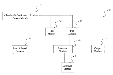
FIG. 2 is a schematic block diagram of the gait monitoring system.
FIGS. 3(A)-(B) are schematic plan and elevation views, respectively, of an
embodiment of the present invention acceleration, vibration, and/or deflection
module.
FIGS. 3(C)-(D) show a graphical representation of the "raw" and post
processing
signals produced in the embodiment of FIGS. 3(A)-(B), wherein the steps are as
captured in
FIG. 3(D) while the raw signal shows the rich harmonic content as captured in
FIG. 3(G).
FIG. 4 is a schematic block diagram of an example of the gait monitoring
system.
FRG. 5 shows a graphical representation of an example of the results obtained
applying an exemplary circuit model to the data obtained from the floor
vibration sensor for a
normal walk.
FIG. 6 shows a graphical representation of an example of the results obtained
applying an exemplary circuit model to the data obtained from the floor
vibration sensor for a
limp.
FIG. 7 shows a graphical representation of an example of the results obtained
applying an exemplary circuit model to the data obtained from the floor
vibration sensor for a
shuffle.
FIG. 8 shows a graphical representation of an example of the results obtained
applying an exemplary circuit model to the data obtained from the floor
vibration sensor for a
fall.
FIG. 9 shows the graphically shows an example demonstrating the fall
detector's
7
CA 02520067 2005-09-22
WO 2004/092744 PCT/US2004/009098
reduced sensitivity to falling objects.
DETAILED DESCRIPTION OF THE INVENTION
The floor vibration sensor employed in any embodiment of the gait monitor can
be
any variety of sensor modalities including, but not limited to: magnetic coil
induction; laser
light reflection; changes in Plasmon surface resonance; RF; changes in light
due to
luminescence; Doppler radar; and/or any sensor technology that transduces the
minute
deflections of the floor induced by gait or falling or dropping of objects.
The slightest vibrations imparted on the active sensor element either directly
or
through but not limited to mechanical, acoustic or optical means yield a
signal that varies in
an analog of the floor vibration or displacement. The sensor element may be
attached to any
surface including but not limited to the floor itself, the baseboard of a
wall, a wall, the ceiling,
and below the floor. The sensor element may be freestanding, using
displacement against
moment of inertia of the system or where displacement is determined by
difference between
the modulating surface and another plane including but not limited to the
baseboard of a wall,
a wall, the ceiling, and below the floor. Various support electronics may be
used to provide
detection, amplification and filtering of the transduced signals.
Moreover, it should be appreciated that the vibration sensor employed in any
embodiment of the gait monitor may be various optic sensors, for example such
fiber optic
sensors as employed in U.S. Patent 6,687,424 B1 to Gerdt et al., entitled
"Sensing Pad
Assembly Employing Variable Coupler Fiberoptic Sensor;" U.S. Patent 6,463,187
B 1 to
Baruch et al., entitled "Variable Coupler Fiberoptic Sensor and Sensing
Apparatus Using the
Sensor;" U.S. Patent Application Publication 2003/0199771 Al to Baruch et al.,
entitled
"Apparatus and Method for Measuring Pulse Transit Time;" of which are hereby
incorporated
by reference herein in their entirety. Other available fiber optic sensors may
be employed as
well and can be any variety of sensor modalities.
Referring to FIG. 1, the sensing unit or module 32 is configured so that it
can measure
floor 35 vibrations. The sensor module 32 can pick-up floor vibrations
generated by a person
or subject 33 (or animate or inanimate object) walking tens of feet away (or
any distance
required for setting or environment) from the sensor on both carpeted and
uncarpeted wooden
8
CA 02520067 2005-09-22
WO 2004/092744 PCT/US2004/009098
and concrete floors (or any given platform or base). As will be discussed in
greater detail
below, an embodiment of the present invention system processes the raw
vibration signal of
the sensor system and extracts features of significance and analyzes the
extracted data to
provide basic gait characteristics. In an embodiment, the processor module 40
analyzes or the
like performs algorithms or manipulation to differentiate between normal gait,
limping and
shuffling and measure step count and calculate cadence with good accuracy when
the gait is
normal. A rate of travel detector module 44 is provided to track the motion or
travel span of
the subject 33.
Referring to FIG. 2, FIG. 2 is a schematic block diagram of the gait
monitoring
system and related method for monitoring gait characteristics of a subject
(person, animal,
animate or inanimate object). An embodiment of the present invention system 31
includes a
sensor acceleration, vibration, and/or deflection module 32 that detects floor
acceleration,
vibration, and/or deflection to provide the acceleration, vibration, and/or
deflection signal.
Examples include but are not limited to magnetic coil induction; laser light
reflection;
changes in Plasmon surface resonance; RF; changes in light due to
luminescence; doppler
radar; and/or any sensor technology that transduces the minute deflections of
the floor
induced by gait or falling or dropping of objects. A processor module 40 is
provided that
analyzes the acceleration, vibration, and/or deflection signal for determining
gait
characteristics data obtained by the sensor module 32. The system 31 and/or
processor 40 is
in communication with an output module 52 for receiving the gait
characteristics data.
Examples of the output module 52 include at least one of the following, but
not limited
thereto, display, alarm, memory storage, communication device, printer,
buzzer, PDA, lap top
computer, computer and/or light; or any available device required for
input/output. Examples
of the communication device include at least one of the following, but not
limited thereto,
modem, pager, network interface, Ethernet card, serial communications port,
parallel
communications port, telephone, and/or a PCMCIA slot and card; or any other
available
device required for communication.
Still referring to FIG. 2, it should be appreciated that the system 31 or only
portions of
the system or communication paths of the system 31 (or with external devices)
may be
hardwired, wireless, or combination thereof. Examples of wireless
communication include at
least one of the following, but not limited thereto, RF link, BLUE TOOTH, an
infrared,
9
CA 02520067 2005-09-22
WO 2004/092744 PCT/US2004/009098
cellular phone link, optical and/or electromagenetic; or any other available
wireless
communication. Alternatively, the system 31 or only portions of the system or
communication paths of the system 31 (or with external devices) may be hard
wired,
mechanical, optical, or optical-mechanical, electro-mechanical communication.
Some
examples of communication include at least one of the following, but not
limited thereto,
integrated circuits, wire, cable, fiber optics, a phone line, twisted pair,
and/or coaxial; or any
mechanism capable of communication transmission.
Still referring to FIG. 2, an embodiment of the system may include at least
one rate-
of-travel detector or module 44 to determine the rate of travel of the
subject. For example,
1o the rate-of-travel detector may be any one of a system of beam breaks,
floor switches, and
door switches or any available systems capable to track the motion, movement,
or travel span
of the subject. The rate-of-travel detector may operate in various modes
including one of
ultrasonic communication, IR communication, laser communication, ground radar
communication, wide band radar communication, and/or doppler communication; or
any
other communication path or via necessary to effect the travel or motion
detection.
Still referring to FIG. 2, an embodiment of the system may include at least
one fall
detector or module 36 that analyzes fall related data and at least one step
module 48 that
analyzes step related data. The module uses analog, digital or hybrid signal
processing to
reduce the raw signal for analysis and derivation of characteristics including
but not limited to
physical forces that are currently known in gait such as heel toe impact, heel
rotation, forces
generated when the toes push off the floor to get locomotion (e.g.
gastricnemeous
contraction), knee flexure, hip rotation, and pelvis swivel, etc. These
individual force
generators may be integrated into the amount of forward motion that is
generated, versus the
amount of motion that is spent lifting the body. The processor module 40 can
provide
numerous functions and operations including, but not limited to: analyzing the
acceleration,
vibration, and/or deflection signal for determining gait characteristics data
obtained by the
sensor module 32 and other components and modules of the system 31 or data or
information
received externally. The gait characteristics of the subject includes at least
one of, but not
limited thereto, step count, pace, normal condition, limp, shuffle, falls,
average walking
velocity, step length, and/or stride length; or any other necessary parameter
required or
desired for a given application.
CA 02520067 2005-09-22
WO 2004/092744 PCT/US2004/009098
Still referring to FIG. 2, an embodiment of the system may include at least
one
archival storage / memory 54. The archival storage / memory 54 stores at least
one of
longitudinal analysis of gait characteristics, pattern recognition, and/or
identification
determination; or other data as required or desired for given application.
Further, the
processor module 40 or other secondary processors analyzes the gait
characteristics, pattern
recognition, and/or identification determination data. In an embodiment the
system further
comprises a second processor module (not shown). The second processor module
may be
configured to analyze the gait characteristics, pattern recognition, and/or
identification
determination data; or other data as required or desired for given
application.
Herein provided are illustrative embodiments to demonstrate specific examples
of the
present invention method and system, or components of the system. These
exemplary
embodiments of the system or of the individual components should be considered
illustrative
only rather than restrictive.
Example No. 1
FIGS. 3(A)-() are schematic plan and elevation views, respectively, of an
embodiment of the present invention acceleration, vibration, and/or deflection
module 32.
Provided is an embodiment of the present invention acceleration, vibration,
and/or deflection
module 32 that detects floor acceleration, vibration, and/or deflection to
provide acceleration,
vibration, and/or deflection signal. The gait sensor 32 transduces the
displacement of the
floor surface 95 into a waveform signal which can be retained and analyzed.
The design
employs a linear variable differential transformer (LVDT) 92. The LVDT 92 may
also be any
low mass, high resolution displacement sensor technology including but are not
limited to
magnetic coil induction; laser light reflection; changes in Plasmon surface
resonance; RF;
changes in light due to luminescence; doppler radar; and/or any sensor
technology that
transduces the minute deflections of the floor induced by gait or falling or
dropping of
objects. The stationary part of the assembly is suspended by a vibration
damping material 96
or structure. The resulting sensor assembly is suspended from a significant
mass 98, where
that mass is supported by additional damping material 97. The significant mass
98 may also
be a nonmagnetic material, for example brass, to add mass to the system or any
suitable
material. The damping material 97 may also be any suitable vibration damping
material or
11
CA 02520067 2011-10-13
structure, for example foam or the like. The exciter rod 94 of the LVDT
extends to the floor
surface 95. Whenever there is a displacement of the floor, the moment of
inertia of the
system is greater than the exciter rod 94, allowing the rod to move in
relation to the greater
mass,'thus deriving a signal from a sensor that does not rely on a different
plane (wall) to
obtain reference. The adjustable exciter rod 94 is configured to transfer
displacement of floor
to active element of the sensor.
FIGS. 3(C)-(D) show a graphical representation of the "raw" and post
processing
signals produced in the embodiment of FIGS. 3(A)-(B), wherein the steps are as
captured in
FIG. 3(D) while the raw signal shows the rich harmonic content as captured in
FIG. 3(C).
Example No. 2
Referring to FIG. 4, FIG. 4 illustrates a schematic a block diagram of an
example of
an embodiment of the present invention system 61. In the current embodiment,
the fall
detection is a separate entity from the step counter 78, which allows the
calculation of
cadence, and from the limp detector 74 and shuffle detector 72. The fall
detector consists of a
second order Butterworth band-pass filter (about 30Hz 5OHz) 62. This filter
was tuned to
block frequencies generated by different walk modes or dropped objects and to
yield the
highest output in response to falling people. However, it should be
appreciated that other
filter designs, including filter type, order and frequencies, may yield
similar results. The filter
output feeds into an amplifier and comparator to detect falls; the comparator
threshold is
tuned to detect a low weight human falling about ten feet (or as desired) from
the sensor, yet
remain insensitive to dropped objects. This reduces potential false alarms
without
compromising sensitivity to human fall detection.
For detecting step timing and determining limp and. shuffle, the original
signal is
filtered through a second order Butterworth low-pass filter 64 having a cutoff
frequency of
3Hz. However, experts in the art understand that other filter designs,
including filter type,
order and frequencies, may yield similar results. The filtered signal is
processed to produce a
large signal that corresponds with footfalls of a walking person. This
processing involves
taking the derivative of the filtered signal followed by a second stage of low-
pass filtering at
10Hz to remove noise. Similar results can be obtained using a high-gain high-
pass filter to
approximate the derivative. The processed signal is passed through a peak
detector 68 to
12
CA 02520067 2011-10-13
detect negative peaks in the signal, which correspond with footfalls. Counting
the
peaks provides a step count and allows the calculation of cadence, defined as
the
number of steps taken per minute. Step timing information can also be derived
by
running the processed signal through a zero crossing comparator. Algorithms to
compare peak amplitudes, step counts and step timing that provides an accurate
estimate of whether a person is limping, shuffling or walking normally.
The above-described system design, including the circuits and the associated
algorithms, was simulated on Matlab and Simulink. Real raw sensor data,
recorded
from a set of experiments carried out on carpeted and uncarpeted wooden floors
with
a person walking towards and away from the sensor, was input into the
simulation
model. The results show suitability for a range of different applications.
Example No. 3
FIG. 5 shows a graphical representation of an example of the results obtained
applying an exemplary circuit model to the data obtained from the floor
vibration
sensor for a normal walk. FIG. 6 shows a graphical representation of an
example of
the results obtained applying an exemplary circuit model to the data obtained
from the
floor vibration sensor for a limp. FIG. 7 shows a graphical representation of
an
example of the results obtained applying an exemplary circuit model to the
data
obtained from the floor vibration sensor for a shuffle. FIG. 8 shows a
graphical
representation of an example of the results obtained applying an exemplary
circuit
model to the data obtained from the floor vibration sensor for a fall.
FIG. 5 graphically shows the signals generated by a person walking in a
normal gait mode, together with the derived signals throughout the various
processing
stages in our circuit model. Knowing the location of the sensor during the
experiments, it was noted that the amplitude of the detected peaks,
corresponding to
footfalls, consistently increased when the person walks towards the sensor,
and
consistently decreased when the person walks away. One can count the steps, by
counting the detected peaks, and then calculate cadence based on the time
period
during which the steps were taken. In this particular experiment, the number
of actual
steps taken was 13 and our system detected and counted 14 peaks. The
difference in
the count is a result of falsely counting the first negative peak as a step;
this peak is an
artifact resulting from filtering data collected off-line. This
13
CA 02520067 2005-09-22
WO 2004/092744 PCT/US2004/009098
artifact can be eliminated through the use of a hardware prototype,
implementing the circuit
design, to filter and process vibration signals in real time. Thus the graph
shows that the
timing of the steps was fairly regular in normal gait modes.
Turning to FIG. 6, FIG. 6 the graphically shows signals generated from data of
a
limping person. An alternating pattern for the amplitude of the peaks, high-
low-high or low-
high-low, was observed; this alternating pattern reflects the difference in
percussive pressure
applied to the floor by both feet. The amplitude of the peaks still shows an
overall trend of
increase with the person walking towards the sensor and decrease when walking
away from it.
However, the difference in alternating amplitudes is higher than the increase
or decrease due
to proximity to the sensor. Moreover, the alternation pattern is reversed when
the person
approaches the sensor and walks away. The peaks counted in this case were 16
whereas the
actual number of steps taken was only 14. The difference here may also be
attributed to the
artifacts resulting from filtering data off-line. From the figure, one can
observe irregular and
skewed step timing in case of limping.
Turning to FIG. 7, FIG. 7 the graphically shows the signal generated by a
shuffling
subject and the derivations of the signal. From shuffling data, one can
observe a large
number of low amplitude peaks that have no correlation with each other or
proximity to the
sensor. In case of shuffling, irregular and skewed step timing signal is also
noticed.
Turning to FIG. 3, the methodology included performing extensive experiments
with
falling objects on both carpeted and uncarpeted wooden floors and a few
experiments with
falling people only on carpeted floors. Extensive simulations and design
iterations allowed
the example methodology to successfully differentiate falling objects from
falling people
through tuning the band pass filter employed to a specific frequency range to
increase
sensitivity to falling people and to reduce the probability of false alarms
resulting from falling
objects. In particular, FIG. 8 shows the output of the fall detector
successfully triggered by a
person, weighing 1751b., falling 9 feet away from the sensor on a carpeted
area of a wooden
floor.
Turning to FIG. 9, shows FIG. 9 the graphically shows an example demonstrating
the
fall detector's reduced sensitivity to falling objects. In this experiment an
object, weighing
31b., was dropped from a height of 1 ft. onto the uncarpeted section of the
wooden floor 7.3 ft.
away from the sensor.
14
CA 02520067 2005-09-22
WO 2004/092744 PCT/US2004/009098
Next, the method of present invention may be implemented using hardware,
software
or a combination thereof and may be implemented in one (or part of) or more
computer
systems or other processing systems, such as personal digit assistants (PDAs)
or in
communication with the same.
In an example embodiment, the invention was implemented in software running on
a
general purpose computer or the like. Computer system includes one or more
processors.
Such processor may be connected to a communication infrastructure (e.g., a
communications
bus, cross-over bar, or network). The computer system may include a display
interface that
forwards graphics, text, and other data from the communication infrastructure
(or from a
1.0 frame buffer not shown) for display on the display unit.
The Computer system may also include a main memory, preferably random access
memory (RAM), and may also include a secondary memory. The secondary memory
may
include, for example, a hard disk drive and/or a removable storage drive,
representing ,a
floppy disk drive, a magnetic tape drive, an optical disk drive, a flash
memory etc. The
removable storage drive reads from and/or writes to a removable storage unit
in a well known
manner. Removable storage unit, represents a floppy disk, magnetic tape,
optical disk, etc.
which is read by and written to by removable storage drive. As will be
appreciated, the
removable storage unit includes a computer usable storage medium having stored
therein
computer software and/or data.
In alternative embodiments, secondary memory may include other means for
allowing
computer programs or other instructions to be loaded into computer system.
Such means may
include, for example, a removable storage unit and an interface. Examples of
such removable
storage units/interfaces include a program cartridge and cartridge interface
(such as that found
in video game devices), a removable memory chip (such as a ROM, PROM, EPROM or
EEPROM) and associated socket, and other removable storage units and
interfaces which
allow software and data to be transferred from the removable storage unit to
computer
system.
The computer system may also include a communications interface.
Communications
interface allows software and data to be transferred between computer system
and external
devices. Examples of communications interface may include a modem, a network
interface
(such as an Ethernet card), a serial or parallel communications port, a PCMCIA
slot and card,
CA 02520067 2005-09-22
WO 2004/092744 PCT/US2004/009098
a modem etc. Software and data transferred via communications interface are in
the form of
signals, which may be electronic, electromagnetic, optical or other signals
capable of being
received by communications interface. Signals are provided to communications
interface 124
via a communications path (i.e., channel). A channel (or any other
communication means or
channel disclosed herein) carries signals and may be implemented using wire or
cable, fiber
optics, a phone line, a cellular phone'link, an RF link, an infrared link and
other
communications channels.
In this document, the terms "computer program medium" and "computer usable
medium" are used to generally refer to media such as removable storage drive,
a hard disk
installed in hard disk drive, and signals. These computer program products are
means for
providing software to computer system. The invention includes such computer
program
products.
Computer programs (also called computer control logic) are stored in main
memory
and/or secondary memory. Computer programs may also be received via
communications
interface. Such computer programs, when executed, enable computer system to
perform the
features of the present invention as discussed herein. In particular, the
computer programs,
when executed, enable processor to perform the functions of the present
invention.
Accordingly, such computer programs represent controllers of computer system.
In an embodiment where the invention is implemented using software, the
software
may be stored in a computer program product and loaded into computer system
using
removable storage drive, hard drive or communications interface. The control
logic
(software), when executed by the processor, causes the processor to perform
the functions of
the invention as described herein.
In another embodiment, the invention is implemented primarily in hardware
using, for
example, hardware components such as application specific integrated circuits
(ASICs).
Implementation of the hardware state machine to perform the functions
described herein will
be apparent to persons skilled in the relevant art(s).
In yet another embodiment, the invention is implemented using a combination of
both
hardware and software.
In an example software embodiment of the invention, the methods described
above
may be implemented in various programs and programming language known to those
skilled
16
CA 02520067 2011-10-13
in the art.
The following publications, patent applications, and patents are hereby
referenced:
U.S. Patent 6,360,597 BI to Hubbard, Jr., entitled "In-Shoe Remote Telemetry
Gait
Analysis System;"
U.S. Patent 6,301,964 B I to Fyfe et al., entitled "Motion Analysis System;"
U.S. Patent 6,168,569 B1 to McEwen et al., entitled "Apparatus and Method for
Relating Pain and Activity of a Patient;"
U.S. Patent 6,145,389 to Ebeling et al., entitled "Pedometer Effective for
both
to Walking and Running;"
U.S. Patent 6,095,991 to Krausman et al., entitled "Ambulatory Body Position
Monitor;"
U.S. Patent 6,010,465 to Nashner, entitled "Apparatus and Method for
Characterizing
Gait;"
U.S. Patent 5,952,585 to Trantzas et al., entitled "Portable Pressure Sensing
Apparatus
for Measuring Dynamic Gait Analysis and Method of Manufacture;"
U.S. Patent 5,919,149 to Allum, entitled "Method and Apparatus for Angular
Position
and Velocity Based Determination of Body Sway for the Diagnosis and
Rehabilitation of
Balance and Gait Disorders;"
U.S. Patent 5,831,937 to Weir et al., entitled "Portable Ranging System for
Analyzing
Gait;"
U.S. Patent 5,807,283 to Ng, entitled "Activity Monitor;"
U.S. Patent 5,623,944 to Nashner, entitled "Method for Characterizing Gait;"
U.S. Patent 5,511,571 to Adrezin et at., entitled "Method and Apparatus for
Gait
Measurement;"
U.S. Patent 5,511,561 to Wanderman et at., entitled "Gait Cycle Force
Monitor;"
U.S. Patent 5,485,402 to Smith et at., entitled "Gait Activity Monitor;"
U.S. Patent 5,474,087 to Nashner, entitled "Apparatus for Characterizing
Gait;"
U.S. Patent 5,337,757 to Jain et at., entitled "Device for Inducing and
Registering
Imbalance;"
U.S. Patent 5,186,062 to Roost, entitled "Method of Investigating the Gait of
a Living
17
CA 02520067 2005-09-22
WO 2004/092744 PCT/US2004/009098
Being;"
U.S. Patent 5,138,550 to Abraham et al., entitled "Device for Monitoring the
Gait in
Particular of a Horse and Monitoring System to Which it is Applied;"
U.S. Patent 4,813,436 to Au, entitled "Motion Analysis System Employing
Various
Operating Modes;"
U.S. Patent 4,651,446 to Yukawa et al., entitled "Electronic Pedometer;"
U.S. Patent 4,600,016 to Boyd et al., entitled "Method and Apparatus for Gait
Recording and Analysis;"
U.S. Patent 4,510,704 to Johnson, entitled "Boot or Shoe Incorporating
Pedometer or
the Like;"
U.S. Patent 4,387,437 to Lowery et al., entitled "Runners Watch;"
U.S. Patent 4,371,945 to Karr et al., entitled "Electronic Pedometer;"
U.S. Patent 4,223,211 to Alisen et al., entitled "Pedometer Devices;"
U.S. Patent 4,192,000 to Lipsey, entitled "Electronic Calorie Counter;"
U.S. Patent 4,144,568 to Hiller et al., entitled "Exercise Recorder;"
U.S. Patent 6,696,956 B1 to Uchida et al., entitled "Emergency Dispatching
System;"
U.S. Patent 6,687,424 B1 to Gerdt et al., entitled "Sensing Pad Assembly
Employing
Variable Coupler Fiberoptic Sensor;"
U.S. Patent 6,659,968 B1 to McClure, entitled "Activity Monitor for Pain
Management Efficacy Measurement;"
U.S. Patent 6,640,212 B1 to Rosse, entitled "Standardized Information
Management
System for Long-Term Residence Facilities;"
U.S. Patent 6,571,193 B1 to Unuma et al., entitled "Method, Apparatus and
System
for Recognizing Actions;"
U.S. Patent 6,524,239 B1 to Reed et al>, entitled "Apparatus for Non-
Intrusively
Measuring Health Parameters of a Subject and Method of Use Thereof;"
U.S. Patent 6,515,586 BI to Wymore, entitled "Tactile Tracking Systems and
Methods;"
U.S. Patent 6,463,187 B1 to Baruch et al., entitled "Variable Coupler
Fiberoptic
Sensor and Sensing Apparatus Using the Sensor;"
U.S. Patent 6,221,010 B1 to Lucas, entitled "Home Medical Supervision and
18
CA 02520067 2011-10-13
Monitoring System;"
U.S. Patent 6,221,010 Bl (Certificate of Correction) to Lucas, entitled "Home
Medical Supervision and Monitoring System;"
U.S. Patent Application Publication 2003/0199771 Al to Baruch et al., entitled
"Apparatus and Method for Measuring Pulse Transit Time;" and
U.S. Patent Application Publication 2002/0107649 Al to Takiguchi et al.,
entitled "Gait Detection System, Gait Detection Apparatus, Device, and Gait
Detection Method."
In summary, the present invention gait monitor system and method described
herein can provide various basic gait parameters including step count,
cadence, and
step duration, in addition to its ability to distinguish between normal,
limping and
shuffling gait modes as well as but not limited to physical forces that are
currently
known in gait such as heel impact, roll from heel to toe, toe-off, heel
rotation, forces
generated when the toes push off the floor to get locomotion (e.g.
gastricnemeous
contraction), knee flexure, hip rotation, and pelvis swivel, etc. These
individual force
generators should also be integrated into the amount of forward motion that is
generated, versus the amount of motion that is spent lifting the body.
However, this
gait monitor may be augmented with additional sensors, e.g. beam break at the
beginning and end of a corridor to estimate average walking velocity (with the
distance between the beams known or determined); this enables the calculation
of
additional gait characteristics such as average step length and average stride
length.
These parameters can additionally be used to detect various gait anomalies.
Still other embodiments will become readily apparent to those skilled in this
art from reading the above-recited detailed description and drawings of
certain
exemplary embodiments. It should be understood that numerous variations,
modifications, and additional embodiments are possible, and accordingly, all
such
variations, modifications, and embodiments are to be regarded as being within
the
scope of the appended claims. For example, regardless of the content of any
portion
(e.g., title, section, abstract, drawing figure, etc.) of this application,
unless clearly
specified to the contrary, there is no requirement for any particular
described or
illustrated activity or element, any particular sequence of such activities,
any
particular size, speed, dimension or frequency, or any particular
interrelationship of
such elements. Moreover, any activity can be repeated, any
19
CA 02520067 2005-09-22
WO 2004/092744 PCT/US2004/009098
activity can be performed by multiple entities, and/or any element can be
duplicated. Further,
any activity or element can be excluded, the sequence of activities can vary,
and/or the
interrelationship of elements can vary. Accordingly, the descriptions and
drawings are to be
regarded as illustrative in nature, and not as restrictive.