Note: Descriptions are shown in the official language in which they were submitted.
CA 02520219 2005-09-23
WO 2004/087494 PCT/DK2004/000237
1
A vessel for transporting wind turbines, methods
of moving a wind turbine, and a wind turbine for an
off-shore wind farm.
In a first aspect, the present invention
relates to a vessel for transporting a wind turbine,
and in a second and a third aspect a method of moving
a wind turbine, the method of the second aspect
relating to moving the turbine from land to an
offshore wind farm at its erection, and the method of
the third aspect relating to removing a worn-out wind
turbine from the offshore wind farm. In a fourth
aspect the invention relates to a wind turbine.
The vessel according to the first aspect of the
invention can load at least one wind turbine mounted
on a base, the wind turbine, after the loading, being
placed on the vessel on a loading space in an upright
position corresponding to the upright operating
position of the wind turbine.
Such a vessel is known from EP 1 101 935 A2,
according to which the base, tower, nacelle and rotor
blades are assembled on shore into an entire wind
turbine to avoid the substantially higher costs
involved in assembling the main components of the
wind turbine at the offshore wind farm. Since a wind
turbine for offshore use has a very considerable
size, such as a height of more than 100 m and a mass
of e.g. 1000 t in its assembled state, it is
obviously no simple task to sail an entire wind
turbine out to an offshore position and place it on
the seabed. In the said publication, a crane on the
vessel is used to lift the entire wind turbine from
land onto the vessel, which then sails with this one
turbine to the offshore position and lifts the
turbine into place on the seabed. A vessel with a
crane for lifts of about 1000 t is expensive to
operate . One drawback is that this vessel is used to
CA 02520219 2005-09-23
WO 2004/087494 PCT/DK2004/000237
2
sail each individual wind turbine from land to the
offshore farm, particularly if the farm is far from
land.
WO 99/43956 describes how to build two wind
turbines on a barge and tow them out to an offshore
wind farm. On the farm, each turbine is lifted off
the barge by means of a crane on another vessel and
lowered into place on the farm. Experience shows that
it is risky to lift a large structure from a floating
vessel by means of a crane on another floating
vessel, and it requires really calm weather and small
wave heights to carry out a safe lift without damage
to the structure. This means that only a limited
number of days are available to erect a wind farm.
Since crew and vessels are only available in coherent
periods, this results in high costs for installing
the farm.
Lifting the assembled turbine with base also
implies the drawback that the turbine tower must be
dimensioned in terms of strength to withstand the
lift. Since the loads of a lift act differently from
the dynamic loads in operation, the turbine tower has
to be of sturdier dimensions to withstand the lift
than would otherwise have been required. The heavier
dimensions entail more weight and thus larger dynamic
loads in operation and higher costs for manufacturing
the wind turbine.
WO 02/088475 describes how one or two wind
turbines with a base designed as so-called suction
piles with an open bottom for being pressed down into
the seabed material to create anchoring is/are
suspended by wires in a vessel and sailed out to an
offshore wind farm where the wind turbine is lowered
into place on the seabed. Before sailing, the wind
turbine is pulled up against the bottom or side of
the vessel. However, the wind turbine is still a
self-floating structure with an extremely elevated
CA 02520219 2005-09-23
WO 2004/087494 PCT/DK2004/000237
3
centre of gravity in relation to the centre of
gravity of the vessel. This inevitably causes mutual
movement of the structures during sailing, and it is
only possible to sail out t~ the farm when the
weather is good and the wave heights small, which
limits the number of days available, as mentioned
above, and entails high costs.
W~ 01/34977 describes a wind turbine which is
lifted into the water by a crane, whereupon a vessel
grips around the tower, and ballast is removed from
the base, which contains a single chamber
communicating with the inside of the tower. When
sufficient ballast has been removed, the wind turbine
floats up to abut the vessel, which can then sail the
wind turbine out to a farm where the base is filled
with ballast so that the wind turbine sinks to the
seabed. Quite apart from the problems of the crane
lift of the turbine and sailing with two floating
structures abutting each other, the grip around the
turbine tower involves a risk of damage to the tower
caused by the grip. Even minor scratches are of
importance to the durability and strength of the
turbine tower.
In its first aspect, the object of the present
invention is to provide a vessel allowing sailing
with wind turbines at little risk of damage to the
wind turbine and with safe delivery of the wind
turbine on the farm.
In view of this, the invention related to the
vessel is characterized in that the vessel has means
for displacing the wind turbine from the loading
space to an unloading position, and that the vessel
has winches with at least three flexible lines with
associated fastening means for mounting on at least
three lifting points on the wind turbine base, the
flexible lines being arranged at the unloading
position so that their sections extending down to
CA 02520219 2005-09-23
WO 2004/087494 PCT/DK2004/000237
4
mounting places on the wind turbine base are spaced
apart in the horizontal direction.
Since the wind turbine with base stands on the
loading space on the ship during sailing, the ship is
supporting the wind turbine in terms of buoyancy.
This prevents the problems of sailing with two self-
floating structures in mutual contact. Any influences
between the lashing and stowing means on the vessel
and the wind turbine may act on the wind turbine
base, which is far more robust than the wind turbine
tower. The wind turbine tower is mounted on the base
and needs no further support during sailing. The
sailing can thus be carried out at no risk of damage
to the turbine tower.
In connection with unloading of a wind turbine,
it is moved to the unloading position. This is
effected by the vessel's means of displacing the wind
turbine. By displacing the wind turbine, any grip
around and lift in the tower or nacelle are avoided,
thus eliminating the risk of damage to the tower. The
displacement shifts the horizontal position of the
centre of gravity of the wind turbine in relation to
the centre of gravity of the vessel. During sailing,
the distance between the wind turbine centre of
gravity and the vessel centre of gravity is smaller
than when the wind turbine has been displaced to the
unloading position. The displacement thus makes it
possible to design the vessel both with good sea
properties during sailing and with good loading and
unloading properties for wind turbines at sea at the
farm.
When the wind turbine is placed in the
unloading position and the at least three flexible
lines are mounted on the associated lifting points on
the wind turbine base, lowering of the wind turbine
can start. Because the flexible lines extend
downwards at a mutual horizontal distance, they will
CA 02520219 2005-09-23
WO 2004/087494 PCT/DK2004/000237
influence the wind turbine with upward, horizontally
separated lifting forces. The lifting forces pairwise
influence the wind turbine base with righting moments
that compensate for the loss of righting moment which
5 occurs when the waterline area of the wind turbine is
reduced as most of the upper surface of the base is
brought below the sea surface. It is thus possible to
move the wind turbine from a stable condition on the
vessel to a stable location on the seabed without any
risk of capsizing.
Both sailing with the wind turbine and its
transfer to a location on the seabed can be effected
by means of equipment on the vessel itself and solely
by influencing the wind turbine base. If the vessel
is a barge the equipment on the barge need not be
able to propel the barge, because the barge is towed
or pushed by a tugboat during the transfer from the
port to the offshore wind field. Because only the
wind turbine base is influenced, both sailing and
unloading can be done under rather poor weather
conditions and at no risk of damaging the tower. When
erecting a large farm, the vessel according to the
invention thus has more effective workdays than
prior-art vessels.
At the unloading position, the vessel
preferably has two projecting arms arranged at a
mutual horizontal distance larger than the width of
the wind turbine base, and at least two of the
flexible lines extend from the arms to the lifting
points on the wind turbine base. In the unloading
position, the wind turbine base may be placed between
the arms, which are suited to act as guides for the
base, preventing the wind turbine from turning about
the longitudinal axis of the turbine tower. Control
of the angular position is of importance in the cases
where the wind turbine connection to a power system
on the seabed is mounted on one side of the wind
CA 02520219 2005-09-23
WO 2004/087494 PCT/DK2004/000237
6
turbine base. Moreover, the two projecting arms
provide distance to the remaining part of the vessel
hull so that the vessel only has to sail a short
distance to be brought completely free of the wind
turbine. This is of importance to the unloading, as
the wind turbine becomes stationary at the moment
when the base is placed on the seabed, whereupon
vessel movements in the sea cause the vessel to move
in relation to the wind turbine. The possibility of
rapidly bringing the vessel away from the wind
turbine permits unloading of wind turbines in more
rough weather.
It is possible to have only one flexible line
extending from each of the arms and then have, for
example, one or two flexible lines extending from the
vessel deck near the projecting arms. It is
preferred, however, that each arm is associated with
at least two flexible lines so that one arm lifts in
lifting points on one side of the wind turbine base,
and the other arm lifts in lifting points on the
opposite side of the wind turbine base. If the two
flexible lines of the arm extend from the arm down to
the lifting points on the wind turbine base with a
distance in the longitudinal direction of the arm
substantially corresponding to the length of the wind
turbine base, a substantially vertical pull in the
four lifting points is obtained. The flexible lines
can also be arranged at a larger mutual horizontal
distance, which makes the lifting forces form a small
angle to vertical in a direction away from the wind
turbine, whereby, in addition to the vertically
acting lifting forces, the wind turbine is also, via
the lines, influenced by horizontal forces having a
centring effect on the horizontal position of the
wind turbine in relation to the four lifting points.
It is possible that the means for displacing
the wind turbine include rails extending along the
CA 02520219 2005-09-23
WO 2004/087494 PCT/DK2004/000237
7
full length of the loading space of the vessel to the
unloading position. The wind turbines may, for
example, be d.isplace~. on the rails by means of
hydraulic jacks, which can be actuated, after
fastening, to push the wind turbine base a distance
towards the unloading position, whereupon the jacks
are moved a corresponding distance forwards, fastened
and actuated for another push, and so forth until the
wind turbine has been displaced all the way to the
unloading position. The wind turbine can also be
pulled along the rails by means of winches. The rails
may, for example, be used for displacement of wind
turbines which are not self-floating, such as a wind
turbine with too small volume in its base for it to
be self-floating. In that case the vessel is designed
with supports to carry the wind turbine in the
unloading position until suitable lifting forces have
been established with the flexible lines, whereupon
the wind turbine can be released from the supports
and lowered on to the seabed.
In one embodiment of the vessel, at least one
of the winches with flexible lines used at the
unloading position is part of the means for
displacement of the wind turbine from the loading
space to the unloading position. The equipment of the
vessel is in this case simplified in that one and the
same winch is used for both the displacement and the
lowering of the wind turbine. A further advantage
obtained is that the flexible line is connected with
the lifting point on the wind turbine base before it
has been displaced to the unloading position.
In an embodiment of the vessel which is
particularly advantageous for transporting wind
turbines able to float themselves, the vessel, in a
condition of heavy draught, has the decl~ of the
loading space located at such depth below the water
surface that a wind turbine can float over the
CA 02520219 2005-09-23
WO 2004/087494 PCT/DK2004/000237
8
loading space, and in a transport condition with
lighter draught the deck of the loading epees is
located above the water surface so that the wind
turbine is carried by the vessel. When a wind turbine
is to be displaced from the loading space to the
unloading position, the wind turbine is first brought
into a self-floating condition where the vessel is
ballasted for heavy draught and the wind turbine base
has sufficient positive buoyancy to keep the entire
wind turbine in a floating upright condition. Then
the wind turbine is pulled to the unloading position,
and the vessel may possibly be relieved of ballast
before the wind turbine is lowered on to the seabed.
The change of ballasting of the vessel can be made
quicker and using less crew than the above jack-
driven displacement of the turbine on rails.
For use in connection with transporting wind
turbines having ballast tanks, the vessel may have
ballast means for changing the ballast condition of a
wind turbine base. By placing the ballast means on
the vessel, they become more reliable in operation,
and they can be reused from turbine to turbine. The
manufacturing costs for the individual turbine thus
become lower.
As mentioned above, a second aspect of the
invention relates to a method of moving a wind
turbine built on a wind turbine base with a tower,
nacelle and rotor blades before the wind turbine is
sailed out to an offshore wind farm, at least one
wind turbine being placed on a vessel in an upright
position corresponding to the upright operating
position of the wind turbine and sailed to a place of
installation on the offshore wind farm, whereupon the
wind turbine is transferred from the vessel to its
place of installation on the seabed.
In a method known from EP 1 101 935 A2, the wind
turbine with base is lifted over onto and away from a
CA 02520219 2005-09-23
WO 2004/087494 PCT/DK2004/000237
9
crane barge, and as mentioned above this influences
the tower with the lifting forces. In WO 99/43956
wind turbines are lifted lay means of another floating
vessel, in WO 02/08475 a. wind turbine is floated out
in contact with a vessel, and in WO Ol/~4977 the
tower of a wind turbine is held by a gripper while
the ballast quantity in the wind turbine base is
changed.
In its second aspect, the object of the present
invention is to provide a method allowing in a simple
way largely damage-free handling and safe sailing
with wind turbines to a farm and placing of the wind
turbines on it.
In view of this the method is characterized in
that the wind turbine on the vessel is supplied with
ballast in the wind turbine base before being sailed
out to the wind farm, and that, in connection with
transfer of the wind turbine from the vessel to the
place of installation, ballast is supplied to the
wind turbine base while the wind turbine base is held
suspended in at least three horizontally distanced
flexible lines from the vessel with at least most of
the upper surface of the wind turbine base located
above the sea surface.
By supplying ballast to the wind turbine before it
is sailed out to the farm, it will stand on the
vessel deck with a suitable stability for the wind
turbine to withstand the movements of the vessel at
sea, and it remains standing securely on the vessel
during displacement and lowering of one of the other
wind turbines. When the vessel is at the farm and the
wind turbine is to be transferred to the seabed, the
wind turbine base is suspended in the at least three
flexible lines, and then the ballast is supplied and
the wind turbine is lowered on to the seabed. As
described above, the stability of the wind turbine
against capsizing is maintained by the horizontally
CA 02520219 2005-09-23
WO 2004/087494 PCT/DK2004/000237
distanced lines during the entire lowering, and also
while the upper surface of the lower section of the
base passes down below the sea surface.
The wind turbine is preferably self-floating and
5 is moved in a floating, upright position to a
position above a loading space on the vessel before
the ballast is supplied in connection with placing on
the vessel. When the ballast is supplied, the wind
turbine sinks down to be placed on the loading space.
10 Alternatively the draught of the vessel can be
diminished until the wind turbine is placed on the
vessel and then ballast can be supplied to the
ballast tanks in the wind turbine base.
After being sailed out to the offshore wind farm,
the wind turbine can advantageously be brought into a
floating, upright position before it is lowered to
its place of installation. The design of the vessel
is simpler when the wind turbine can be brought into
a self-floating position~before lowering.
The method according to the invention provides an
advantageous possibility of loading the vessel with
at least three, preferably four or five ready-
assembled and function-tested wind turbines. Because
of the extremely low risk of damage to the wind
turbines during transport and transfer to the seabed,
their assembly can be finished before they are loaded
onto the vessel. The wind turbines can thus be
finished in a factory on land or by the port and be
function-tested at the factory or at the port so that
any defects of the wind turbine have been rectified
before the final sailing out to the offshore wind
farm. When the wind turbine is placed on the seabed,
it only has to be connected to the power grid to be
operational. By loading three or more wind turbines
on the vessel, the farm can be erected more quickly
by means of a single vessel.
In its third aspect, the present invention relates
CA 02520219 2005-09-23
WO 2004/087494 PCT/DK2004/000237
11
to a method of moving a wind turbine from a place of
installation on the seabed on an offshore wind farm
by means of a vessel. The known wind farms have all
been erected without taking into consideration that
at some time the wind turbines are worn out and must
be removed.
With a view to removing a wind turbine when it is
no longer to be in operation on the farm, the method
according to the invention is characterised in that
the wind turbine base is connected to at least three
horizontally distanced flexible lines from the
vessel, that ballast means on the vessel are
connected to the wind turbine base, that lifting by
the flexible lines is performed while the wind
turbine is standing on the seabed, and that ballast
is removed from the wind turbine base, the lift in
the flexible lines being maintained until at least
most of the upper surface of the wind turbine base is
located above the sea surface. In this way it is
possible in a simple manner to remove the wind
turbine from the farm.
In its fourth aspect, the present invention
relates to a wind turbine with a wind turbine base;
the wind turbine base being designed as a buoyant
body able in its floating condition to support a
tower with nacelle and turbine blades mounted
thereon, and being adapted for reception of ballast
liquid. Such a wind turbine is described in WO
01/34977.
In order to provide a wind turbine which can be
sailed out to an offshore location and lowered on to
the seabed without any actual risk of damage to the
turbine tower, the wind turbine according to the
invention is characterized in that the wind turbine
base is divided into at least three chambers, and
preferably at least four chambers, at least three of
which act as ballast tanks, and that the wind turbine
CA 02520219 2005-09-23
WO 2004/087494 PCT/DK2004/000237
12
base has at least three lifting points with fittings
for mounting fastening means.
The effect of the division of th.e base into
chambers is that, in a self-floating condition with
most of the upper surface of the base above the sea
surface, the wind turbine is stable in its floating
position without support from other structures. The
at least three lifting points allow connection of
lines from a vessel so that the stability can be
maintained when the upper surface of the lower
section of the base with large width is brought down
below the sea surface.
In a preferred embodiment the base has a square
shape at its lower part and a lifting fitting at each
corner. The square shape is easy to stow on the
loading space of the vessel and is suited to provide
effective support on the seabed. The regular square
shape is also production-friendly and allows
symmetrical construction of the base.
In one embodiment, each ballast tank of the base
has a filling pipe, an emptying pipe and preferably
also a sounding pipe, the emptying pipe and the
sounding pipe extending down near the bottom of the
ballast tank. With ballast tanks equipped in this
way, the ballast quantity can be controlled from a
vessel by connecting hoses to the pipes and supplying
or removing ballast using pumps on the vessel. The
ballast tanks can thus be made without movable
members for changing the ballast quantity. This
design provides extremely high reliability also after
the wind. turbine has been in operation on an offshore
farm for a number of years.
The filling pipe, emptying pipe and sounding pipe
of the ballast tank may be three pipes each
communicating with all the ballast tanks in the base,
which provides simultaneous filling or emptying of
all the tanks of the wind turbine. Preferably,
CA 02520219 2005-09-23
WO 2004/087494 PCT/DK2004/000237
13
however, each ballast tank has three separate pipes
so that accurate adjustment of the weight
distribution of the base can be carried out during
lowering.
In one embodiment, the emptying pipe is provided
with an ejector for suction of fluid from the ballast
tank when the ejector is supplied with pressurised
liquid. The ejector provides high reliability of
emptying of the ballast tank when the wind turbine
stands on the seabed. As an alternative to the use of
an ejector, the emptying pipe may have a pump
connection near the ballast tank, which then requires
mounting of a suction pump on the connection by a
diver when the wind turbine is to be removed.
In a further aspect the present invention relates
to a method of building an offshore wind power farm
having an electric grid placed on the sea bottom and
a plurality of wind turbines connected to the
electric grid for delivering power thereto.
The building of offshore wind power farms has
hitherto been based on the principle that all wind
turbines in the farm had to be installed before the
electric grid was installed. In order to build an
offshore farm with 80 wind turbines is has been
normal to use from 9 to 12 months. It is an object of
the latter aspect of the invention to enable
production of power at an earlier time than possible
with the prior art methods. With the wind turbines
according to the present invention the installation
period can be reduced to about 4 to 6 months because
the turbines are completely tested on shore before
they are transferred to the farm. With a view to
obtaining an even earlier start of production the
present invention is characterised in that the lines
in the electric grid are installed on the sea bottom
before all wind turbines have been installed, and
preferably prior to the placement of the first wind
CA 02520219 2005-09-23
WO 2004/087494 PCT/DK2004/000237
14
turbine on the farm, and that some of the wind
turbines are placed on the farm and connected to the
electric grid before x.11 the wind turbines hare been
placed on the farm. Saving in time is obtained by
connecting wind turbines to the grid at the same time
as wind turbines continue to be placed in the farm.
In a further development of this embodiment a
transformer station is connected to the electric grid
before all wind turbines have been placed on the
farm, and one or more of the wind turbines connected
to the electric grid and begin to produce electricity
before all wind turbines have been placed on the
farm. This partial taking wind turbines into normal
service operation creates value because the power
production begins at an earlier time.
Examples of embodiments and methods of the
invention will now be described in more detail below
with reference to the highly schematic drawing, in
which
Fig. 1 is a side view of an offshore wind turbine
according to the invention,
Figs. 2 to 5 show a vessel according to the
invention with wind turbines according to the
invention illustrated in four different mutual
positions,
Fig. 6 illustrates a diagram of pipe connections
to ballast tanks in the wind turbine of Fig. 1,
Figs. 7 to 10 illustrate four different
embodiments of the wind turbine according to the
invention,
Fig. 11 is a longitudinal sectional view through
an ejector in an emptying pipe in a ballast tank of
the wind turbine,
Fig. 12 is a top view outline of a vessel
according to the invention, loaded with four wind
turbines according to the invention,
Figs. 13 to 15 show side view outlines of the
CA 02520219 2005-09-23
WO 2004/087494 PCT/DK2004/000237
vessel and a wind turbine shown in three different
positions at the unloading position of the vessel,
and
Fig. 16 illustrates a section of a wind farm area
5 with an electric grid and a transformer station.
As shown in Fig. 1, a wind turbine 1 has a number
of rotor blades 2, typically two or three, mounted on
a nacelle 3 at the top of a tower 4 mounted on a wind
turbine base 5. The wind turbine tower, nacelle and
10 rotor blades may be of any suitable design and may,
for example, be a 2 MW turbine of one of the makes of
Vestal Wind Systems A/S, Bonus Energy A/S or NEG
Micon A/S. Such a wind turbine typically has a height
from the bottom of the base to the top of the nacelle
15 of 90-100 m and a blade length of about 40 m.
Offshore wind turbines may have larger dimensions
than as mentioned, such as outputs of 3 MW, 4 MW or 5
MW or more with heights of 100-140 m and rotor blade
lengths of 45-80 m. Normally, wind turbines of
dimensions below 1 MW are not usable.
The design of the actual tower with nacelle and
rotor blades is extremely well-known. The rotor
blades 2 are mounted on a rotor in a wind turbine,
which, in the nacelle housing, is mounted on a base
plate and is connected to a control and safety system
controlling the setting of the rotor blades, among
other things, and actuating braking systems when
needed. The wind turbine has an electric system that
generates power and possibly transforms voltage
and/or frequency to suitable values. The electric
system is passed down through the tower to the base,
which has connecting parts intended for grid
connection.
In an offshore wind farm it is common to lay out a
grid 6 to which the wind turbines can be connected,
and to prepare the seabed at the place of
installation of each turbine before the wind turbines
CA 02520219 2005-09-23
WO 2004/087494 PCT/DK2004/000237
16
are installed on the farm. Of course, it is possible
to lay out the grid after installing the turbines,
but the preparation of the seabed for installation of
the turbines suitably goes with. laying out the grid.
The height of the wind turbine varies with the
water depth d. As an example, a 2 I~tW wind turbine for
installation at a water depth of 10 m may have a
height of about 90 m to the top of the nacelle. In
such case the base may have a height of about 20 m.
If the water depth deviates from the 10 m, the
adjustment to the relevant water depth for the same
wind turbine output is preferably effected by varying
the height of the base. In this manner, in a simple
way for manufacturing purposes, the same turbine
tower, nacelle and rotor blades may be used for
different water depths, such as depths in the
interval from 5 to 30 m, by varying the height of the
base from 15 to 40 m. The height of the wind turbine
tower depends on the rotor blade length, which again
depends on the number of rotor blades on the turbine
and on the output, the length increasing with
increasing output and decreasing number of rotor
blades, and vice versa.
A vessel 7 may be used to transport the wind
turbines out to the offshore farm. For the sake of
clarity, the vessel hull is illustrated with a
hatched section in Figs. 2 to 5 although naturally
the hull is not solid.
It is extremely advantageous if the wind turbines
can be built and made ready on shore to the greatest
possible extent because production costs here are
lower than offshore. In the optimum case, the wind
turbines are finished, tested and rectified on shore
before being sailed out to the offshore wind farm.
One option is to sail them out directly from the
manufacturing plant, which is typically built at a
port. If the offshore farm is far from the
CA 02520219 2005-09-23
WO 2004/087494 PCT/DK2004/000237
17
manufacturing plant, it is also possible to carry out
intermediate transportation, for example on. a barge,
from the place of production. to an intermediate port
where the vessel 7 picks up the ready-assembled wind
turbines for sailing out to the farm. The wind
turbines can alternatively be towed in self-floating
condition from the place of production to the
intermediate port. During such a towing action
several wind turbines can be interconnected and towed
together in order to increase the efficiency of the
towboats.
The vessel may be designed in a way so that the
wind turbine is pushed on board by means of jacks
pressing on the base in a horizontal direction, and
may have an associated rail system on which the wind
turbine slides. In that case the rail system on shore
has then been coupled to a rail system onboard the
vessel during loading so that the wind turbine can be
pushed all the way to its transportation space where
the wind turbine will stand during sailing. Such a
design of the vessel is particularly applicable for
transportation of ready-assembled wind turbines that
are not self-floating. In connection with unloading
at the offshore wind farm, such wind turbines can be
displaced along the rail system to the unloading
position where, after connection to lifting wires,
they are lowered on to the seabed substantially as
described below.
In a preferred embodiment, the vessel 7 has a
variable draught and a loading deck 8 located at such
height in relation to the water surface 9 that the
deck 8 firstly, in a transport position shown in Fig.
2 with light draught for the vessel, is located above
the sea surface and secondly, in a loading position
shown in Fig. 3 with heavy draught for the vessel, is
located at such a lowered depth h below the water
surface 9 that a wind turbine 1 in a self-floating
CA 02520219 2005-09-23
WO 2004/087494 PCT/DK2004/000237
18
condition has less draught than the lowered depth h
of the loading deck. This enables the wind turbine 1
to be displaced horizontally in relation to the
vessel 7 either by the vessel being sailed below or
away from the wind turbine or by the wind turbine
being towed horizontally in relation to the vessel.
In connection with loading of the vessel with wind
turbines at port, the vessel may be ballasted to the
sunken-down position shown in Fig. 3, whereupon one
or more wind turbines are brought into position above
their intended loading spaces on the loading deck of
the vessel. Then the base of each wind turbine is
supplied with ballast until it has sunk down to stand
on the loading deck of the vessel. The wind turbines
may be towed individually over the vessel and lowered
into place on the loading deck, or several wind
turbines may be towed together and lowered.
When the vessel 7 has sailed the wind turbines 1
out to the offshore farm, the vessel can be lowered,
by means of pumping ballast into the vessel, from the
position shown in Fig. 2 to the position shown in
Fig. 3, where the aftmost wind turbine is floating
while the other wind turbines have such a ballast
quantity in their bases that they keep standing on
their loading spaces. The aftmost wind turbine is
then displaced horizontally from the loading space to
the unloading position shown in Fig. 4. This may be
effected by persons on the vessel manually dragging
the wind turbine aftwards by means of wires fastened
to the wind turbine. Preferably, however, the wind
turbine is displaced by means of one or more flexible
lines 10 (Fig. 14) which are mounted on the vessel
and which, after fastening to the wind turbine base,
pull the wind turbine aftwards by means of associated
winches 11.
In the context of the present invention the term
line is to be understood as any kind of flexible
CA 02520219 2005-09-23
WO 2004/087494 PCT/DK2004/000237
19
means capable of transferring pull, such as wire,
rope, cable, cord, wire rope, steel wire rope, manila
rope, or artificial rope. tend the term winch is also
to be understood in a broad sense, such as winch,
hoist, wire lifter unit, windlass or capstan.
When the wind turbine has been displaced
horizontally to the position shown in Fig. 9:, the
draught of the vessel may be reduced by pumping out
ballast from the vessel until the position shown in
Fig. 5, whereupon the wind turbine can be lowered
into place on the seabed as described below in
connection with Figs. 13 to 15. The reduction of the
vessel draught considerably increases the stability
of the vessel as the entire loading deck is brought
up above the sea surface. It is therefore preferred
that the vessel is brought into the position shown in
Fig. 5 before the lowering, but it is also possible
to perform the lowering from the position of the
vessel shown in Fig. 4, particularly in case of light
sea and little wind.
In connection with handling of the wind turbine 1,
the ballast quantity in the wind turbine base 5 must
be changed. This is effected by removal or supply of
ballast liquid from or to ballast tanks 12 in the
wind turbine base. Naturally, it is possible to
supply ballast to the tanks by means of operation of
a valve in the side of the ballast tank, that is, by
opening of such a valve, and to remove ballast by
actuation of a pump mounted inside the ballast tank,
but preferably there are no movable parts in the
ballast tank that require maintenance. For wind
turbines that have to stand for many years on a wind
farm, it is an advantage that the wind turbine does
not contain the active movable parts for changing the
ballast content in the tanks. In a preferred
embodiment of the wind turbine, it is therefore, as
illustrated in Fig. 6, designed with permanent pipes
CA 02520219 2005-09-23
WO 2004/087494 PCT/DK2004/000237
leading from a connection place 13 above the sea
surface down to the ballast tanks 12 in the base.
The connection place 13 may lie protected behind a
cover panel in the upper part of the base, and the
5 individual pipes may each terminate in a protective
cover. After removal of the cover panel and covers,
hoses may be connected to the pipes. Each ballast
tank may be associated with a filling pipe 19:, a
sounding pipe 15 and an emptying pipe 16, at least
10 the emptying pipe 16 and the sounding pipe 15
extending down near the bottom 17 of the ballast
tank. The hoses can be connected by operating staff
standing on a platform 18 at the transition between
the base and the tower 4.
15 The filling pipe 14 may end at a random place
inside the ballast tank. The emptying pipe 16 should
act at the bottom of the ballast tank so that most of
the liquid contents of the ballast tank can be
removed by means of the emptying pipe. In one
20 embodiment the emptying pipe 16 may have a connection
located less than 8 to 10 m above the bottom 17 and
having a connection for a suction pump which can be
mounted above the sea surface or by divers below the
sea surface. In the preferred embodiment, however,
the connection for the emptying pipe 16 is located at
the connection place 13 for the other pipes, and in
that case the emptying pipe is provided with an
ejector 19 down in the ballast tank, see Fig. 11.
As illustrated by the arrows A, the ejector 19
sucks liquid out of the ballast tank 12 when the
emptying pipe 16 is supplied with pressurized liquid
by means of a pump that may be placed at great height
above the ejector. The liquid supplied through the
emptying pipe 16 is passed up through the ejector and
produces a low pressure at nozzle 20 which sucks
liquid from the ballast tank 12 up through the
discharge pipe 21, which opens out outside the
CA 02520219 2005-09-23
WO 2004/087494 PCT/DK2004/000237
21
ballast tank 12, such as at the base above the sea
surface 9. Instead of opening out above the sea
surface, the discharge pipe 21 may open out below the
sea surface, such as at the upper surface 22 of the
ballast tank, but then a non-return valve has to be
mounted in the discharge pipe to prevent return flow
of liquid to the ballast tank.
Moreover, in the embodiment of Fig. 6, the base
has a pipe 31 having a connection for a hose at its
upper end. The pipe 31 leads to the bottom of the
base and opens out at the lower surface of the base
so that pressurized liquid can be passed through the
pipe 31 down below the bottom of the base when the
wind turbine is to be lifted off the bottom.
In the following description of different
embodiments the same reference numerals as above will
be used for the sake of simplicity for details having
substantially the same function.
Wind turbine bases can according to the present
invention have different designs. In an upper section
5a the base is tubular and ends upwards in a flange
for assembly with a bottom flange on the tower 4. The
section 5a may be cylindrical, but the section may
also have a smaller diameter in the wave-affected
area at the sea surface. A lower section 5b of the
base has a substantially larger diameter than the
upper section 5a. The lower section 5b acts as the
gravitational base of the wind turbine. For the wind
turbine of 2 MW mentioned above, the nacelle may, for
e~cample, have a mass of 106 t, the tower may have a
mass of 160 t, the upper section 5a may have a mass
of 40 t, and the lower section 5b may have a mass of
400 t when it is made of steel. If the lower section
is of steel-reinforced concrete the mass of the lower
section 5b is e.g. in the range of 1200 t~ 1600 t.
The lower section 5b of the base can e.g. have a
square bottom surface with a side length of 24 m and
CA 02520219 2005-09-23
WO 2004/087494 PCT/DK2004/000237
22
a vertical side height of about 4 m and an upper side
extending from said vertical side obliquely upwards
and inwards to the upper section 5a. Fo:~ a wind
turbine of 3 MW the rotor blades can e.g. have a
length in the range from 42 to 46 m and a weight that
is about 10 m higher than the weight of the 2 MW wind
turbine. The lower section 5b of the base can in this
case e.g. have a square bottom surface with a side
length of 25 m and a vertical side height of about
4.5 m. For a wind turbine of 5 MW the rotor blades
can e.g. have a length in the range from 53 to 57 m
and a weight that is about 50% higher than the weight
of the 2 MW wind turbine. The lower section 5b of the
base can in this case e.g. have a square bottom
surface with a side length of 29 m and a vertical
side height in the range of about 5 m to 6 m.
The upper section 5a may, for example, be a steel
pipe, or it may be made of reinforced concrete. The
lower section 5b is typically made of reinforced
concrete and may be provided with steel girders, such
as vertical steel panels, having weighing holes at
their lower edges to permit liquid passage in the
cases where a girder is placed inside a ballast tank.
When the lower section is made of reinforced
concrete, a steel panel extending over most of the
lowermost area of the base may be integral with the
bottom of the section. Alternatively, the lower
section 5b may be constructed from steel.
After placing of the wind turbine on the farm, the
base 5 preferably stands directly on the seabed and
carries the wind turbine by virtue of its own weight,
that is, without any foundation proper into the
seabed. Although it is possible to anchor the base
further into the seabed by means of one or more
foundation piles, this is not preferred because it
requires foundation work to be carried out and
requires further work when the wind turbine is to be
CA 02520219 2005-09-23
WO 2004/087494 PCT/DK2004/000237
23
removed from the farm.
Fig. 7 shows an embodiment in which the lower
section 5b of the base has three ballast tanks 12. In
a top view, the base has a triangular shape, and each
ballast tank is provided with. a filling pipe 14 and
an emptying pipe 16. It is possible, but not
necessary to provide each ballast tanlc with a
sounding pipe (not shown). Furthermore, near the tips
of the triangle, the base is provided with three
fittings 23 for mounting of fastening means for
lifting of the base. The fittings may, for example,
be designed as eye fittings that can be made to
engage with shackles or similar fastening means on
flexible lines.
Fig. 8 shows another, preferred embodiment. The
lower section 5b of the wind turbine base is divided
into a circular central chamber 24 with a diameter D
corresponding to about half the width of the base and
into four surrounding ballast tanks 12. Each ballast
tank has a filling pipe 14, a sounding pipe 15 and an
emptying pipe 16. The central chamber 24 may also
have a filling pipe 14, a sounding pipe 15 and an
emptying pipe 16. This makes it possible to perform
individual ballast adjustment of each ballast tank
and possibly also of the central chamber. A fitting
23 is provided at each corner of the base. The wall
of the central chamber may be conical so that at the
top it tapers into the pipe of the upper section 5a.
Fig. 9 shows a further embodiment in which a base
has a similar main division into a central chamber 24
and four surrounding ballast tanks 12. In this
embodiment there is only a single joint set of pipes,
vii., a single filling pipe 14, a single sounding
pipe 15 and a single emptying pipe 16. Thus
simultaneous filling, emptying and sounding of all
ballast tanks of the base are carried out. This has
been facilitated by flow passages with a relatively
CA 02520219 2005-09-23
WO 2004/087494 PCT/DK2004/000237
24
small area in the partitions between the ballast
tanks so that only slow fluid flows between the
chambers are possible, but not stronger flows that
might cause absence of the desired stability-
improving effect of the division of the base into
several chambers. The fittings 23 are not located at
the corners of the base, but instead at the middle of
the long sides of the base.
Fig. 10 shows a further embodiment of the wind
turbine in which the base is divided into four
ballast tanks 12, each provided with at least a
filling pipe 14 and an emptying pipe 16. Concerning
sounding, it is possible to use the emptying pipe as
a sounding pipe during the periods when ballast is
supplied or between the periods when no ballast is
emptied out. However, this requires a switch on the
emptying pipe between a sounding position and an
emptying position.
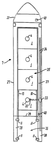
The vessel 7 according to the invention is
illustrated in a top view in Fig. 12. Four wind
turbines 1 have been loaded and placed on the loading
space 25 of the vessel. At the aft end of the vessel,
an unloading position 26 is formed, from which a wind
turbine can be lowered on to the seabed or lifted up
therefrom. As illustrated in the drawing, the vessel
may be a dock ship having a side superstructure 27 on
both sides of the loading deck with a deck part
located higher than the loading deck, or it may be a
vessel of a barge-like nature not having such
continuous higher deck parts in the longitudinal
direction. However, the side superstructures 27
provide the advantage that there are upright sides
that may serve as sideways guides at stowing and
lashing of the wind turbines. Idtoreover, the side
superstructures improve vessel stability in the
heavy-draught condition. The vessel may also be a
semi-submersible with several hulls.
CA 02520219 2005-09-23
WO 2004/087494 PCT/DK2004/000237
At the unloading position 26 the vessel 7 has two
projecting arms 2S, which are extensions of the sides
of the vessel aftwards past a sternpost 29 so that
there is free access downwards to the seabed between
5 the arms. I~t the unloading position of the embodiment
shown, there are four winches 11, each controlling
one of the flexible lines 10, which may, for example,
be a wire line or a chain line. Each winch has a
drive and at least one winch drum with the wire or
10 the chain for the flexible line running up around a
pulley and down to a free end with a fastening member
intended for connection to a fastening member at one
of the lifting points 23 of the wind turbine base 5.
The fastening member may, for example be a shackle
15 mounted at the end of the wire or the chain of the
flexible line. Preferably, the fastening member is of
a type with remote release, for example by actuation
of a hydraulic cylinder. The release may, for
example, be effected by means of a jerk of a
20 releasing line leading from the vessel down to the
hydraulic cylinder at the fastening member or by
means of a wireless signal transmitted to a receiver
on the cylinder. The hydraulic cylinder may, for
example, pull back a pawl engaging with the eye
25 fitting at the lifting point . When the pawl has been
pulled back, the fastening member is released, and
the flexible line 10 may be hoisted. This obviates
the use of a diver to release the lines 10 after
placing the wind turbine on the seabed.
The vessel 7 has ballast means with a pump system
for supply of pressurized liquid, such as seawater.
Such a pump system may be a separate system or be
part of the usual pump systems of the vessel for
supply of flushing water or ballast water for the
needs of the vessel.
The ballast means also comprise hoses for
connection to the pipes of the base at the connection
CA 02520219 2005-09-23
WO 2004/087494 PCT/DK2004/000237
26
place 13. Hoses to be used may depart from a fixed
place on the vessel and have the adequate length to
reach from a wind turbine 1 placed on the loading
space nearest the superstructure 32 of the ship to a
wind turbine placed at the unloading position 26.
alternatively, a hose set may be provided at the
unloading position, and other hose sets at the
loading space. In a preferred embodiment, the hose
sets of the ballast means are mounted on a hose
automat 33 which, as shown in Fig. 12, is
displaceable in the longitudinal direction of the
vessel on a pair of rails 34 on the side
superstructure 27. The hose automat may suitably have
a hydraulically operated lift 35 accommodating at
least one person. The hoses may be carried by the
lift, and when the hoses are not connected to the
pipe of a wind turbine, their connecting parts at the
hose ends may be placed in a holder on the lift.
When a wind turbine is to be moved from the
position of Fig. 2 on the loading space deck to the
floating position shown in Fig. 3, the hose sets are
first connected to the pipes on the wind turbine, and
then ballast is removed from the base. The foremost
lines 10 of the vessel have been connected to the
foremost mounting places 23 on the lower section 5b
of the wind turbine. Then, by operation of the
winches 11, the turbine can be displaced horizontally
to the unloading position 26 shown in Fig. 13, in
which the wind turbine is in a floating position
between the arms 28, and simultaneously the hose
automat 33 is displaced on the rails 34 to follow the
wind turbine.
Then all the flexible lines 10 are connected to
the associated lifting points on the lower section 5b
of the base. The base is still self-floating with all
or most of the upper surface of the lower section 5b
located above the sea surface 9. Then the winches 11
CA 02520219 2005-09-23
WO 2004/087494 PCT/DK2004/000237
27
are actuated to roll up the flexible lines until each
of the lines is subject to a tensile force lifting at
the associated lifting point of the base. The wind
turbine is thus suspended in the flexible lines while
it floats. 2~Taturally, it is also possible to connect
all the flexible lines to the lifting points of the
base before the wind turbine is moored from the
loading space.
In one embodiment, the winches 11 are so-called
constant-tension winches persistently keeping up a
certain tensile force on the line 10 in the actuated
position. This tensile force may suitably be
adjustable for each winch. These winches make it
possible to supply ballast continuously while
increasing the draught of the wind turbine and to
keep up predetermined tensile forces at the lifting
points.
In another embodiment, each winch 11 is controlled
for taking up or paying out depending on whether an
increase or a reduction of the tensile force of the
line 10 is desired.
It is also possible to generate the lifting force
by first taking up the winches 11 in such a way that
the slack of the flexible lines 10 is only just taken
up, that is, that the lifting force is of a small
magnitude when the wind turbine is in its self-
floating position. Then the winches 11 can fix the
flexible lines, and part of the ballast can be
supplied to the ballast tanks 12. In this way, a lift
corresponding to the weight of the ballast supplied
is built up in each of the flexible lines. When, for
example, a third or half the total ballast quantity
has been supplied to the base, the wind turbine may
be lowered some of the way, whereupon further ballast
may be supplied, followed by further lowering and
supply of further ballast, etc., until the full
ballast quantity has been supplied.
CA 02520219 2005-09-23
WO 2004/087494 PCT/DK2004/000237
28
The lift of the individual line corresponds at
most to one fourth of the weight of the wind turbine
when four lines 10 are used. The lift may suitably
correspond to between 5n and 200 of the turbine
weight, and preferably between 10~ and 15~ of the
turbine weight. .
.l~s a result of the upward forces at the lifting
points, the wind turbine is stably suspended by the
vessel when the upper surface of the lower section 5a
is brought down below the sea surface and during the
further lowering as shown in Fig. 14. When the supply
of ballast is completed, the winches 11 are paid out
so that the wind turbine sinks downwards towards the
seabed. When the wind turbine is placed on the seabed
as shown in Fig. 5, the lines are released. Then the
wind turbine can be connected to the grid, and so-
called scour protection be laid out around the lower
part of the base to protect it.
Preferably there is one hose set for each ballast
tank of the base, and in each set there is a hose for
each of the types of pipe leading down to the ballast
tanks 12. One set may thus have a filling hose for
connection to the filling pipe 14, an emptying hose
for connection to the emptying pipe 16 and possibly a
sounding hose for connection to the sounding pipe 15.
The filling hose may be connected to the pump for
supply of pressurized liquid or to the ambient air,
and so can the emptying hose. It is also possible
that the hose set has only one hose connected to the
pump with pressurized liquid and that this hose is
then connected to the filling pipe 14 or the emptying
pipe 16 depending on whether ballast is to be
supplied or removed. The other one of the two pipes
may then merely have its cover dismounted so that it
is open to the ambient air.
The ballast means and the winches 11 can be
controlled .from a control station 40. Typically there
CA 02520219 2005-09-23
WO 2004/087494 PCT/DK2004/000237
29
are two control stations 40, one on the vessel bridge
in the superstructure 32 and one located down at the
unloading position 26. The control station has
control members, such as push buttons, for
controlling the winches 11 and the ballast means.
When the tanks have sounding pipes, the current
sounding height of liquid in the associated tanks can
be shown on the control station by means of a
pneumatic pressure gauge connected t~ the sounding
hose. If desired, it is also possible to expand the
control station with a display of the current tensile
forces in the individual lines 10. This may be
effected by suspending the pulley, around which the
line 10 runs, in a sensor (a weighing cell), which.
measures a value representing the current axial load
on the line 10. Alternatively the winch proper can be
equipped for electronic load sensing.
Measurements of the actual axial loads on the
lines 10 can be used as a supplement to or instead of
sounding pipes. Since it is attempted to obtain.
uniform lifts in the lines 10, the direct tensile
measurement by the sensors can also be used for an
automatic alarm signal at the control station when
the axial force of one of the lines deviates by more
than a predetermined limit value from the axial
forces of the other lines. This may, for example,
give rise to a change of the ballast quantity in the
ballast tank furthest away from the lifting point of
the line. The loads measured are thus parameters of a
semi-automatic control of the ballast means, as a
person actuates the ballast means on the basis of the
information.
The measurements of the axial loads on the lines
10 can also be used for automatic control of the
ballast means and the winches 11, for example on the
basis of a predetermined value for the magnitude of
the aggregate lift in the lines 10 and, for example,
CA 02520219 2005-09-23
WO 2004/087494 PCT/DK2004/000237
a predetermined value for the maximum lowering speed.
When it is desired to move the wind turbine from
the seabed, the lines 10 are lowered to the lower
section 5b of the base, and a diver mounts the
5 fastening means of the lines to the lifting points
23. At the same time, the desired hoses from the
ballast means can be mounted on the pipes at the
connecting place 13 on the wind turbine. Then the
winches 11 are actuated until the desired axial
10 forces in the lines 10 have been established. Then
ballast is emptied out from the tanks 12 , and if the
wind turbine is manufactured with the pipe 31, it is
supplied with pressurized liquid at the same time.
When the wind turbine has been raised to the self-
15 floating position between the arms 28 shown in Fig.
4, the lines 10 may be slacked, and the wind turbine
may be displaced to and placed on the loading space
as shown in Figs. 3 and 2.
Details of the various embodiments can be combined
20 into new embodiments according to the invention, and
variations of the said embodiments may be made; the
unloading position 68 may for example be formed in
the stem of the vessel instead of the stern, or the
unloading position may be sideways on the vessel
25 instead of being located at the end of the vessel. In
connection with a sideways location,. the arms with
the winches 11 may be displaceable in the
longitudinal direction of the vessel so that one and
the same set of arms can be actuated in alignment
30 with each wind turbine. It is also possible to
arrange the winches 11 in other ways than as shown,
for example with a winch at the end of the arm and
two winches mounted on the deck of the vessel.
For use in erecting wind farms located at
extensive ocean areas, such as the Atlantic ~cean or
the Pacific Ocean, the vessel may be provided with
jack-up equipment, for example in the form of four
CA 02520219 2005-09-23
WO 2004/087494 PCT/DK2004/000237
31
legs with associated drives for vertical displacement
of the legs in their longitudinal direction. The legs
are mounted on the vessel hull, such. as with one leg
on each side of the vessel at the front and aft
shoulders. Extensive ocean areas often have a
persistent swell with a large wavelength, also when
the weather is otherwise fine and without any wind.
To counter the inconveniences from the swell, the
vessel may be stabilized in relation to the seabed by
actuation of the jack-up equipment, which can lift
the vessel such a limited distance upwards that the
swell no longer causes the vessel to move. Naturally,
the jack-up equipment can only be actuated during the
periods when lowering or raising of a wind turbine is
carried out at the unloading position, while the
equipment is inactive during the periods when the
vessel has a heavy draught for displacement of a wind
turbine from or to the loading position.
In view of accurate positioning of a wind turbine
in a prepared place of installation on the seabed,
the vessel may be equipped with a dynamic positioning
system controlling the vessel propellers 41 and bow
propellers 42 for maintaining a specific position.
The zero point for the vessel determined in the
positioning system may then be the centre point
between the winches 11 at the unloading position.
When the exact intended position of the place of
installation of the turbine has been recorded in the
system, the vessel is thus controlled so as to
maintain the zero point of the vessel vertically
above the intended position. As an alternative to
such a system, the vessel may be anchored at the
correct position.
In a preferred embodiment of the vessel according
to the invention the vessel is a semi-submersible
barge in which the unloading position is located at
the forward end of the hull. The barge can be a
CA 02520219 2005-09-23
WO 2004/087494 PCT/DK2004/000237
32
traditional tow-barge, but is preferably a push-
barge. At the aft end the barge is provided with a
coupling system for connecting the barge with a push
tug. The coupling system can e.g. be of a type with
one or more toothed vertical rods into which the
tugboat can enter into engagement. The relative
vertical positioning between the tugboat and the
barge can vary in the range of 1 to 15 m depending on
the loading condition of the barge. The engagement of
the tugboat with the vertical rods can be released as
desired. This is an advantage when the barge changes
its deadweight because a wind turbine is loaded or
unloaded. At the forward end the barge is provided
with two protruding arms at the unloading positiom..
At the aft end the barge is equipped with one jack-up
leg at either side of the barge. It is an advantage
to lock the position of the barge in relation to the
seabed before the wind turbine is to be lowered into
place on the seabed. When the two jack-up legs have
been lowered to be in contact with the seabed the
position of the barge is locked in relation to the
precise installation site of the wind turbine and
there is not any real need for a dynamic positioning
system in order to guide the wind turbine into a
precise positioning. The barge can have one or more
bow thrusters in the aft end. Preferably the bow
thrusters are azimuth thrusters of a power of e.g.
1000 kW. The barge can e.g. have a loading space of a
width of slightly over 30 m so that one or more wind
turbines with a base having a width of up to 30 m can
be placed on the loading space. It is of course also
possible to locate the unloading position in the aft
end of the barge.
The vessel can be utilized for sailing wind
turbines from a port area to the offshore wind farm
as described in detail in the above. In this case the
vessel is sailing or, in case the vessel is a barge
CA 02520219 2005-09-23
WO 2004/087494 PCT/DK2004/000237
33
is pushed or towed, between the port area. and the
wind farm in order t~ pick up new wind turbines for
placement on the farm. The vessel or barge can also
be positioned for extended periods on the wind farm
and be utilized to lower wind turbines down to the
seabed from a self-floating state. In the latter case
the wind turbines can be towed from the port area or
manufacturing area out to the wind farm. r~.t the wind
farm each wind turbine is floated into the unloading
position at the vessel, the lines from the vessel are
connected to the lifting points on the wind turbine
base, and ballast is supplied to the wind turbine
base while the wind turbine base is held suspended in
the horizontally distanced flexible lines from the
vessel with at least most of the upper surface of the
wind turbine base located above the sea surface,
whereupon the wind turbine is lowered down into
position on the seabed by paying out the flexible
lines from the winches on the vessel.
The installation of the wind farm can be initiated
by preparing the seabed in the areas 101 where wind
turbines are to be located. The seabed is levelled
and possibly compressed to such firmness that it can
support the wind turbine. Then the electric grid 102
is installed on the sea bottom, and a wind turbine
base carrying a transformer station 103 on top of the
upper part 5b is placed on the farm, and the
transformer station is connected to the electric
grid. Then wind turbines are installed, and as the
wind turbines are placed on the farm they are
connected to the electric grid and begin to produce
electricity.