Note: Descriptions are shown in the official language in which they were submitted.
CA 02520734 2005-09-23
Folding Baby Buggy
s The present invention relates to push chairs or prams for infants, and in
particular foldable push chairs or prams.
The main aspect of the present invention relates to the folding mechanism for
the side frames.
io
The standard folding baby buggy consists of two side frames separated by
cross-bars and having a seat or cot mounted between them. Some push-chairs can
have the two side frames moved together for folding (3-dimensional fold);
others have
the distance between the side frames fixed (2-dimensional fold). The standard
form
is of side frame has a delta-shaped side frame, with a front sloping strut or
bar with a
front wheel at its bottom end and a handle at its top end, a rear sloping bar
with a rear
wheel at its bottom end and hinged at its top end to a point around the middle
of the
front sloping bar, and a base bar, linking the two sloping bars, which is
roughly
horizontal and located toward the bottom end of the rear sloping bar. The base
bar is
2o hinged at about its mid-point.
The side frame can then be folded by bending the base bar at its central
hinge,
with its two halves coming together, and bringing together the rear sloping
bar and the
bottom end of the front sloping bar.
The object of this aspect of the invention is to provide a new side frame
folding
mechanism.
CA 02520734 2005-09-23
According to the invention, there is provided a foldable buggy having two side
frames and a child support means attached to each side frame by a respective
support
member, each side frame having forward strut means, rear strut means and
vertical
strut means, the forward strut means comprising an upper section and a lower
section
s pivotally connected to each other to allow folding and unfolding, the
support member
being slidably mounted on the lower section, and including a strut means
pivotally
attached to the upper section and the support means, such that when the buggy
is
folded from an unfolded state to a folded state, the strut means causes the
support
member to slide down the lower section.
to
A baby buggy embodying the invention will now be described, by way of
example, with reference to the drawings, in which:
Fig. 1 is a diagrammatic side view of the buggy frame in the unfolded
position;
1 s Fig. 2 is a diagrammatic side view of the buggy frame during folding; and
Fig. 3 is a diagrammatic side view of the buggy frame in the folded position.
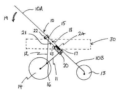
Fig. 1 is a diagrammatic side view of the buggy frame in an unfolded state,
ready for use ("the unfolded position"). The buggy consists of two side
frames, one
2o for each side, which are spaced apart by cross struts. Fig. 1 shows one
side frame; the
opposite side frame is identical. The frame consists of a front sloping bar
10, a rear
sloping bar 11, and a rear vertical bar 12 (the term "vertical" is used merely
for
labeling purposes, as the bar 12 is more nearly vertical than the bars 10 and
11 ). The
front and rear bars 10 and 11 have wheels 13 and 14 attached at their lower
ends. A
2s handle (not shown) is attached at the upper end of the front sloping bar
10; the handle
may consist of a cross-bar between the two side frames. The lower end of the
front
sloping bar 10 is preferably curved, as shown in the figures, to bring the
front wheel
13 backward to some extent.
2
CA 02520734 2005-09-23
The bars 10, 11 and 12 are attached to each other by hinges or pivots 15 - 17.
The front bar 10 is made up of two separate segments, the upper front bar
segment
l0A and the lower front bar segment IOB, which are pivotally connected by a
hinge
18. When the frame is locked in the unfolded position, the hinge 1$ is held in
the
s position shown in Fig. 1, with the bar 10 straight.
A seat or cot can be attached to the buggy frame, using a support member 20.
Alternatively a seat which is convertible to a cot can be attached to the
buggy frame.
A cot 30 is shown, in broken lines, attached to the buggy frame in Fig. 1. The
cot is
to supported on a cross bar mounted between the support members 20 on each
side of
the buggy (the cross bar is not shown in the figures). The cot 30 can be
rigid, if the
buggy is only to fold front to back, or flexible, if the buggy is to fold side
to side also.
The support member 20 is slidably attached to the lower front bar IOB. The
i s support member 20 has a bulbous protrusion which engages with a
corresponding
groove, running along the length of the lower front bar IOB, so that the
support
member 20 can slide along the lower front bar IOB. A rod 21 connects the
support
member 20 to the upper front bar 1 OA; more specifically, the rod 21 is
attached to the
upper front bar l0A at pivot point 22 and to the support member 20 at pivot
point 23.
Referring to Fig. 2, the hinge 18 allows the front bar 10 to fold, in order to
collapse the frame. The upper front bar l0A and lower front bar lOB pivot
about the
hinge 18, the upper front bar l0A pivoting towards the rear wheel 14, as
indicated by
arrow 19. This allows the buggy to be folded into a compact form for storage
(the
2s folded position). As the upper front bar l0A pivots from the unfolded
position to the
folded position, the support member 20 is caused to slide downwards along the
lower
front bar IOB. Similarly, as the buggy is converted from the folded position
to the
unfolded position, the support member 20 is caused to slide upwards along the
lower
front bar IOB. When the buggy is in the unfolded state, the support member 20
abuts
3
CA 02520734 2005-09-23
against a stop 24, which prevents the support member 20 from sliding further
upwards
along the lower front bar IOB. The stop 24 can also incorporate a locking
mechanism, locking the stop 24 and the support member 20 together, to lock the
buggy in the unfolded position.
s
Fig. 3 is a diagrammatic view of the side frame in the folded position. In the
folded position, the dimensions of the frame are such that support member 20
is
located roughly midway between the hinge 18 and the edge of the wheel 13. The
support member 20 is located a distance 1, from the hinge 18 and a distance 12
from the
io outer edge of the wheel 13, where distances l, and 12 are approximately
equal.
The support member 20 is attached to the cot 30 roughly midway between the
front end and the rear end of the cot 30. The length of the base of the cot
30, between
the front and rear ends, is roughly the distance l~ + 1z. The cot 30 is able
to pivot
is about the support members 20, so that the cot base may be horizontal when
the buggy
is in the unfolded position. When the buggy is in the folded position, the cot
can
pivot about support members 20 so that the base of the cot lies parallel with
the lower
front bar IOB.
2o As the buggy frame is folded from the unfolded to the folded state, the
support
member 20 slides along the lower front bar IOB, and the cot 30, which is
attached to
the support member, also moves with the support member, towards the front
wheel
13. When the buggy is in the folded state, as shown in Fig. 3, the base of the
cot 30 is
parallel with the lower front bar lOB and the front and rear ends of the cot
30 are
2s close to the ends of the folded pushchair. The rear end of the cot 30 is
close to the
hinge 18 and the front end of the cot 30 is close to the outer edge of wheel
13.
Therefore, when the buggy is in the folded state the cot does not protrude out
from the
edges of the folded buggy frame. In going from the unfolded position to the
folded
position, the support member 20 slides down the lower front bar lOB until the
support
4
CA 02520734 2005-09-23
member is located half way between the hinge 18 and the outer edge of wheel
13.
Therefore the length of the folded buggy is no longer than the length of the
cot. This
makes the folded buggy easy to store as the different components fold
compactly
together.
If a seat is attached to the buggy frame in place of the cot 30, the length of
the
seat from its top to its bottom should be roughly equal to the distance l, +
12. The
support members 20 should be attached to the seat roughly midway between the
top
and bottom of the seat. Therefore, when the buggy is in the folded state, the
seat will
1 o not protrude from the edges of the folded buggy frame.
Alternatively, the support member can be attached to the cot 30 at a point
other
than the mid-point along the base of the cot. The dimensions of the buggy
frame will
be adjusted accordingly so that when the buggy is in the folded state, the cot
will not
I s protrude from the edges of the folded buggy frame.
The buggy frame of the present invention can be used for a three or four
wheeled buggy. For a four wheeled buggy, the chassis will consist of two side
frames
of Figs. 1 - 3, each having a front and back wheel, the side frame being
separated by
2o cross struts. For a three wheeled buggy, each side frame will have a
respective rear
wheel 14; however, the front wheel 13 will be shared.
s