Note: Descriptions are shown in the official language in which they were submitted.
CA 02520810 2005-09-29
WO 2004/087412 PCT/IB2004/000978
-1-
TITLE: A DURABLE HIGH PERFORMANCE FIBRE CEMENT PRODUCT AND
METHOD OF MANUFACTURE
FIELD OF THE INVENTION
The present invention relates to improved high performance fibre cement
products having
a reduced propensity to carbonation or differential carbonation, and hence
increased durability,
and to methods of making those products.
The invention has been developed primarily for use in relation to external
building
cladding panels and will be described hereinafter with particular reference to
this preferred field.
However, it will be appreciated that the invention is equally applicable to
other fibre reinforced
to cementitious products where improved weathering resistance and durability
are important.
BACKGROUND OF THE INVENTION
The following discussion of the prior art is intended to place the invention
in an
appropriate technical context and facilitate a proper understanding of its
advantages. However,
any discussion of the prior art throughout the specification should in no way
be considered an
admission that such prior art is widely known or forms part of common general
knowledge in the
field.
Fibre reinforced cement (FRC) products are increasingly being used in a
variety of
building applications and in an increasing range of climatically different
situations and
geographical regions. Such products .have gained favour for their inherent
fire, water, pest and
20. mould resistance, as well as their general affordability, which makes them
particularly suitable
for use in meeting commercial as well as residential building codes. Moreover,
FRC products
are easily painted or otherwise coated or laminated with decorative finishes,
such that they can
be used in almost any architectural or interior design.
CONFIRMATION COPY
CA 02520810 2005-09-29
WO 2004/087412 PCT/IB2004/000978
-2-
A growing use of FRC is in external and internal cladding panels which are
manufactured
by applying a customised finish to the front surface of an untreated FRC
board. Such finishes
may include various coatings, vinyl films, laminates or the like depending on
the final
appearance that is required.
Typically, the steps of applying paints or coatings to the surface of FRC
products can be
described as follows:-
~ One or more surfaces are sanded to improve surface smoothness and reduce
thickness
variation;
~ A sealer or "fillcoat" is applied to one or more surfaces.
to ~ The sealer or fillcoat is back sanded to further enhance smoothness. The
steps of sealing
and back sanding may be repeated several times until the surface achieves a
predetermined degree of smoothness and thickness variation.
~ Optionally, a tie coat is applied on top of the sealer to enhance the
adhesion of subsequent
topcoats to the sealer.
~ One or more topcoats are applied to the tie coat and optionally backsanded
and reapplied
mitil the desired finish is obtained.
For high quality finishes, several iterations of sealing, backsanding and
topcoating are
usually required. What is needed is a way to combine one or more of these
steps to reduce the
overall cost of making finished FRC products.
2o Moreover, since exterior paints and topcoats are often formulated from
different
chemistries than sealers, a tie coat or lceycoat must often be used to ensure
the topcoat or paint
continues to adhere to the sealer for as long as possible. Applying and curing
tiecoats add to the
cost of the finished FRC product. What is needed is a way to eliminate the
need for a separate tie
coat.
CA 02520810 2005-09-29
WO 2004/087412 PCT/IB2004/000978
-3-
Although FRC products are known to be more durable than timber and other
conventional building materials, exposure to the elements inevitably causes
chemical changes in
the FRC products over time. This is due in a significant part to the effect of
atmospheric carbon
dioxide on the cementitious product resulting from a process generally
referred to as
carbonation, wherein atmospheric C02 diffuses into the FRC substrate and
reacts with free
calcium hydroxide or calcium silicate hydrates in the presence of water to
form calcium
carbonate, changing the crystalline structure of the FRC substrate. What is
needed is a means of
reducing the ingress of Carbon dioxide and water into the FRC substrate.
While manufacturers of FRC products typically recommend that the rear mounting
to surfaces of such panels be sealed appropriately, this is not always done by
builders, and even
when it is, the FRC manufacturer has no control over the quality of any hidden
face sealing that
may be applied. What is needed is a means of ensuring that FRC products are
adequately sealed
on the back prior to installation.
As a result of the above installation practices, some portions of an FRC
product may
carbonate at different rates depending on the degree of exposure and the
integrity of sealers or
other surface treatments. When different portions of the same FRC product
carbonate at
different rates, internal stresses develop. If these stresses are sufficiently
significant they can
manifest themselves visually in the form of surface cracking of the panels
and/or warping and
the like. What is needed is a means of ensuring carbonation or other types of
degradation occur
2o in a balanced, controlled manner, to reduce internal stresses within the
FRC product.
The prior art discloses the use of various sealers on cementitious materials.
For example,
in EP-A 469 295, WO 96/33143 disclose the use of styrene-acrylate dispersions
or pure acrylate
dispersions to improve the protection of cementitious products from the
efflorescence, a
CA 02520810 2005-09-29
WO 2004/087412 PCT/IB2004/000978
-4-
cosmetic problem in which atmospheric carbon dioxide reacts with calcium
hydroxide that has
leached onto the surface of the cementitious product.
EP-A 355 028 describes a process for preventing efflorescence phenomena on
mineral
substrates by applying, to a mineral substrate, a coating which comprises a
conventional polymer
as binder and an aromatic ketone as photosensitiser. This involves
crosslinking of the surface of
the coating.
US6136383 discloses coatings for mineral mouldings which effectively prevent
efflorescence and at the same time do not disadvantageously change their
strength and their
visual appearance on exposure to moisture. The coating is made from a
radiation-curable
to preparation based on polymers which have ethylenically unsaturated double
bonds applied to the
mineral moulding.
However, each of the preceding references focuses on~reducing efflorescence,
which is a
surface phenomenon, as opposed to carbonation, which occurs internally within
the FRC
substrate. Controlling efflorescence requires a sealer which forms a water
barrier. Controlling
internal carbonation requires a sealer that forms a barrier to both carbon
dioxide and water. In
addition, the carbonation reducing sealer must be compatible with the alkaline
chemistry of
cementitous materials and be durable in the intended environment. An
additional constraint is
that the sealer must, on its own or in combination with other materials,
ensure that decorative
topcoats or other architectural coatings applied over the sealer maintain
their adhesion to the
2o sealer throughout the service life of the topcoat. What is therefore needed
is a sealer that
adequately meets the required performance criteria of
~ Reducing or eliminating internal carbonation and specifically differential
carbonation in
an FRC composite;
~ Resisting alkaline attack and being otherwise compatible with cementitous
materials; and
CA 02520810 2005-09-29
WO 2004/087412 PCT/IB2004/000978
-5-
~ Maintaining topcoat adhesion throughout the service life of the topcoat,
regardless of the
type of topcoat used.
It has been suggested that polymeric films may be effective in this area. For
example,
US20010004821A1 discloses the technique of laminating to a rear surface of FRC
panel a
preformed resin sheet of polyethylene, foamed polyethylene sheet, polyethylene
terephthalate,
vinyl chloride sheet or vinylidene chloride (or combinations thereof) prior to
customisation or
installation. This practice is unlikely to be commercially viable as the
process would be costly,
time consuming and an inefficient use of polymeric materials. Laminated filins
or sheets would
not form an inter-penetrating network into the surface of the FRC product and
therefore be
to susceptible to damage or abrasion from adjacent sheets during transport and
storage. It would
therefore limit the subsequent uses to which the resulting FRC product could
usefully be
employed. What is needed is a more efficient way to provide a carbonation
reducing sealer to
the back of an FRC product.
In the specific example of using prefinished FRC building panels for cladding
commercial buildings, previous practice has been to use sealers as fillcoats
to cover surface
imperfections in FRC composites and to reduce excessive absorption or strike-
in of expensive
decorative topcoats into porous FRC substrates. These sealers were then back-
sanded to provide
a smooth surface for the topcoat or only a relatively thin film thickness. In
either case, such
sealers by themselves did not constitute effective carbonation reducing films
and had to rely
2o upon the presence of a thick topcoat layer to provide carbonation
resistance.. Topcoats have a
limited service life, and 'at the end of that life the carbonation resistance
of the FRC composite
was compromised because the prior art method of appliying the sealer was not
directed towards
maintaining resistance to carbonation independently of the topcoat. What is
needed is a method
of providing ongoing carbonation resistance independently of the topcoats on
FRC composites.
CA 02520810 2005-09-29
WO 2004/087412 PCT/IB2004/000978
-6-
US 6162511 discloses radiation curable coating formulations suitable for FRC
products
but does not disclose a means of determining which of these coatings would be
suitable for
reducing carbonation in FRC. Neither does it disclose methods of using the
coating formulations
described therein to provide sealers that will protect FRC composites from
carbonation
independently of the topcoats.
It is an object of the present invention to provide a high performance fibre
reinforced
cement product and methods of making that product which overcome or ameliorate
one or more
of the foregoing disadvantages of the prior art, or at least provide a useful
alternative.
DISCLOSURE OF THE INVENTION
l0 According to a first aspect of the invention, there is provided an
engineered fibre
reinforced cement product including a first major surface to which a
carbonation reducing sealer
is applied and a second generally opposing major surface to which a
carbonation reducing sealer
is applied, so as to reduce propensity for differential carbonation in the
product.
In the description herein, a sealer will refer to a coating or film of
polymeric, organic or
inorganic composition, that is directly in contact with the FRC substrate and
has the effect of
reducing or eliminating the transport of carbon dioxide and liquid water from
the external
environment into the FRC substrate. To be a functionally effective sealer, the
coating must be
. substantially free of holes, pores, cracks or other defects that allow
relatively rapid ingress of
water or carbon dioxide.
2o As used herein, a topcoat or a paint refers to a coating or film of
polymeric, organic or
inorganic composition that provides for decoration and is applied after or on
top of a sealer.
Topcoats or paints are usually directly exposed to the external environment
and eventually
degrade with time and exposure.
CA 02520810 2005-09-29
WO 2004/087412 PCT/IB2004/000978
Preferably, a carbonation reducing sealer is applied to substantially all
surfaces of the
product. The carbonation reducing sealer applied to at least one of said first
and second major
surfaces is preferably a radiation curable sealer. The sealer is preferably
curable by a form of
radiation selected from the group comprising: W, infrared or near infrared;
RF, microwave;
gamma, and electron beam radiation. In alternative embodiments, however, the
sealer may be
thermally, air or chemically curable.
The sealer applied to at least one of the first and second major surfaces is
preferably
composed substantially of a formulation selected from the group comprising:
acrylics; epoxy
acrylates, and urethane acrylate sealers. The sealer may optionally include an
integral adhesion
1o promoting formulation. It should be appreciated that the sealers applied to
the first and second
major surfaces may be composed of substantially the same formulation, or of
different
formulations.
The radiation curable sealer preferably comprises a prepolymer or binder
polymer or
mixtures thereof. The prepolymer may, for example, comprise one or more
oligomer selected
from ethylenically unsaturated polyesters, ethylenically unsaturated
polyethers, ethylenically
unsaturated polyurethanes, ethylenically unsaturated epoxy, oligo-ester
(meth)acrylates and
ethylenically unsaturated poly(meth)acrylates and modified products thereof.
Typical
prepolymers which may be used are acrylated oligomers selected from
polyurethane, epoxy,
polyesters, polyethers and copolymers and block copolymers thereof.
2o In one preferred embodiment, the sealer applied to at least one of said
first and second
major surfaces is provided with adhesion enhancing means adapted to enhance
bonding of a
subsequently applied topcoat. Alternatively, the sealer maybe covered by a
separate keycoat
adapted to enhance bonding of a topcoat. In some applications, however, it
should be
appreciated that a keycoat is not required.
CA 02520810 2005-09-29
WO 2004/087412 PCT/IB2004/000978
_$_
The sealer applied to each of the major surfaces is preferably at least 15
microns, more
preferably between 15 microns and around ~0 microns, and most preferably
between 15 microns
and around 50 microns in overall thickness. The sealer may be applied in a
single application, or
alternatively in multiple coats or stages. The sealer may also be cured in
multiple stages.
In one preferred embodiment, a keycoat is applied over the sealer on at least
one of the
major surfaces following partial curing and prior to full curing of the
sealer, to enhance bonding
between the sealer and the keycoat. Similarly, a topcoat may be applied over
the. sealer on at
least one of the major surfaces following partial curing and prior to full
curing, to enhance
to bonding between the sealer and the topcoat.
Preferably, the sealer is substantially alkali resistant, is preferably
sufficiently cross-
linked to impede migration of carbon dioxide through the sealer to a
predetermined extent, and is
preferably substantially flexible in the cured state.
Preferably, one or more of the chemical composition of the formulation, the
method of
manufacture, and the physical structure of the cured product, are selected in
conjunction with the
sealer to reduce propensity for differential carbonation in the product.
The formulation has a cement to silica ratio that is preferably between 0.2
and around
1.5, more preferably between 0.3 and around 0.9, more preferably between 0.3
and around 0.5,
more preferably still between 0.36 and around 0.43, and most preferably around
0.39 on a dry
weight basis.
The product is preferably formed to achieve a predetermined porosity and
density during
manufacture. The porosity and density are specifically selected to provide
improved resistance
to carbonation or differential carbonation. The predetermined porosity and
density may be
attained by, for example, by pressing the uncured FRC product in an uncured
state until the
CA 02520810 2005-09-29
WO 2004/087412 PCT/IB2004/000978
-9-
target density and porosity are achieved. Alternatively, the predetermined
porosity and density
may be achieved by applying particle packing theory when selecting the
proportions of the
materials used to make the FRC product. Methods of pressing either by stack
press, embossing
rolls or filter press are well known in the industry.
The product has a porosity that is preferably between 30% and around 60%, and
more
preferably between 35% and around 45%. The product has a relative density that
is preferably
between 0.5 and around 2.0, more preferably between 0.8 and around 1.9, and
more preferably
still between 1.2 and 1.6.
The FRC product is preferably formed using a Hatschek process, but may
alternatively be
1o formed by extrusion, the Mazza technique, manual lay-up, or by other
suitable means.
In the preferred embodiment, the product is a fibre reinforced cement sheet
product
configured for use as an exterior cladding panel. Preferably, the sheet is
substantially
rectangular in shape, and the carbonation reducing sealer is applied to all
six sides.
Desirably, the first major surface of the sheet product is a mounting surface
adapted for
inward orientation toward a substrate and the second major surface of the
sheet product is an
exposed surface adapted for outward orientation. The substrate is .preferably
takes the form of a
building frame.
According to a second aspect, the invention provides a method of manufacturing
a
durable fibre reinforced cement product, said method comprising steps of:
mixing a wet fibre reinforced cement formulation;
forming' from said formulation a green product defining first and second
generally
opposing major surfaces;
curing the green product to form a cured product; and
CA 02520810 2005-09-29
WO 2004/087412 PCT/IB2004/000978
-10-
applying a carbonation reducing sealer to said first and second major
surfaces, so as to
reduce propensity for differential carbonation in the product.
One preferred example of a conventional process for forming a green fibre
cement
product is described in Australian Patent Number 515151, which is incorporated
herein in its
entirety by reference.
Preferably, the carbonation reducing sealer is applied to substantially all
surfaces of the
product. The carbonation reducing sealer is preferably a radiation curable
sealer. More
preferably, the sealer is curable by a form of radiation selected from the
group comprising: UV,
infrared or near infrared; RF, microwave; gamma and electron beam radiation.
Alternatively,
to however, the sealer may be thermally, air or chemically curable.
The FRC curing step is preferably performed using a process selected from the
group
comprising: autoclave, air and steam curing:
Preferably, the method includes the further step of compressing the green
product prior to
curing in a controlled manner such that the cured product exhibits a reduced
carbonation gradient
through its cross-sectional profile. The compression step includes application
of pressure to the
green product to achieve a porosity that is preferably between 30% and around
60%, and more
preferably between 35% and around 45%.
The method in one embodiment preferably includes the further step of applying
a lceycoat
over the sealer following partial curing and prior to full curing, to enhance
bonding between the
2o sealer and the keycoat. In an alternative embodiment, the method preferably
includes the further
step of applying a topcoat over the sealer following partial curing and prior
to full curing, to
enhance bonding between the sealer and the topcoat.
Desirably, the preferred radiation curable sealer comprises a radiation
curable acrylic co-
polymer sealer. More preferably, the acrylic copolymer sealer is a clear epoxy
acrylate sealer.
CA 02520810 2005-09-29
WO 2004/087412 PCT/IB2004/000978
-11-
More preferably, the radiation curable sealer combines the functions of a
carbonation reducing
sealer and a key coat, so as to improve the adhesion of subsequent topcoats.
Further, it should be appreciated that the sealer can be applied during the
FRC
manufacturing process, or alternatively, can be applied shortly before, or
even after the product
is mounted to the substrate. Moreover, the first and second major surfaces can
be sealed
simultaneously or at different times. For example, the first major surface can
be sealed during
the FRC manufacturing process and the second major surface can be sealed in-
situ.
According to a third aspect, the invention provides an engineered fibre
reinforced cement
product including a first major surface with a reduced propensity to
differential carbonation,
to wherein the product has a cement to silica ratio of between 0.29 and around
0.51 and a porosity
of between 25% and around 45%.
Preferably, the product includes a major surface to which a carbonation
reducing sealer is
applied. More preferably, a carbonation reducing sealer is applied to
substantially all surfaces of
the product. In a preferred embodiment, the carbonation reducing sealer
applied to at least one
of the major surfaces of the product is a radiation curable sealer.
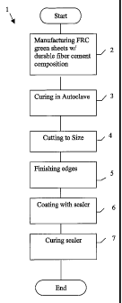
BRIEF DESCRIPTION OF THE DRAWINGS
A preferred form of the invention will now be described, by way of example
only, with
reference to the incorporated tables and accompanying drawing in which:
Figure 1 is a flow chart showing a typical method of malting a high
performance
2o compressed product in accordance with various aspects of the invention.
PREFERRED EMBODIMENTS OF THE INVENTION
The present invention has been developed primarily for use in the manufacture
of high
performance compressed fibre cement sheets specifically configured for use as
external or
CA 02520810 2005-09-29
WO 2004/087412 PCT/IB2004/000978
-12-
internal building cladding and lining panels and will be described hereinafter
with reference to
this application.
Referring to figure l, there is shown a flow chart 1 of a typical
manufacturing process
that is suitable for use with preferred forms of the invention configured for
producing building
cladding panels. Referring to this flow chart, it can be seen that the first
step 2 is the
manufacture of an FRC green sheet, which in preferred forms is made from a
fibre cement
composition that falls generally within the ranges set out in the table below.
Dry Ingredients Acceptable rangePreferred range Optimal formula
(% by dry weight)(% by dry weight) (% by dry weight)
Cement 20 - 3.0% 23.5 - 26.5% 25.0%
Silica 58.5 - 68.5% 62 - 65% 63.5%
Pulp 5.5 -10.5% 7 - 9 % 8.0%
Additives 2 - 5 % 2. 5 - 4. S % 3 .5
Proportions Acceptable rangePreferred range Optimal ratio
.
Cement:Silica .292 -- .513 .362 -- .427 .394
This preferred composition has a reduced cement to silica ratio when compared
with at
least some other prior art formulations, the reduced cement component
contributing to an overall
reduction in carbon dioxide reactions within the finished product. The cement
is typically
ordinary Portland cement type l, and the silica can be any suitable silica
such as 2006 milled
quartz. Examples of suitable siliceous materials include, but are not limited
to, amorphous silica,
diatomaceous earth, rice hull ash, blast furnace slag, granulated slag, steel
slag, mineral oxides,
mineral hydroxides, clays, magnasite or dolomite, polymeric beads, metal
oxides and
hydroxides, or mixtures thereof.
CA 02520810 2005-09-29
WO 2004/087412 PCT/IB2004/000978
-13-
Preferred pulps include various forms of cellulose fibres, such as hammer-
milled Kraft
pulp. However, it will be appreciated that other forms of fibres may be used.
In a particularly
preferred embodiment, the fibre is cellulose wood pulp. Other examples of
suitable fibres are
ceramic fibre, glass fibre, mineral wool, steel fibre, and synthetic polymer
fibres such as
polyamides, polyester, polypropylene, polymethylpentene, polyacrylonitrile,
polyacrylamide,
viscose, nylon, PVC, PVA, rayon, glass ceramic, carbon, or any mixtures
thereof.
It should also be noted that optional additional additives can be incorporated
in to the
composition including viscosity enhancing agents, density modifiers,
dispersing agents, fly ash,
silica fume, geothermal silica, fire retardant, thickeners, pigments,
colorants, plasticisers,
to dispersants, foaming agents, flocculating agents, water- proofing agents,
organic density
modifiers, aluminum powder, kaolin, alumina trihydrate, mica, metakaolin,
calcium carbonate,
wollastonite, polymeric resin emulsions, or mixtures thereof, as required.
In the preferred methods, the sheets are produced using the Hatschek process
in the
conventional manner well known to those skilled in the art. The Hatschek
process uses a
rotating drum sieve arrangement to deposit a plurality of layers of de-watered
slurry onto an
absorbent conveyer until the desired sheet thickness has been achieved.
The preferred green sheet manufacturing process referenced in the flow chart 1
is set to
produce a plurality of green sheets of a particular size which are then
stacked one upon another
and then optionally conveyed to a pressing station. At the pressing station,
the press is
2o programmed to take into account the sheet size and the stack height and the
products are pressed
to achieve a porosity of between 30% and around 60%, and more preferably
between 35% and
around 45%. This pressure is maintained for a predetermined time period as
determined by trial
experiment to achieve the desired outcomes in the final product. After
pressing, the compressed
green products are cured. The curing can be carried out in an autoclave in the
conventional
CA 02520810 2005-09-29
WO 2004/087412 PCT/IB2004/000978
-14-
manner as set out in step 3, or using any number of other conventional
techniques including air
curing.
When curing has been completed, the sheets are typically cut to size '(step 4)
and the
edges are finished (step 5) by passing through a conventional sheet finishing
line where they are
optionally trimmed to size with an edge router to exact dimensions. The
finished FRC sheets are
placed in a stack as they come off the sheet finishing line.
Optionally, a carbonation reducing sealer, which is preferably a radiation
curable epoxy
acrylate sealer, can be applied to the edges of each FRC sheet before it
leaves the sheet finishing
line (step 6). The coating is preferably curable by UV radiation. However,
coatings based on
l0 alternative curing mechanisms such as electron beam, RF, microwave,
infrared and chemical
curing may also be used. Preferred sealer formulations include epoxies,
urethanes, polyesters,
acrylates, and combinations of such formulations.
In some preferred forms of the invention, the finished FRC sheet is then fully
coated on
all six sides (the front face and mounting face being the two major faces, and
the four edges)
with a sealer of the same kind as shown in step 6. This may be done by first
manually roll
coating or spraying the sealer on the edges of the stack of FRC sheets and
then individually roll
coating the sealer on the face and back of an FRC sheet using a conventional
roll coater.
Typically, a stack of 16 sheets is edge coated at one time to maximise
efficiency, but to prevent
drying before the FRC sheets go through the roll coater and are cured.
Preferably, the coating
thickness is in the range of 15 to 50 microns.
Finally, where the applied carbonation reducing sealer is a radiation curable
sealer, the
sealer is then cured with a suitable radiation source appropriate to the
sealer formulation (step 7).
Typical radiation curing systems which may be configured to cure the coatings
used in the
invention may be obtained from Fusion Systems Inc. (910 Clopper Rd.
Gaithersburg, MD),
CA 02520810 2005-09-29
WO 2004/087412 PCT/IB2004/000978
-15-
which provides actinic (UV) curing equipment, Advanced Electron Beam (10 Upton
Drive,
Wilmington, MA) and Energy Sciences, Inc (42 Industrial Way, Wilmington, MA.
01887 USA)
for electron beam curing equipment. Other means of curing radiation curable
coatings are
known, including gamma radiation, near infrared radiation, and microwave
radiation. Curing
may be carried out in atomospheric conditions or under an inert atomosphere,
such as a nitrogen
blanket or C02. It may also be suitable for combine radiation curing with
traditional thermal
curing as is disclosed in US patent application US20030207956A1 and
incorporated herein in its
entirety as a reference.
If the sealer is a UV curable sealer, the sealer may be cured using UV lamps
that provide
1o UV radiation of wavelength from 250 to 400 nm at an intensity of between
200 and 600 watts
per inch, and more preferably between 300 and 600 watts per inch.
If the sealer is cured by electron beam, the electron source will provide an
intensity of
between 50 to 600 KeV,and more preferably between 150 to 300 KeV. Regardless
of the
radiation source, most radiation curable sealers will be adequately cured
after exposure to 80 to
3,000 mJ/cm2 of radiation. Optionally, residual cosolvent or water remaining
in the coating may
be removed by heating the substrate up to a temperature of 80 C via exposure
to IR or NIR
radiation. The carbonation reducing sealers used in the invention may also be
thermally cured
using conventional thermal curing techniques.
The carbonation reducing sealers suitable for this invention are specifically
selected to
2o reduce transport of both carbon dioxide gas and water. These sealers may be
formulated as
solvent based, water based, powder coating or the like. They may be considered
to be 100%
solids or reduced with a suitable solvent or water to achieve a viscosity
suitable for the chosen
application method. Where the carbonation reducing sealer is a radiation
curable sealer, the
sealer may be applied and cured using the techniques described in US patent
3935364,
CA 02520810 2005-09-29
WO 2004/087412 PCT/IB2004/000978
-16-
W00220677A1 and US 6136383, each of which is incorporated herein in their
entirety as
references. Roll coating, curtain coating, spray coating, powder coating and
the like are all
suitable techniques for applying the sealer. In addition, the sealer may be
applied at an elevated
temperature, for example between 30° C and 150 ° C, in order to
enhance curing and adhesion of
the sealer. Alternatively, the substrate itself may be heated to between
30°C and 150°C achieve
the same effect.
Sealer compositions may also comprise, besides the polymeric binder, fillers
and/or
pigments, and also usual auxiliaries such as wetting agents, viscosity
modifiers, dispersants,
defoamers, preservatives and hydrophobisizers, biocides, fibers and other
typical constituents.
to Examples of suitable fillers are aluminosilicates, silicates, alkaline-
earth metal carbonates,
preferably calcium carbonate in the form of calcite or lime, dolomite, and
also aluminum
silicates or magnesium silicates, such as talc. Typical pigments are titanium
dioxide, iron oxides
and barium sulfate. In the case where radiation curable sealers are used,
catalysts or accelerants
such as those disclosed in W00220677A1 may be used to accelerate the curing of
the sealer.
Carbonation reducing sealers which are aqueous dispersions have a solids
content
generally in the range from 20 to around ~0% by weight, and more preferably
from 30 to around
60% by weight, based on the total weight of the conventional coating. Of this,
preferably at least
30% by weight, more preferably at least 50% by weight, and most preferably
from 50 to around
90% by weight, is made up by the polymeric binder. Preferably, not more than
70% by weight,
and more preferably from 10 to around 50% by weight, is made up by pigments
and/or fillers. ~
the case of a clear sealer, the pigment and/or filler content will typically
be less than around
10%. In the case of a keycoat or a combination keycoat/sealer, the filler
content will be between
10% and around 70%, and more preferably between 10% and around 50%.
CA 02520810 2005-09-29
WO 2004/087412 PCT/IB2004/000978
-17-
Carbonation reducing sealers are formulated using a prepolymer or binder
polymer or
mixtures thereof. The prepolymer may, for example, comprise one or more
oligomers selected
from ethylenically unsaturated polyesters, ethylenically unsaturated
polyethers, ethylenically
unsaturated polyurethanes, ethylenically unsaturated epoxy, oligo-ester
(meth)acrylates and
s ethylenically unsaturated poly(meth)acrylates and modified products thereof.
Typical of
prepolymers that may be used are acrylated oligomers selected from
polyurethane, epoxy,
polyesters, polyethers and copolymers and block copolymers thereof.
Examples of preferred polymer binders used in a radiation curable sealer that
are
effective at reducing carbonation are epoxy acrylates and urethane acrylates.
These may be
to obtained from resin formulators and suppliers such as BASF, PPG Industries,
Sartomer, Ballina
Pty Ltd or Akzo Nobel.
Specific sealers that have shown utility as carbonation reducing sealers are
860301-001
UV curable acrylic clear sealer manufactured by Akzo Nobel , VC7 clear and VC9
white UV
curable epoxy acrylate sealers manufactured by Architectural and Industrial
Coatings Pty. Ltd. of
15 Moss Vale Australia. When combined with, for example, 880179-001 key tote
(Akzo Nobel),
having a wet adhesion promoter and a relatively high pigment loading, the
sealer may be coated
with a durable polyurethane or epoxy based decorative topcoat.
Durable adhesion of the topcoat may be achieved by the use of a keycoat
applied to the
surface of the sealer, the lceycoat having a predetermined binder/filler ratio
and optionally having
2o one ore more adhesion promoters. Typical adhesion promoters are: silianes,
silanols, siliconates
or other silicon based adhesion promoters or coupling agents known in the art.
Amine- or
Amino- based adhesion promoters may also be used. These keycoats are used
predominantly to
provide improved adherance to water based coatings such as water based
acrylics, as distinct
CA 02520810 2005-09-29
WO 2004/087412 PCT/IB2004/000978
-18-
from polyurethane and epoxy based topcoats, but any suitable keycoat
formulations may be used
in appropriate circumstances to enhance bonding.
The fillers used for the key coat are selected to achieve a predetermined
degree of surface
roughness in the cured keycoat to enable mechanical bonding. Talc, mica,
carbonates and other
minerals are suitable for this application.
Additionally, a sealer may have an adhesion promoter incorporated directly
into its
formulation, in order to eliminate the need for a key coat. Amine based or
silane based adhesion
promoters have been shown to be effective. The sealer may also have a surface
that is made
rough through the use of specific fillers or by the method of curing.
to It will be appreciated that the invention as described illustrates numerous
ways in which
an FRC product of reduced propensity to carbonation or differential
carbonation and hence
improved durability can be produced. For example, the reduced cement to silica
ratio generally
reduces carbon dioxide reactions within the product, thereby minimising any
differential
carbonation that may apply across various sheet boundaries and through the
final sheet itself.
Similarly, it is believed that controlling permeability and rigidity (as may
be affected by
density), allows carbonation gradients across a sheet to be controlled,
particularly where the
various surfaces may have different levels and types of sealing.
Finally, the factory application of a sealer, and more particularly a
carbonation reducing
sealer such as an acrylic UV curable sealer, to at least the mounting surface
of the panels in a
2o controlled fashion, ensures that there is no risk of the panels being
mounted without adequate
sealing on the mounting surface, thereby again reducing the potential
carbonation differential of
the finished panel once it has been installed. There is the added advantage
with original
manufacturer pre-sealing of increasing the longevity of the base board during
transport and
storage. It also makes it significantly easier for cladding panel finishers
and installers to apply
CA 02520810 2005-09-29
WO 2004/087412 PCT/IB2004/000978
-19-
additional coatings and the like. Certainly, sealing on all six surfaces of a
panel greatly reduces
the chance of severe differential carbonation across a panel, particularly as
can occur when one
or more sides are left untreated.
Each of the above discussed process steps and features separately define
inventive
methods of making improved compressed FRC products. Furthermore, when these
process steps
and features are combined, which can be done in numerous different ways, there
is a synergistic
interaction that enables production of products having vastly superior
performance
characteristics over the prior art.
EXAMPLE
to The following example shows the application of the invention, in one of its
preferred
embodiments, to a compressed FRC sheet manufactured by the applicant and sold
under the
"ExoTec" product name. The general specifications of this product are set out
below, with C:S
denoting the ratio of cement to silica in the formulation.
Porosity v Density v C:S Ratios & Pressing Pressures for Test Products
Product Porosity Density C:S C:S C:S
(vol%) mlcc Possible Preferred O timum
Compressed 30-40% 1.2-1.6 0.29 - 0.34 - 0.46 0.39
- 0.51
Lite (ExoTec) (1.55
Avg)
CA 02520810 2005-09-29
WO 2004/087412 PCT/IB2004/000978
-20-
Formulation Ranges for Porosity and Chemistry Modified Compressed FC
Dry IngredientsAcceptable range'Preferred range Optimal formula
(% b dr wei (% b dr wei ht) (% b dr wei ht)
ht)
Cement 20 - 30% 23.5 - 26.5% 25.0%
Silica 58.5 - 68.5% 62 - 65% 63.5%
Pulp ~ 5.5 -10.5% 7 - 9 % 8.0%
Additives 2 - 5% 2.5 - 4.5% 3.5%
Acceptable rangePreferred range Optimal ratio
Cement:Silica .292 -- .513 .362 -- .427 .394
The product is pressed in the green state using a stack press to form a
product with a
porosity between 30 and 40% and a target density of about 1.55 g/cc. The
product was then
precured for around 80 hours at around 60°C, followed by autoclave
curing at between 120°C
1o and 200°C, for around 24 hours. The product was then sealed in the
manner previously
described, and tested.
TEST RESULTS
Accelerated testing of a conventional high density coated FC composite article
and a
composite FRC article formulated and coated as outlined in this example shows
the significant
performance benefits of the present invention. Under accelerated heat/ rain/
carbonation cycling,
conventional products show a tendency to deform due to the effects of
differential carbonation.
These effects are generally dampened but not eliminated by most traditional
surface coating
treatments that may be applied.
The FRC composite of this invention shows a surprising .and unexpected
improvement in
2o performance. The table below shows deflection results after an accelerated
test involving fixing
CA 02520810 2005-09-29
WO 2004/087412 PCT/IB2004/000978
-21-
a sample of the composite FC product at predetermined points to a support
frame,
preconditioning the composite system in a carbon dioxide rich atmosphere for 8
hours followed
by a predetermined number of cycles of heating to 70C on one surface for 1
hour then surface
wetting at ambient temperatures for 1 hour.
Samples are instrumented to record permanent deflection away from their
initial fixing
position. Deflections are seen as bowing or warping of a product away from a
support frame to
which the sample is fixed. Nil or minimum deflection indicates a sample that
has performed
satisfactorily. Deflections of 50% or more of the composite product's
thickness generally
indicate that the article may not be stable in severe environment
applications.
' Deflection Vs Time in Accelerated Weathering Test
Time Conventional High Density Present Invention 9mm
(mins) 9mm thick thick.
~ Coated FRC deflection mm Deflection (mm)
0 0 0
.5 0.4
40 1.0 0.8
60 1.8 ~ 1.2
100 3.5 2
200 3.8 2
400 6.5 1.75
600 9 1.6
800 9 1.55
1000 11 1.5
1200 11 1.45
1400 10.5 1.4
15 The tables below shows the % carbonation of the hydrated cement phases
present in the
front face, the centre and the rear or mounting face of a fibre cement
composite construction
panel made according to the example, compared to an unsealed standard FRC
formulation.
CA 02520810 2005-09-29
WO 2004/087412 PCT/IB2004/000978
-22-
Exotec FRC Panel Sealed On Front Face
Location Front Centre Rear Deflection(mm
Sealed (Rear) 12.1 14.7 16.8 1.0
Not sealed (Rear)51.2 63.3 61.5 2.0
Conventional FRC Panel Sealed on Front Face
Location front centre rear Deflection(mm)
Sealed (Rear) 12.3 17.9 19.3 2.14
Not sealed 16.8 22.4 37.7 11.0
(Rear)
OB SERVATIONS
Clearly, the test sample manufactured and sEaled in accordance with the
present
1o invention demonstrates superior performance in terms of deformation and
carbonation under the
test conditions, than the corresponding sample according to the prior art.
Thus, it will be appreciated that significant research and development by the
applicant
has resulted in the unexpected realisation of an important mechanism of
degradation and
deformation in fibre reinforced cement products that was not previously
understood, in terms of
differential carbonation. Flowing from this realisation, through the
synergistic interaction of
specifically formulated sealers and coatings, preferably when used in
conjunction with modified
permeability profiles achieved through specifically engineered density
porosity characteristics,
manufacturing techniques and chemical compositions to collectively induce
moderate and
2o relatively.even carbonation gradients in the product, a major limitation of
the prior art is able to
be effectively addressed to a significant degree. Accordingly, the invention
represents a practical
and commercially significant improvement over the prior art.
CA 02520810 2005-09-29
WO 2004/087412 PCT/IB2004/000978
-23-
Finally, it will be appreciated by those skilled in the art that while the
inventive aspects
are particularly suited to FRC compressed sheeting and panels, they are
equally applicable to
other FRC products. Similarly, while the preferred examples illustrate
particular compositions,
pressure ranges and sealants, the invention may be embodied in many other
forms to achieve the
same advantageous results.