Note: Descriptions are shown in the official language in which they were submitted.
CA 02521065 2005-09-30
WO 2004/087325 PCT/IB2004/050386
1
HEAVY PARTtCt~E SEPARAT1~ON
INTR~~~l~Tl~i~:
This invention relates to heavy particle separation. IUlore particularly, this
invention relates to a method and apparatus i.e. a system for heavy particle
separation or recovery from ore, gravel, earth, and the Pike.
f3A~KGR~tJNIg T4 THE fNllENTt~N:
The inventor is aware of a variety of apparatus and processes that have been
used for extracting heavy particles, such as gold, platinum, lead and the
like,
from ore, gravel or sand, earth, including placer ore far example in respect
of
alluvial gold, and the like. Such apparatus and methods suffer from certain
problems including an inability to deal with a broad range of particle sizes
and a
failure to recover fine particles. This reduces the efficiency and hence the
profitability of such recovery systems.
Another disadvantage is that certain recovery systems involve the use of large
quantities of water. Such large quantities of water are not always available
at a
site where, for example, gold-bearing placer ore is found and processed. Even
in lacafities where large quantities of water are available, such usage can
impact
negatively on the environment, and hence large holding ponds or holding tanks
are required.
CA 02521065 2005-09-30
WO 2004/087325 PCT/IB2004/050386
2
Another disadvantage of conventional placer ore recovery systems is that a
surge is created in water flowing through the system with each new load of
gravel that is added to the system. This results in loss of fine gold
particles.
Further disadvantages of for example existing gold recovery systems include an
extended clean-up time and a large volume of concentrate which add
significantly to the cost of operations; the large sire of equipment; high
capital
cast and difficulty of transporting such equipment.
The inventor is also aware of the apparatus and process disclosed in his
United
States Patent No. 5 108 584, which was granted and published on 28 April
199. This patent describes an outer and inner barrel arrangement. The inner
drum has an upper fragmentation section, an intermediate trammel section and
a lower discharge section. A spray of water is directed into the inner barrel.
The ore is separated into large tailings that are discharged from the lower
end of
the inner drum and fine, light tailings from the outer drum. Heavy, fine
portions
of the material are carried by a spiral on the inside surface of the outer
drum
and discharged into the upper end of a sluice box from the upper end of the
outer drum. The sluice box includes the plurality of landings upon which heavy
material, such as gold, collect. The outer drum may be vibrated to assist in
the
recovery process.
CA 02521065 2005-09-30
WO 2004/087325 PCT/IB2004/050386
3
OBJECTS ~F THE fNVENT10N:
An object of the present invention is to overcome, at least partly, the
shortcomings or disadvantages associated with the prior art systems.
Another object: of the present inventifln is to provide an apparatus and
method
which are both novel and include an inventive step.
SlJMMpeIZY ~F THE INVENTC~N:
According to one aspect of the present invention, there is provided a method
of
heavy particle separafian, including a primary separation stage which includes
the steps of dropping. accumulating, concentrating and discharging of heavy
particles and/or a secondary separation stage for concentrating heavy
particles
which includes the steps of infeeding, stilling and retaining such particles.
The method may include a preliminary separation stage.
The preliminary separation stage may include the steps of adding water to the
feed material, scrubbing, size classification and transportation to the
primary
separation stage.
The preliminary separation stage may include a differential transportation
step
designed to separate heavy, medium and light particles before introduction to
the primary separation stage.
CA 02521065 2005-09-30
WO 2004/087325 PCT/IB2004/050386
4
The primary separation stage may include transporting particles including
heavy
particles between the dropping, accumulating and concentrating steps in the
primary separation stage.
Heavy particles may be discharged from the accumulation zone and ccallected
tar
fed to the secondary separation stage.
Particles from the discharge zone may be collected or fed to the secondary
separation stage.
Particles discharged from the discharge zone may be separated into a leading
section, a central section, and a trailing section before being collected or
fed to
the secondary separation stage.
Particles including heavy particles may be transported between the infeeding,
stilling and retaining steps of the secondary separation stage.
According to another aspect of the present invention, there is provided a
heavy
particle separation apparatus, including a tiltable, transverse belt concavefy
shaped in its central area, and including a spiral rib having any suitable
pitch
provided on the belt outer surface, the rib being adapted to urge material
upwardly along the transverse belt, a material feeder means provided above the
CA 02521065 2005-09-30
WO 2004/087325 PCT/IB2004/050386
transverse belt and a water spray system also provided above the conveyor
belt.
!/l~hen used in this specification, the expression 'transverse belt', means a
conveyor belt in which the belt travels in a direction transverse to the
general
flow of material provided thereon hand not in the same direction as is the
case
with conventional conveyor belts.
The apparatus may include a plurality of idler rollers adjustable in a
vertical
direction to provide any desired profile for the transverse belt.
The apparatus may include a classification system to provide the material
feeder means with material sma!!er than about 2.5cm.
The material feeder means may include a feed conveyer belt andlor sloping
chute so that it provides an even differentiated feed of material to the
transverse
belt.
The material feeder means may be provided above the transverse belt operated
conveyor belt and near ane side thereof.
The water spray system may be provided above and near the opposite side of
the transverse belt to the material feeder means.
CA 02521065 2005-09-30
WO 2004/087325 PCT/IB2004/050386
6
The rib may be replaced by a groove having any suitable pitch and/or fibs belt
surface may slave any suitable texture. The rib or groove, as applicable, may
have a suitable varying pitch along its length; and may have a suitable
varying
height rar depth, as applicable, along its length
The apparatus may include a suitable fiailings trough at the lower end of the
transversely operated conveyor bell and a suitable concentrate trough at the
upper end thereof.
The concentrate trough may lead to a secondary separation means comprising
a suitable sluice box to separate fine heavy material.
According to yet another aspect of the present invention, there is provided a
method of separating heavy particles, including the step of using an apparatus
as herein described.
DETAILED DESCRIPTION OF THIINVENTION:
The invention will now be described in greater detail, by way of non-limiting
example, with reference to the following drawings, in which:
Fig. 1 shows a schematic flow diagram of the method of heavy particle
separation, according to one form of the present invention;
CA 02521065 2005-09-30
WO 2004/087325 PCT/IB2004/050386
7
Fig. 2 shows an end view of part of a heavy particle separation apparatus
shown schematically, according to one form of the present invention forming a
primary separation stage;
Fig. 3 shows an upper plan view of the apparatus ofi Fig.1, also shown
schematically;
Fig. 4 shows an end view of another heavy metal recovery apparatus shown
schematically, according to another form of the present invention;
Fig. 5 shows an end view of the apparatus of Fig. 3 with the conveyor belt
having a different concave section, also shown schematically; and
Fig.6 shows a schematic side view of part of an apparatus farming a secondary
separation stage, according to one form of the present invention.
In the drawings, like reference numerals refer to like parts, unless otherwise
indicated.
Referring firstly to Fig. 1, a flow diagram is shown, indicating one form of
the
method of heavy particle separation, according to the invention.
CA 02521065 2005-09-30
WO 2004/087325 PCT/IB2004/050386
8
The method, as shown in Fig. 1, indicates that material containing heavy
particles such as ore, alluvial gravel, or even processed material, is
supplied or
introduced firstly to a preliminary separation stage. P~lthoucdh not shown,
this
stage includes the steps of adding water to the material for scrubbing and
transportation throughout the process. Such scrubbing has the effect of
liberating mineral particleslheavy particles. The preliminary separation stage
also includes the step of sire classification to ensure that ~aversi~e
(undesirable)
material (larger than, for example, 2.5cm) is removed from the process (after
having been scrubbed).
The preliminary separation stage further includes the step of being fed into
or
supplied to the primary separation stage by using a suitably designed conveyor
belt or a conveyor belt and chute system which is tilted and tapered to a
point
along its inner edge which in itself provides a preliminary separation of
light,
medium and heavy particles. The light parkicles are urged to flow along the
inner edge toward the point of the belt or chute whilst the heavy particles
are
urged to move towards and travel along the outer edge and the shorter part of
the belt or chute, thereby achieving a preliminary separation of light, medium
and heavy particfes.
Particles which are separated as described above are then fed to the primary
separation stage which will be described in greater detail hereunder.
CA 02521065 2005-09-30
WO 2004/087325 PCT/IB2004/050386
9
The primary separation stage includes the step of dropping, accumulating, and
concentrating, with each of these steps taking place in a particular zone,
which
wilt also be described mare fully hereunder.
In the dropping zone, dropping of material takes place (from the
aforementioned
chute and for example on to a transverse belt, both of which will be explained
in
greater detail hereunder).
In the dropping zone, medium to heavy and some low density particles will
settle
to the lowest level and will be transported in spiral fashion up to the
concentration zone. In the upper section of the dropping zone, a certain
amount
of recombination of heavier particles with law density particles will take
place.
Medium to low density particles wilt be exposed to turbulent water action or
scouring in spiral fashion whilst some of the ultra fine (water-suspended)
particles will be washed down to the lower section of the drop zone and
transpor#ed to the accumulation zone.
Water-scoured low density particles and ultra-fine (water-suspended) particles
will fend to be washed from the concentration zone toward and into the
dropping
zone by water in a rallinglturbulent fashion.
CA 02521065 2005-09-30
WO 2004/087325 PCT/IB2004/050386
IO
In the accumulation zone which is located downwardly from the dropping zone,
material is introduced by means of scouring from the dropping zone. in this
zone, accumulation takes pleas t~rpicaliy behind a retention lip or rim and
gravity
settlement takes place within a retained mass. (Viedium to high density
particles
are drawn back in spire! fashion to the dropping zone by means of a so-called
transport wedge of material pushed ahead of a spire! rib, for ez;ample.
1n this zone, as in the other zones, water scouring of light and ultra-Fns
material
takes place over the spirally moving rib, i.e. on the transverse belt.
Any material swept or washed over the lower edge of the accumulation zone is
caught in an adjustable (collection) tray from where it may be collected or
fed to
a secondary separation stage for further treatment of ultra-tine particles.
It should be understood that in all zones, the mix or ratio of material
depends on
various operating parameters (which may in turn depend on apparatus settings)
such as inclination of the transverse belt speed, material feed rate, the
spiral
height, water flow, and the like as well as the characteristics of the feed
material, and the like.
Particles that are transported to the concentration zone from the dropping
zone
include particles having a variety of densities but more particularly high,
high
and medium density particles.
CA 02521065 2005-09-30
WO 2004/087325 PCT/IB2004/050386
lI
Essentially gravity sefifilemenfi flakes place wifihin a refiained mass,
particularly as
far as heavy and medium density particles are concerned. However, water
scouring in spiral, turfaulent/ralling fashion takes place in respect of some
of the
low density particles and uifira-fine (Water-suspended) particles are lifted
and
transported back down to the dropping zone. In other words, in the
concentration zone, although fihe primary process is settlement of heavy and
medium density particles, a measure of scouring of low density and fine
fraction
particles flakes place which are returned to the dropping zone.
The general operation of fihis process has the effect that light particles are
moved downwardly to the accumulafiion zone where they are removed whilst
heavier particles are transported upwardly by the transverse belt to the
concentrafiion zone from where they are discharged.
Finally, discharge of high and medium and some law density particles fakes
place afi the upper end of the concentrafiion zone i.e. in the discharge zone.
Material is swept and/or washed into one or more adjusfiable (collection)
trays
from where they are collected or transported to the secondary separation
sfiage.
By using a spiral separation mechanism and optimal wafer flow, it is possible
to
provide an even flow rate of material and to avoid surging of discharge
material.
CA 02521065 2005-09-30
WO 2004/087325 PCT/IB2004/050386
12
Material which is discharged from the discharge zone can be collected
accordingly by the aforementioned adjustable collection trays in three
sections
namely a leading section, a central section, and a trailing sectican, each o~
which
can be collected or fed to and processed by the secondary separation stage, as
shown in F'ig. 1. As with material from the accumulation zone, such material
can be collected, i.e. separated from material to be further processed, i.e.
for
separation in the secondary separation stage.
Depending on certain factors, material may be separated by using the first
separation stage alone, or by using the second separation stage alone, or
these
two stages maybe combined. The secondary separation stage may include the
steps of infeeding, stilling, retention, and collection of concentrate.
The infeeding step may include transporting material introduced into the
collection trays to a stilling plate. Infeeding facilitates layering and its
velocity is
chosen so as to achieve a density separation of particles.
In the stilling step, a suitable stilling plate is provided so that material
is spread
to facilitate layering and even material flow. This leads to layering of
material
densities and flow velocities are used to ensure that high density particles
form
a tower layer with a lower flow velocity whilst tow density particles form an
upper
layer with a higher flow velocity.
CA 02521065 2005-09-30
WO 2004/087325 PCT/IB2004/050386
13
This step requires that stilling time and design is sufficient to ensure that
material and water or other flcaid flow is predominantly laminar {instead of
turbulent) to optimise retaining or retention of high density particles in the
final
phase cal the secondary separation.
The next step is a retaining step and the aforementioned particles are fed
into
the retaining gone where multiple flaw velocities are created. Rolling,
vortex'
flow causes heavy particles to drop into catchment spaces and light particles
are scoured out of such catchment spaces. Consequently gravity settlement of
heavy particles takes place to the lower layers of catchment spaces, At the
same time scouring of the upperllight particles takes place. Retention of
heavy
particles takes place in such catchment spaces which allows for collection and
removal of such particles.
Collection of concentrate may be carried out manually in batch mode or in an
automatic, continuous manner. In this step, catchment spaces may be partially
or fully filled with heavy particles during the aforementioned retaining step,
Catchment spaces are preferably shielded from water flow and withdrawn from
the retaining gone. Gatchment spaces are washed into final concentrate
collection containers and the containers are removed from the secondary
separation stage.
CA 02521065 2005-09-30
WO 2004/087325 PCT/IB2004/050386
14
If will therefore be seen that the invention provides a comprehensive and
thorough separation method for heavy density particles whether large or small
in
sire.
The aforementioned method may for example and preferably be carried out by
means of the apparatus which is described in greater detail hereunder.
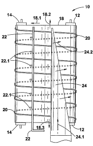
Deferring next to Figs. 2 and 3, reference numeral 10 refers generally to a
heavy particle separation apparatus, shown in schematic form, according to one
form of the invention.
The apparatus 10 includes a head or driven caller 12 and a tail roller 14. The
roller 12 is driven or rotated by a suitable mofior or engine (not shown)
through
an adjustable speed gearbox (also not shown) which enables the head roller to
be driven at a suitable speed, depending on various factors. The rollers 12
and
14 are journalled in suitable bearings (not shown) which in turn are supported
by
a suitable frame (also not shown) that supports the rollers 12 and 14 and
hence
the apparatus 10.
A transverse belt 18 is operatively mounted an the rollers 12 and 14, and
preferably made from a base layer of rubber having a thickness of
approximately 40mm having a top coat of food~grade polyurethane thereon of
about l0mm thickness. The belt 18 has a continuous spiral rib 20, having any
CA 02521065 2005-09-30
WO 2004/087325 PCT/IB2004/050386
suitable pitch provided thereon, which may be made of rubber, pvc, a suitable
polymer, or any other suitable material. In another form of the invention,
fibs belt
18 may be provided without a rib 2a but may instead be provided with a spiral
groove of any suitable pitch. In yet another form of the invention, the
surface of
the bait may be provided with any suitable texture. Although not shown, the
rib
or groove may have a suitable varying pitch slang its length; and the rib 20
or
groove may have a suitable varying height or depth, as applicable, slang ifs
length.
A plurality of idler rollers 16 are provided between the rollers 12 and 14, in
a
concave array to support the belt 18 concavely between the rollers 12 and 14,
as shown in Fig. 2.
When being set up for use, the belt 18 will have its one end i.e. the lower
end as
shown in Fig.3, tilted above the horizontal i.e. upwardly out of the plane of
the
drawing, thereby providing an upper and a tower end. At the lower end, the
first
two spirals of the rib 20 as shown in the drawing may be doubled to about
80mm in height whilst for the rest of the rib 20, the height will be
approximately
40mrn in height.
A water supply pipe 22 is provided along the one side of the belt 18,
including a
plurality of downwardly pointing spray nozzles 22.1 intended to spray water on
CA 02521065 2005-09-30
WO 2004/087325 PCT/IB2004/050386
16
the upper surface of the conveyor belt 18 and thereby to lubricate the surface
of
the belt 18 and to assist in transportation of particles along the belt
surface.
Prav#ded above and along the opposing side of the bait 18 is an are feeder
means in the form of a dawnwardly tilted or s#aped channe#-shaped chute 24
which wil# feed are including heavy particles in the direction shown firstly
by the
arrow 24.1 and then by the arrow 24.2 onto the surface of the belt 18.
The apparatus 10 includes other component parts such as a tailings trough (not
shown} to receive concentrate shown by the arrow 18.3 at the upper end of the
belt 18. The concentrate trough leads to a sluice box (also not shown) far
example, and these parts wil# be discussed hereunder.
In one form of the invention, in order to process large quantities of
material, for
example about 200 tons per hour, the apparatus 10 may have the following
dimensions:
Each of the rollers 12 and 14 may be about 6Qcm in diameter, the overall width
of the belt 18 may be about 5m and the length of the conveyor belt may be
about 7.5m, with the rotational speed of the rollers 12 and 14 being about 40
rpm, The angular inclination of the apparatus 18 may be about 3 to 6 degrees
from the horizontal.
CA 02521065 2005-09-30
WO 2004/087325 PCT/IB2004/050386
17
Referring next to Figs. 4 and 5, idler rollers 16 are shown, essentially to
support
the bait 18 along its upper run or to space the belt from the support frame of
the
apparatus and thereby to prevent damage to the belt 18 along its lower run. in
Fig. 3 the idler r~Ilers 16 are shown in a lower position to provide the belt
18 and
hence the apparatus 10 with a maximum capacity of about ~t~0 tons per hour. It
will be seen that each idler roller 16 is mounted on an adjustable arm 16.1
which may be pivoted and thereby raised to a vertical position (as shown in
Fig.
~.) to provide a different concave profile for the belt 18 i.e. to provide a
smaller
concave profile which can for example deal with a minimum capacity of about
50 tons per hour. The adjustable arms 16.1 are secured by means of suitable
brackets and nuts and bolts (not shown) to the belt support framework as shown
in Figs. 4 and 5.
For this capacity and this belt profile, the water supply pipe 22 may be moved
accordingly to the right hand side of the drawing to ensure that the water
nozzles 22,1 provide water operatively in the concave section of the belt 18,
as
shown in Fig. 5.
Referring lastly to Fig. 6, reference numeral 30 refers generally to part of
the
apparatus constituting the secondary separation stage. An infeeding conveyer
(not spawn) is connected to a stilling plate 32 which in turn is connected to
a
retaininglretention plate 34 which contains a plurality of retaining modules
34.1.
These may be removed far collection of concentrate on a manual batch basis.
Alternatively, and as shown in Fig.6, the retaining modules 34.1 are mounted
CA 02521065 2005-09-30
WO 2004/087325 PCT/IB2004/050386
18
removably on a suitable conveyer means in the form of a caterpillar-type track
36 having a roller-driven system 36.1,
A light particle collecfiion trough 38 is positioned under the track 38 on its
right
hand side and a heavy particle collection trough 40 is positioned under the
track
36 on its left hand side. A shield 42 is provided under the plate 32 to shield
the
modules 34.1 firom water flow. The shield 4~2 is retractable and covers the
modules 34.1 as these are moved away from the material and water flow and
around the track 36. The shield 42 then springs back over the next module
34.1.
in use, the apparatus 10 is operated as set out hereunder.
Material containing heavy particles, or alluvial gravel far example, is first
classified in any manner knawn in the prior art to produce gravel or particles
having a size less than 1 inch or Less than about 2.5cm din other words a
fraction size of minus 1 inch), This material is then fed in the direction
shown by
arrow 24.1 along the chute 24 onto the belt 18 as shown by the arrows 24.2.
The belt 18 is driven by the roller 12 which in turn is rotatabfy driven in
the
direction indicated by arrow 12.1.
Hence the belt 18 is driven in the direction indicated by arrow 18.1 at a
speed
determined by the rotational speed of the rollers 12 and 14 which are rotated
at
about 40 rpm.
CA 02521065 2005-09-30
WO 2004/087325 PCT/IB2004/050386
I9
Water from the nozzles 22.1 on the pipe 22 spray water downwardly onto the
belt 18, and such water will be provided in counter-current fashion both
taecause
it wilt flaw contrary to the direction of the arrow 18.1 due to the concave
shape
of the belt 18 and contrary to the general flow downwardly because the belt 18
is tilted upwardly at the lower end of the drawing in Fig.2
The spiral rib 20 wilt fiend to wave the material upwardly along the slope
i.e.
upwardly along the belt 18 whilst water sprayed from the nozzles 22.1 will
flow
counter-current to such flaw i.e. dawnwardly slang the slope of the belt 18.
This will result in waste moving downwardly i.e. light weight particles of
gravel or
stones moving downwardly in the direction of the arrow 18.2 whilst heavy
concentrate will tend to move upwardly along the belt, urged by the spiral rib
20
and as shown by the arrow 18.3 to exit the belt 18 at its upper end at the
site of
the arrow 18.3 into a concentrate trough (not shown). Light weight particles
of
gravel ar stones will move downwardly in the direction of arrow 18.2 and exit
the
belt 18 at the site of the arrow 18.2 into a tailings trough (also not shown).
Generally speaking, larger nuggets and particles of heavy material, such as
gold, will be trapped ahead of the spiral 20 and such particles, including
fine
particles of material, will be washed by water sprayed onto the belt 18 from
the
CA 02521065 2005-09-30
WO 2004/087325 PCT/IB2004/050386
nozzles 22.1 back into the concave or hollow part of the bait 18 and will move
in
the direction indicated by the arrow 18.2.
Consequently, concentrate, which generally speaking will amount to about 5%
in alluvia( gold mining and upwards of 50% in hard rock ore of the total
volume
of ore fed onto the belt 18, will exit the belt as shown by the arrow 13.3.
When the concentrate leaves the belt as shown by the arrow 13.3, it will drop
into the concentrate trough (not shown) from where it will be fled into a
sluice
box (also not shown) or other suitable means forming a secondary separation
stage, where the heavy metal, for example gold, will be suitably separated
from
the fine material.
Treatment ofi material by the apparatus 10 may provide sufficient separation
of
heavy particles. Alternatively, when used on its own the apparatus 30 may
provide sufficient separation, when used as described above. A further
alternative is to use the apparatus 10 and the apparatus 30 in tandem, as may
be required.
In this manner, the apparatus 10, and the associated method will produce a
high recovery rate of heavy metal, for example gold, typically in excess of
about
98 or even 99%.
CA 02521065 2005-09-30
WO 2004/087325 PCT/IB2004/050386
21
Although not shown, the belt 18 and the rollers 12 and 14, and the frame on
which these are mounted, can conveniently be mounted on a mobile trailer
which can be transported by rail andlor by rcaad. Either such trailer may
conveniently have a suitable jacking means at one end gnat spawn) t~ elevate
car
tilt the conveyor belt suitabiy or alternatively, the framework may have its
own
jacking car tilting means (also not shown) to provide the necessary gradient
for
the apparatus ~g and hence for the belt 'i8.
It will therefore be seen that a novel and inventive method and apparatus i.e.
system is provided for recovering heavy mineral particles, such as gold, from
ore, gravel, or the like, in a simple and an efficient manner which requires
minima! water consumption. Naturally the water used on the belt may be
recycled after settling or filtration, as may be required. Similarly the water
used
in the sluice box may also be recycled, as appropriate.
The method and apparatus of the invention therefore provide a relatively
inexpensive and cast-efficient system for recovering ar separating heavy
minerals from ore, gravel, or the like, relative to existing or prior art
systems.
Although certain embodiments only of the invention have been described andlor
exemplified herein, it will be apparent to any person skilled in the art that
other
possibilities, modifications andlor variations of the invention are possible.
Such
possibilities, modifications and/or variations are therefore to be considered
as
CA 02521065 2005-09-30
WO 2004/087325 PCT/IB2004/050386
22
falling within the spirit and scope of the invention as herein claimed andlor
described or eacerr~pfified.