Note: Descriptions are shown in the official language in which they were submitted.
CA 02521150 2005-09-26
Field of invention
This invention relates to an improved surface covering assembly. More
particularly, the
invention relates to a rollable/foldable surface covering assembly made of a
plurality of
adjacent panels.
Background of the invention
In soccer or any other field sport, the use of synthetic turf has been growing
steadily in recent
years. The advantages of synthetic turfs are numerous. For example, synthetic
turfs do not
need to be cared as much as real grass. Moreover, synthetic turfs are more
durable and in
some case, even removable.
However, synthetic turfs can rarely be used directly on the floor or ground
and they usually
require an underpading of some sort. As it is known in the art, these
underpads can be made of
different resilient materials and can have single or multiple layers. The
synthetic turf and its
attached underpad usually come in the form of large rectangular panels that
are placed, one
adjacent to the next, in a way to cover the desired surface.
There are however some drawbacks with this particular arrangement. First, the
material used
to manufacture the synthetic turf, or any other similar surface, is usually
not the same as the
one or ones used to manufacture the underpad. When there are shifts in
temperature, the
material of the underpad can expand or contract more than the material of the
top surface,
resulting in raised corners or edges or in openings between adjacent panels.
These
unevenness or cracks in the playing surface can create injuries if a player
stumbles upon them.
Another problem arises when a large area of ground or floor has to be covered.
The
installation of each panel can be a long and painstaking process. Each panel
must indeed be
precisely placed and adjusted with its adjacent panels in order to have an
even surface. There
must be no crack or space between contiguous panels. Otherwise, people walking
or playing
on the panels could injure themselves.
Furthermore, when the installation is not meant to be permanent, it means that
each panel may
have to be removed.
CA 02521150 2005-09-26
Another minor problem is an aesthetic one. Indeed, since these panels are
usually rectangular
in shape, when they are installed, they can create a chess-board like pattern.
Even though not
a structural problem, this chess-board like pattern may be unpleasant to the
eye.
One possible way to solve these aforementioned problems would be to use larger
panels. This
would reduce to number of panels required to cover a certain area but would
add a burden on
the persons charged to install these larger but heavier panels. This solution
would also reduce
the chess-board like pattern but only to a certain extent.
Another possible solution to solve these aforementioned problems is to use
rolls. However,
since the underpad material or materials are not as flexible as the turf
material, the underpad
would crack or at least be permanently damaged from the rolling and unrolling
of the
underpad.
There is thus a need for an improved rollable/foldable surface covering
assembly that is easy
to manipulate and faster to install.
There may be also a need for installing such underpads separately from the top
surface or to
install the "underpad" such that it becomes the top surface.
Summary of the Invention
Thus, one embodiment of the surface covering assembly of the present invention
comprises:
~ an elongated sheet made of flexible material;
~ a plurality of adjacent panels, each said panel being fixedly attached to
said sheet, each
pair of adjacent panels forming a linear joint about which one of said panels
may be
folded in relation to the other.
In another embodiment of the invention, the surface covering assembly
comprising a plurality
of adjacent panels, each said panel being resiliently attached to its
neighboring panels and
each pair of said adjacent panels forming a linear joint about which one of
said pair of
adjacent panels may be folded in relation to the other.
2
CA 02521150 2005-09-26
To cover an area larger than the covering surface of a single assembly,
multiple assemblies
can be adjacently disposed to cover the area.
The invention also comprises a method for covering an area having boundaries
with surface
covering assemblies, each said assembly comprising an elongated sheet made of
flexible
material and a plurality of adjacent panels, each said panel being fixedly
attached to said
sheet, each pair of said adjacent panels forming a linear joint about which
one of said pair of
adjacent panels may be folded in relation to the other, each said assembly
being rollable, said
method comprising the steps of:
a) providing an assembly in rolled form;
b) unrolling said assembly on said area;
c) adjusting, if necessary, said assembly to remove gaps between said assembly
and said boundaries;
d) adjusting, if necessary, said assembly to remove gaps between said assembly
and other already installed assemblies;
e) repeating steps a), b), c) and d) until said area is covered.
The features of the present invention which are believed to be novel are set
forth with
particularity in the appended claims.
Brief description of figures
Figure 1 is an isometric view of an improved surface covering assembly in
accordance with
the invention;
Figure 2 is an isometric view of the improved surface covering assembly is its
rolled form;
Figure 3 is a isometric view of another embodiment of the improved surface
covering
assembly;
Figure 4 is a partial isometric view of another embodiment of the improved
surface covering
assembly;
Figure 5 is an isometric view of the embodiment of Fig. 4 wherein one panel
has been folded;
3
CA 02521150 2005-09-26
Figure 6 is an isometric view of the embodiment of Fig. 4 wherein all the
panels have been
folded.
Figure 7 is a top view showing a partial staggered row arrangement of surface
covering
assemblies.
Figure 8 is an underside view of a single assembly of another embodiment of
the present
invention.
Figure 9 is a perspective view of a assembly of the embodiment of Fig. 8.
Figure 10 is a perspective view of the joining panel.
Figure 11 is a top view showing a partial staggered row arrangement of surface
covering
assemblies of the embodiment of Fig. 8.
Detailed description of the preferred embodiments
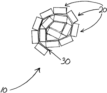
As can be best shown if Fig. 1, the surface covering assembly, generally
indicated as 10, is
mainly composed a plurality of underpad panels 20 attached to a flexible
oversurface 30. The
panels 20 are preferably glued to the oversurface 30 but other means of
attachment can be
envisaged. For example, if both the panels 20 and the oversurface 30 are made
of polymer,
they could heated to be bonded together.
One of the main particularity of a first embodiment of this invention is that
the panels 20 of a
single assembly 10 are not attached to each other otherwise than via the
oversurface 30. This
characteristic allows the assembly 10 to be rolled as shown in Fig. 2. In this
figure, we can
see that the flexible oversurface 30 bends at the junction of two adjacent
panels 20. However,
since adjacent panels 20 are not attached to each other, adjacent panels 20
can separate upon
rolling the assembly 10.
4
CA 02521150 2005-09-26
The person skilled in the art will understand that the length of the assembly
10, and thus the
number of panels 20, are chosen as to best fit the specific use of the
assembly 10. Each panel
can be made more or less wide and the assembly can be made more or less long.
The weight
of the assembly 10 and the ease of manipulation can thus be controlled for
specific
applications.
The skilled addressee will also understand that the oversurface 30 can be any
useful surface
covering such as carpet, synthetic turf, linoleum, rubber sheet, geotextile
fabric, etc. As long
as the oversurface 30 is sufficiently flexible and resilient to be rolled and
unrolled without
being damaged.
Moreover, it is also to be understood that if the application requires it, the
surface covering
assembly can be installed "upside down". Thus, the oversurface 30 would then
be an
"undersurface" 30 and the underpad panels 20 would become "overpad" panels 20.
Such a
configuration would be very useful when the panels 20 are made of a rigid
material such as
wood.
As mentioned before, when the panels 20 of the assembly 10 serve as underpad
for the
assembly, the panels 20 are preferably made of shock absorbent material. In
fact, panels 20
can be made of a plurality of layers (not shown) made of different materials,
each having
different shock absorbing characteristics.
The layer or layers of panels 20 are thus preferably made of expanded or
extruded
polypropylene products, foam products, expanded or extruded
polytetrafluoroethylene,
expanded or extruded polyethylene products, ethylene propylene dime monomer
(EPDM)
products, crumb rubber tire products, plastic products, natural and or
synthetic rubber
products, polyurethane products. Combinations of different materials could
also be used.
The use of other materials, such as wood, could also be envisaged in certain
applications,
especially when the panels 20 are to be placed on top of the flexible surface
30.
In another embodiment of the present invention, shown in Fig. 3, the assembly
100 comprises
a flexible oversurface 130 an a plurality of underpad panels 120. Assembly 100
has the
particularity that some panels 120 are laterally offset with respect to the
longitudinal axis of
5
CA 02521150 2005-09-26
the assembly 100. These offset panels 120 generate openings 140 (the outline
of which is
shown as dotted lines 142) and exterior portions 121. The length of the
exterior portions 121
generally matches the depth of openings 140. Thus, two adjacent assemblies 100
can be
interlocked together by inserting the exterior portions 121 of the first
assembly 100 in the
openings 140 of the second assembly 100. In the preferred embodiment, exterior
portions
121 do not completely fill the opening 140. A small gap is left in order to
accommodate
expansion and contraction of the panels with respect to variation of the
temperature.
When an opening 140 is adjacent to the boundary of the area to be covered,
small inserts (not
shown), preferably made of the same material or materials as the panels and
preferably having
a shape matching the opening's, are inserted in the opening 140. This prevent
the oversurface
130 from sagging under the weight of a person standing over the opening 140.
The person skilled in the art will understand that the pattern of offset
panels 120 shown in Fig.
3 is only an example and that numerous other patterns are possible. Moreover,
the number of
panels shown in Fig. 3 is for illustrative purpose only. The number of panels,
their
dimensions and the dimension of the assembly can be chosen as to best fit the
proposed
application.
To further secure adjacent assemblies 100, VelcroTM patches 122 and 132 can be
attached to
the upper side of exterior portions 121 and the underside of oversurface 130
located in
openings 140. It is to be understood that the type of patches 122 installed on
the upper side of
the exterior portions 121 are complementary to the type of patches 132
installed to the
underside of oversurface 130 located in openings 140.
As for the pattern of the offset panels 120, the pattern of offset panels 120
and openings 140
equipped with VelcroTM patches can be chosen as to best fit a particular
application as long as
the pattern of offset panels 120 equipped with patches and the pattern of
openings 140
equipped with patches complement each other.
Furthermore, other permanent or non-permanent locking means could also be used
instead of
VelcroTM without departing from the scope of the invention.
6
CA 02521150 2005-09-26
In yet another embodiment of the present invention shown in Figs. 4-6, the
surface covering
assembly 200 comprises a plurality of panels 220 alone or to be attached to an
oversurface
(not shown) after the installation of the panels 220. In this embodiment,
adjacent panels 220
are attached together with at least one resilient fastening means 250 such as
an elastic band.
Preferably, a plurality of resilient fastening means are used. In their normal
or "at rest"
position, the resiliency of the fastening means forces neighbouring panels
toward each other,
thus creating adjacent panels without gap between them. However, if someone
wants to roll
or fold assembly 200, the resilient fastener 250 allows for the creation of a
gap between two
adjacent panels 220. Fasteners 250 are preferably embedded into panels 220.
When no
oversurface is pre-attached to the panels, the panels may be folded as shown
in Figs. 5 and 6
or rolled similarly as shown in Fig. 2. Fig. 6 shows an assembly 200 in its
folded
configuration. Although the sides of the panels 220 are shown as straight
lines, when no
oversurface is pre-attached to the panels, the panels 220 may have non-
parallel or non-straight
sides
It is to be understood that Figs. 4 and 5 show the embodiment in its "stretch"
position in order
to show the resilient fasten means. In the normal "at-rest" position, there
are no gaps between
adjacent panels 220.
In Fig. 8, we can see yet another embodiment of the present invention. As best
shown in Figs.
8 and 9, the assembly 300 (shown upside-down) of this embodiment comprises a
plurality of
adjacent underpad panels 320 fixedly attached to an oversurface 330. As for
the first and
second embodiments, the panels 320 are not attached to each other otherwise
than via the
oversurface 330. This embodiment is relatively similar to the first and second
embodiments.
However, the major difference with this embodiment is that the oversurface 330
extends
beyond the area covered by the underpad panels 320. These extensions,
identified with the
numeral 335, allow for fastening means, preferably VelcroTM bands 337, to be
fixedly
attached to the underside of the portion 335 of the oversurface 330 that
extends beyond the
underpad panels 320. The skilled addressee will understand that is it not
mandatory that the
oversurface 330 extends beyond all four sides of the assembly.
When multiple assemblies 300 are needed to cover a given area, adjacent
assemblies 300 are
connected together with the use of joining underpad panels 350. As shown in
Fig. 10, the
7
CA 02521150 2005-09-26
joining underpad panel 350 is a single underpad panel which has a upper side
352 and an
underside 354. The upper side 352 comprises fastening means, preferably
VelcroTM band 357
complementary of the VelcroTM band 337 used on the assemblies 300. Other
fastening means
337 and 357 could be used without departing from the scope of the invention.
The width of the joining panel 350 generally corresponds to twice the width of
the extension
335. Thus, to join two adjacent assemblies 300 together, one or more joining
panels 350 must
be installed between each assembly as shown in Fig. 11. The complementary
VelcroTM bands
337 and 357 of the assemblies 300 and the joining panels 350 generate a strong
connection
between adjacent assemblies 300 and thus prevent any gap to be created between
adjacent
assemblies 300.
It is to be understood that the length of each joining panel 350 may differ to
allow different
combinations of connection. For example, in the preferred embodiment shown in
Fig. 11, we
can see two types of joining panel 350, the "regular" joining panel 350a,
which preferably
extends at least the full length of the oversurface 330, and the "transverse"
joining panel 350b,
which preferably extends the full length of the panels 320. In this preferred
embodiment, the
regular joining panels 350a are preferably installed in an overlapping
arrangement which
increases the overall strength of the total installation. It is however to be
understood that
other arrangements of joining panels 350 and assemblies 300 could be used
without departing
from the scope and spirit of the invention. Moreover, joining panels 350 of
other lengths
could also be envisaged if useful for specific terrains and/or applications.
Moreover, special "half width" joining panels 350 could be used to fill the
gap generated by
the extension 335 when a side of the assembly is adjacent to the physical
boundaries of the
area to be covered. Without those "half-width" joining panels 350, the portion
335 of the
oversurface 330 that extends beyond the panels 320 would sag under the weight
of a player
for example.
Since all these embodiments 10, 100, 200 and 300 may be used outside,
oversurfaces 30, 130
and 330 and panels 20, 120, 220 and 320 may further comprise draining holes
(not shown). In
embodiments 10, 100 and 300, the draining holes in the oversurfaces 30, 130
and 330 are
preferably aligned with the draining holes in the panels 20, 120 and 320
respectively.
8
CA 02521150 2005-09-26
The improved surface covering assemblies described above are given for
illustrative purposes
only. Other embodiments of the improved surface covering assemblies could also
be
envisaged given the need for different surface covering characteristics and
behaviour.
Thus, even though preferred embodiments of the invention have been described
herein, it
should be apparent to those skilled in the art that variations and
modifications are possible
without departing from the spirit of this invention.
9