Note: Descriptions are shown in the official language in which they were submitted.
CA 02521224 2002-03-11
1
A NETWORK AND METHOD FOR SHARING RADIO
ACCESS NODES BETWEEN CORE NETWORKS
This application is a division of Application Ser. No. 2,440,099, filed March
11, 2002.
The present invention relates to cellular radio networks, and in particular to
radio access networks of a cellular radio system.
to Networks of cellular systems are typically divided into a Radio Access
Network RAN and a Core Network CN. Presently the third generation (3G)
radio systems are being standardized. One 3G system will be based on
WCDMA technology, Wide-band Code Division Multiple Access, over the
air interface and thus this technology will be used in the RAN, whereas the
is CN will be similar to the one existing in GSM (Global System for Mobile
communications).
Figure 1 presents a block diagram of the system architecture of a 3G
system. The system comprises the elements shown in Figure 1, i.e. a
2o mobile station MS, the RAN (marked UTRAN, UMTS Terrestrial RAN
where UMTS stands for Universal Mobile Telecommunications System),
and the CN. The mobile station MS is radio connected to at least one base
station BTS which is connected to a radio network controller (RNC) over
the so called lub interface (and two RNCs may be connected with each
25 other over the so called lur interface). Further the RAN is connected to
the
CN over the lu interface. As shown in the figure the RNC is connected to
the MSC (Mobile services Switching Centre) including the VLR (Visitor
Location Register) and to the SGSN (Service GPRS Support Node, where
GPRS is General Packet Radio Service that is standardized in GSM).
CA 02521224 2002-03-11
la
Further the SGSN is connected to the GGSN (Gateway GPRS Support
Node) and the MSC is connected to the GMSC (Gateway MSC). As seen
in the figure at least the MSC, GMSC and SGSN have a connection to the
HLR (Home Location Register) and SCP (Service Control Point). The
connection to other networks go via the GMSC and the GGSN, where
typically circuit switched communication would go via the MSCs (i.e. via the
MSC and GMSC) and packet switched communication would go via the
GSNs (i.e. via the SGSN and GGSN).
CA 02521224 2002-03-11
WO 02/073993 ~ PCT/FI02/00187
2
The radio frequencies that the 3G system (that will be based on WCDMA, Wide-
band Code Division Multiple Access) will use (in communication between the MS
and the BTS) have been agreed by different standardization bodies, and in
several countries licenses to build 3G networks have been sold to operators on
auctions. These licenses have been tremendously expensive. Also building up a
new network additionally requires huge investments to be made on equipment
and there therefore exists questions how the operators will be able to make
profit
and pay off the investments with the 3G system. Moreover, in certain countries
there has been given a requirement of a certain (minimum) coverage area in
order
for the operator to get the 3G network license.
Therefore there is a clear need to seek solutions for saving costs in relation
to
these new networks.
Document WO 01/15471 discloses the use of two parallel core networks for one
BSS (base station sub-system) in order to increase the core network capacity
of
an operator's network by dynamically spreading the toad between the two core
networks. When the mobile terminal registers its presence in the location
area, the
BSS will forward the request dynamically to either of the two core networks
based
on the core network loading. The solution shown does not save costs but rather
adds costs if an operator would use two core networks for each BSS. Further a
drawback of the solution described in the WO document is that it can not be
implemented as such according to the existing mobile network standards, but
would require a change of the present standards.
According to a first aspect of the invention there is provided a method for
radio
communication in a cellular radio network having a radio access network and a
core network, the radio access network comprising at least a radio network
controller and a plurality of base stations, the method comprising
connecting at least two different core networks to one radio access
network, and
sharing at least one base station of the radio access network between
the at least two different core networks by using a first frequency to
establish a
CA 02521224 2002-03-11
3
first cell at the base station for one of the at least two different core
networks and
using a second frequency to establish a second cell at the base station for
another one of the at least two different core networks.
According to a second aspect of the invention there is provided a cellular
radio
network comprising at least two different core networks and one radio access
network connected to each of the at least two core networks, the radio access
network comprises at least a radio network controller and a plurality of base
stations, and each core network comprises network elements, and at least one
base station of the radio access network is configured to be used by each of
the
at least two different core networks, wherein the base station comprises a
transceiver for transceiving at a first frequency to establish a first cell
for one of
the at least two different core networks and for transceiving at a second
frequency
to establish a second cell for another one of the at least two different core
networks.
According to a third aspect of the invention there is provided a radio network
controller comprising:
means for connecting to at least two different core networks,
means for connecting to a plurality of base stations,
allocation means for creating an allocation between traffic to and from
one of the plurality of base stations and the two different core networks,
wherein
the allocation means further comprises a determination of traffic relating to
a
certain first cell established at the base station to correspond to a certain
one of
the at least two core networks to which the traffic is intended, and a
determination
of traffic relating to a certain second cell established at the base station
to
correspond to a certain other one of the at least two core networks in order
to
allocate the traffic from one of the plurality of base stations to either one
of the at
least two core networks based on the cell used at the base station for the
particular traffic.
According to a fourth aspect of the invention there is provided a base station
comprising a transceiver for transceiving at a first frequency to establish a
first
cell, the communication of which is intended for one_ of at least two
different core
CA 02521224 2002-03-11
WO 02/073993 PCT/FI02/00187
4
networks and for transceiving at a second frequency to establish a second
cell,
the communication of which is intended for another one of the at least two
different core networks.
According to a fifth aspect of the invention there is provided a method for
radio
communication in a cellular radio network having a radio access network and a
core network, the method comprising
connecting at least two different core networks to one radio access
network, and
sharing at least one network element of the radio access network
between the at least two different core networks, wherein the at least two
different
core networks belong to different network operators.
According to a sixth aspect of the invention there is provided a cellular
radio
network comprising at least two different core networks and one radio access
network connected to each of the at least two core networks, the radio access
network and each core network comprises network elements, and at least one
network element of the radio access network is configured to be used by each
of
the at least two different care networks, wherein the at least two different
core
networks belong to different network operators.
According to a seventh aspect of the invention there is provided a radio
network
controller comprising:
means for connecting to at least two different core networks, wherein the
at least two different core networks belong to different network operators,
and
means for connecting to a plurality of base stations.
According to a eighth aspect of the invention there is provided a base station
comprising a first cell, the communication of which is Intended for one of at
least
two different core networks that belong to different network operators and a
second cell, the communication of which is intended for another one of the at -
-
least two different core networks
CA 02521224 2002-03-11
WO 02/073993 ~ PCT/FI02/00187
According to a ninth aspect of the invention there is provided a method for
radio
communication in a cellular radio network having a radio access network and a
core network, the radio access network comprising at least a radio network
controller and a plurality of base stations, the method comprising
connecting at least two different core networks to one radio access
network, and
sharing at least one base station of the radio access network between
the at least two different core networks by
establishing a first cell at the base station for one of the at
least two different core networks and using a first code in the first cell
corresponding to the one of the at least two different core networks, and
establishing a second cell at the base station for another
one of the at least two different core networks and using a second code in the
second cell corresponding to the another one of the at least two different
core
networks
According to a tenth aspect of the invention there is provided a cellular
radio
network comprising at least two different core networks and one radio access
network connected to each of the at least two core networks, the radio access
network comprises at least a radio network controller and ~a plurality of base
stations, and each core network comprises network elements, and at least one
base station of the radio access network is configured to be used by each of
the
at least two different core networks, wherein the base station comprises a
transceiver to establish a first cell at the base station for one of the at
least two
different core networks by using a first code in the first cell corresponding
to the
one of the at least two different core networks and to establish a second cell
at
the base station for another one of the at least two different core networks
by
using a second code in the second cell corresponding to the another one of the
at
least two different core networks.
According to an eleventh aspect of the invention there is provided a radio
network
controller comprising:
means for connecting to at least two different core networks,
CA 02521224 2002-03-11
WO 021073993 PCT/FI02100187
6
means for connecting to a plurality of base stations,
allocation means for creating an allocation between traffic to and from one
of the plurality of cells and the two different core networks, wherein the
allocation
means further comprises a determination of a certain first code used in a
first cell
to correspond to a certain one of the at least two core networks to which the
traffic
is intended, and a determination of a certain second code used in a second
cell to
correspond to a certain other one of the at least two core networks in order
to
allocate the traffic from one of the plurality of cells to either one of the
at least two
core networks based on the code used in the cell.
By the definition core network CN there is intended in 3G systems that there
is
both a the packet switched communication elements (such as SGSN) and the
circuit switched communication elements (such as MSC), whereas a MSC
(together with a GMSC) can stand for CS CN (circuit switched core network) and
SGSN (together with a GGSN) can stand for PS CN (packet switched core
network).
In a particular embodiment the two different core networks belong to two
different
operators, whereby the embodiment comprises sharing at feast one element of
the radio access network between at least two different network operators.
However, one single network operator could also have two different core
networks
between which the sharing can be made.
One embodiment comprises sharing at least one of a radio network controller
(RNC) and a base station (BTS) between at least two different core networks
(of
different network operators). In a preferred embodiment both RNCs and BTSs are
shared between at least two different core networks (i.e between two different
network operators): In a network there is a particularly huge number of base
stations when a large geographical area is to be covered, such as a complete
country. Therefore savings can in particular be achieved by sharing base
stations.
Also one embodiment comprises forming with a base station at least two
different
cells, one for each network operator. In a particular embodiment the different
cells
CA 02521224 2002-03-11
WO 02/073993 PCT/FI02/00187
7
are formed by using different frequencies (or frequency bands) for the
different
operators from the same BTS. Moreover in the different cells different
identifications would be used, such as different MNCs (Mobile Network Code).
Therefore the mobile station and the user does not automatically see that
different
operators are not having different base stations but rather share a base
station.
Therefore each operator is able to send out its own identification.
The sharing can also be done by sharing some but not necessarily all sectors
of a
base station. This means that the base station is using narrowband antennae
that
create beams, i.e. sectors to different directions from the base station. For
example a cell may comprise three or six different sectors. Thereby the
sharing
may be done sector-wise and different operators can even create different
coverage in that one operator can use different sectors of a base station than
another. Likewise the sharing may differ geographically in that not
necessarily
each base station of the radio access network is used by each of the sharing
operator but one operator may use one base station alone and another operator
may use another base station alone and thereby different operators may have a
bit different coverage areas if they so like. Typically the network of one
operator
could include several SGSNs and several MSCs.
In a particular embodiment the administration of the sharing is implemented in
a
radio network controller (RNC) by having a routing table where each cell (of
each
base station) is defined and also different core network elements of the at
least
two different core networks are defined. Accordingly an allocation between
each
cell of one and the same network operator and the core network of the same
operator is kept in the routing table of the RNC.
Naturally the sharing of one single radio access network may be equally
implemented between several core networks (and therefore between several
network operators). For example in case of three network operators each base
station would use three different frequencies forming three different cells,
each
belonging to a different core network (to a different operatorj.
CA 02521224 2002-03-11
The present invention can be of help for network operators to quickly build
up a new cellular network covering a certain geographic area. This can be
done by two or more operators building up one single network in co-
operation, which is shared between the operators according to the present
s invention. This also helps in optimizing the use of the capacity of the
network. Namely, in the beginning of a new network the number of
subscribers is typically low and increases over time. By the present
invention subscribers of different operators are able to utilize the same
radio access network and when the number of subscribers increase the
to operators may slowly start building overlapping networks to meet the
demand, and after a while the co-operating operators may have two fully
independent networks (whereby the sharing according to the invention may
be terminated). However, by two or more operators co-operating in the
beginning of the life time of a new network, smaller investments can be
made, but still the operators are able to offer a good geographical
coverage and have sufficient capacity for the subscribers. Thereby the
operators are able to keep the investments on a level where there is
directly a good number of paying customers (subscribers) to generate
income in relation to the investments made.
This is also a benefit to the subscribers as the operators will be able to
keep the service prices on a lower level in that they are not required to
build up a completely independent network in the beginning. No expensive
roaming is therefore needed as the subscribers may move within the
a5 geographical area but during the whole time being served by his/her own
operator. This can be compared to the situation presently in the United
States where certain operators only cover certain States and if the
subscriber moves to a particular State the mobile telephone roams to the
network of another operator and the roaming phone calls are presently very
CA 02521224 2002-03-11
8a
expensive. The present invention will help avoid such problems in new
networks.
According to a still further broad aspect of the present invention there is
provided a method for radio communication in a cellular radio network
having a radio access network (RAN) and a core network (CN). The
method comprises connecting at least two different core networks
(CN1, CN2) to one radio access network (RAN). The method further
comprises sharing at least a radio network controller (RNC) of the radio
to access network (RAN) between the at least two different core networks
(CND, CN2), and creating a routing table in the radio network controller
(RNC). The routing table creates an allocation between traffic at a base
station (BTS) and that core network (CND) of the at least two core networks
(CND, CN2) to which the traffic is intended.
According to a still further broad aspect of the present invention there is
provided a cellular radio network comprising at least two different core
networks (CND, CN2) and one radio access network (RAN) connected to
each of the at least two core networks (CND, CN2), the radio access
ao network (RAN) and each core network (CND, CN2) comprises network
elements (RNC, BTS, MSC, GSN), and at least one network element
(RNC, BTS) of the radio access network (RAN) is configured to be used by
each of the at least two different core networks (CND, CN2), wherein the at
least two different core networks (CND, CN2) belong to different network
as operators, one of said network elements being a radio network controller
(RNC) which comprises a routing table, the routing table creating an
allocation between traffic at a base station (BTS) and core network (CND) of
the at least two core networks (CND, CN2) to which the traffic is intended.
CA 02521224 2002-03-11
8b
According to a still further broad aspect of the present invention there is
provided a radio network controller (RNC) which comprises means for
connecting to at least two different core networks (CND, CN2), wherein the
at least two different core networks (CND, CN2) belong to different network
s operators. The controller also comprises means for connecting to a
plurality of base stations (BTS), and means for creating an allocation
between traffic at the base stations (BTS) and core network (CND) to which
the traffic is intended.
to The invention is described in detail in the following with reference to
enclosed figures, in which
Figure 1 presents the system architecture of a 3G radio system,
CA 02521224 2002-03-11
WO 02/0'73993 PCT/FI02/00187
9
Figure 2 presents the sharing of the a radio access network between two
different operators according to the invention,
Figure 3 presents the sharing of a base station between two core networks,
Figure 4 presents a cell created by a base station,
Figure 5 presents the routing of messages from a core network to a shared base
station,
Figure 6 presents a block diagram of a radio network controller.
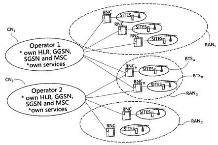
Referring now to Fig. 2 there is disclosed the basic concept of the present
invention. The figure shows a core network CND of a first operator (Operator
1),
which includes network elements such as an own HLR, GGSN, SGSN, MSC and
possible service elements (servers connected to the MSC and or GSN in a
similar
manner as a SM-SC, Short Message Service Centre, is connected to the MSC in
the GSM network). Similarly there is a second core network CN2 of a second
operator (Operator 2), which likewise includes own network elements such as an
own HLR, GGSN, SGSN, MSC and possible service elements. The core networks
CND and CN2 are thus configured and include network elements in the same
manner as known from 3G network plans and as shown in Fig. 1. Similar as
shown in Fig. 1 them are in Fig. 2 radio access networks RANG, RAN2, RANs
connected to the core networks CND, CN2, where RAN1 is connected to CNi in a
known manner and RAN2 is connected to CN2 correspondingly. The sharing
according to the invention is done in the third radio access network RAN3,
where
both core networks CN1 and CN2 are connected thereto.
Thereby, in this example both operators and thus both core networks CN1, CN2
utilise both radio network controllers RNCA and RNCB of RAN3 and also utilize
the
different base stations represented by references BTSA and BTSs. As shown in
Fig.1 there are several base stations connected to each RNC and therefore
references BTSA and BTSB both represent several base stations.
A similar sharing could also be used when the two core networks CND, CN2
belong to one and the same operator.
CA 02521224 2002-03-11
WO 02/073993 . , PCT/FI02/00187
The radio network shown in Fig.2 is thus configured so that operators 1 and 2
can
share RANs (by having shared RNCs and shared BTSs) and each operator have
dedicated own cells through which mobile stations can have access (establish a
connection) to the network. This is shown more closely in Fig. 3. Each cell
has its
own MNC (Mobile Network Code) and MCC (Mobile Country Code) corresponding
to the operator.
The differentiation between the two operators is based on MNC, and as shown in
Fig. 3 MNC1 is used by Operator 1 and MNC2 is used by Operator 2. In practice
this means that a shared RNC (such as RNCA and RNCB) has a preconfigured
routing table which contains the MNC information and by using this information
the messages are routed to appropriate operators core networks CNi and CN2.
The routing is based on a solution where a cell based determination has been
made to corresponding core network CN elements of CND and CN2. The different
cells are formed by using different frequencies for the different operators'
cells
from the same base station BTS. Thereby certain frequencies are determined to
correspond to certain CN elements.
Referring now to Fig. 3 there is disclosed the principle of sharing a base
station.
The two different core network assemblies of each operator represent the
circuit
switched and packet switched portions of the core network. Thereby CS CN of
Operator 1 represents the core network elements of Operator 1 in relation to
circuit switched communications (i.e. the MSCs) and PS CN of Operator 1
represents the core network elements of Operator 1 in relation to packet
switched
communications (i.e. the GSNs). Likewise CS CN of Operator 2 represents the
core network elements of Operator 2 in relation to circuit switched
communications (i.e. the MSCs) and PS CN of Operator 2 represents the core
network elements of Operator 2 in relation to packet switched communications
(i.e. the GSNs). Each CN assembly is connected to the shared RNC. Division
between the CN assemblies is based on LAC (Location Area Code) and RAC
(Routing Area Code) so that the operator can determine in which CN traffic
goes.
Accordingly for circuit switched traffic of operator 1 a first LAC (LAC1) is
used and
for packet switched traffic of operator 1 a first RAC (RAC1) is used.
CA 02521224 2002-03-11
WO 02/073993 PCT/FI02/00~87
11
Correspondingly for circuit switched traffic of operator 2 a second LAC (LAC2)
is
used and for packet switched traffic of operator 1 a second RAC (RAC2) is
used.
The transceiver RX/TX (see Fig. 5) of shared base station (Shared BTS) uses a
first frequency or frequency band (Frequency 1) for establishing a first cell
(of
operator 1 } and uses a different second frequency or frequency band
(Frequency
2) for establishing a second cell (of operator 2).
Fig. 4 shows the concept how typically a cell is formed in WCDMA networks by
using narrowbeam antennae. In the example shown in Fig. 4 the cell is formed
by
three different antennae creating a beam in different directions, each beam
thereby forming an own sector S1, S2 and S3. Typically each sector would use a
different frequency or code to avoid collisions. Another cell may comprise six
different sectors which enable a broader coverage as the beam of an antenna
with a narrower beam typically has a better gain and therefore the beam
reaches
further out. The sharing can be done by sharing the whole cell, i.e. having
two
similar cells that have all sectors S1, S2, S3 of the cell but use different
frequencies (as was described above and shown in Fig. 3), Optionally only some
but not necessarily all sectors of the base station would be used by each of
the
operators. Thereby the sharing may be done sector-wise and different operators
can even create different coverage in that e.g. operator 1 can use sectors S1
and
S2 of the base station and operator 2 may use sectors S2 and S3 of the base
station. Such a sector that is used only by one operator can be created only
on
one frequency, whereas shared sectors must created on several frequencies,
i.e.
on two frequencies if two operators use the shared sector. The different
sectors
can be identified by individual identifications.
Likewise the sharing may differ geographically in that not necessarily each
base
station of the radio access network is used by each of the sharing operator
but
one operator (e.g. Operator 1 in Fig. 2) may use one base station alone (e.g.
BTSA) and another operator (e.g. Operator 2 in Fig. 2) may use another base
station alone (e.g. BTSs) and thereby different operators may have a bit
different
coverage areas geographically if they so like.
CA 02521224 2002-03-11
WO 02/073993' ~ PCT/FI02/00187
1z
Two sharing determinations are included in the shared RNC. For this purpose
the
RNC comprises a preconfigured routing table of operators using same physical
RNC. Each operator has their own cells defined to by the Cell id, the MNC, and
the MCC. Operators are identified with the MNC in the preconfigured routing
table
and the MNC is forwarded from the RRC (Radio Resource Control, which is a
protocol between the mobile station MS and the RAN) to RANAP (Radio Access
Network Application Protocol, which is a protocol over the lu interface) with
the
first Initial Direct Transfer message inside the RNC. Thereby by linking the
information on the RRC and RANAP and MNC a message from a particular base
station can be transferred to the correct CN from RANAP. This allows the
sharing
according to the invention and therefore allows several operators to use one
physical RNC. The protocols RRC and RANAP do not require any changes due to
the invention, but the message routing is done by transferring the MNC and MCC
inside the RNC.
The preconfigured routing table contains also an operator specific list of CN
elements serving an area (a routing area and/or a location area depending of
the
traffic type). Each CN element has its own identification or signaling number
based on which it is identified. With this list it is possible for the RNC to
route the
traffic to the appropriate CN element to serve a particular MS. The selection
is
done when a signalling connection is first established between the MS and the
CN
element. Only one CN element of the same type (Circuit Switched CS or Packet
Switched PS) shall serve the MS at the same time. Accordingly CS and PS
elements are identified separately and the CS and PS traffic is identified
separately by CN domain IDs. When there exists several CNs of the same type
(e.g. several PS CNs and/or several CS CNs as shown in Fig. 3) these are
identified by codes LAC and RAC as was shown and described in connection with
Fig. 3.
Routing of messages between the core networks CNs and the radio access
network RAN is based on MCC (Mobile Country Code), MNC (Mobile Network
Code), LAC (Location Are Code), RAC (Routing Area Code). This is disclosed in
CA 02521224 2002-03-11
WO 02/073993 PCT/FI02/00187
13
more detail in Fig. 5 and Table 1 below which shows an example of a routing
table.
Table 1:
>Operator #1 (MCC + MNC)#1
»CN Domain Identity
»>CS
»»LAC #1 -> CS CN #1
»»LAC #N -> CS CN #n
»>PS
»»RAC #1 -> PS CN #1
»»RAC #N -> PS CN- #n'
>Operator #x (MCC + MNC)#X
»CN Domain Identity
»>CS
»»LAC #9 -> CS CN #9
»»LAC #Z -> CS CN #z
»>PS
»»RAC #6 -~ PS CN #6
»»RAC #Y -> PS CN #y
As shown in Table 1 circuit switched and packet switched traffic is identified
separately by creating an allocation between the circuit switched CN elements
and the LAC which identifies the CS traffic. Likewise an allocation is created
between the packet switched CN elements and the RAC which identifies the PS
traffic. Also above these the CN Domain Identity (CS and PS) is used.to
differentiate between circuit switched and packet switched traffic. Referring
to
Table 1 and Fig. 5 there is created an allocation between the circuit switched
traffic of a particular cell (e.g. Cell #1 ) and the CS CN elements of
Operator #1 by
the definition »»LAC #1 -> CS CN #1. Likewise there is an allocation from cell
#N to the CS CN elements of Operator #1 by the definition »»LAC #N -> CS
CN #n. In a similar manner for packet switched traffic there is an allocation
from
cell #1 to the PS CN elements of Operator #1 by the definition »»RAC #1 -> PS
CN #1. Each data is linked to the operator codes (MCC + MNC)#1. of Operator
#1.
In this manner traffic between cell #1 shown in Fig. 5 to the relevant CN
elements
is routed correctly by the RNC. Thereby each operator #1 to #n (or #X) sends
their
own MNC (MNC#1...MNC#n) to their subscribers. Thereby if a subscriber
CA 02521224 2002-03-11
WO 02!073993 . PCT/FI02/00187
14
activates cell identification on his/her mobile station the cell id (or logo)
of his/her
own operator appears on the display. The MCC is used to route a call to the CN
of
the relevant country (in calls between two different countries). The MCC can
particularly be utilized in cells around country boarders.
Further referring to Fig. 3, there is disclosed a Operating Sub-System element
(OSS) in connection with the RNC. The OSS is also known by the term NMS
(Network Management System), that is used to manage the network by managing
features such as access rights, user ID management, security and monitors
especially the RANs by collecting alarms and key performance indicators
(KPIs) from RAN equipment (from RNCs). The different operators may have
separate OSS equipment (an OSS is typically implemented as one or several
servers) or may share a common OSS (or may agree that the OSS of one of the
operators is used to manage the shared RAN). If one of the operators' OSS is
used then the RAN maintenance is done by that operator's OSS and other
operators can have access to see their own cells (e.g. through a direct
connection
from another operator's OSS to the monitoring OSS).
Operators can agree and co-operate on how to divide costs, cells, transmission
and operationing of a multi-operator RAN. These kind of issues are handled in
the
OSS which includes configurable parameters.
The RAN needs to be synchronized with the CNs. In practice this can be
implemented by agreeing to which of the at least two different CNs that the
shared
RAN is synchronized to. Optionally the two CNs may be mutually clock
synchronized.
Fig. 6 presents a block diagram of a radio network controller RNC. Logically
the
RNC is composed of only two parts, i.e. a broadband switching block 10 arid
controlling entities, i.e. Control Units block 14, Radio Resource Management
block
'15, and Operation and Management block 16 (from where there is a connection
to
the OSS, i.e to the NMS). On the lub interface end the RNC comprises a first
Interface Unit 11, and on the lu interface end the RNC comprises a second
CA 02521224 2002-03-11
WO 02/073993 PCT/FI02/00187
Interface Unit 12. Further there is a third Interface Unit 13 for connections
from
the RNC to other RNCs. The routing table of the RNC is implemented in the
Control Units block 14, which to its hardware implementation is like a
computer.
Therefore as is known a table, such as the one shown in Table 1 can be
implemented as a program in the Control Units block 14, which implements all
RNC control functionalities and the RRC protocol as well as the RANAP protocol
and handles the MNC and MCC, as well as LAC and RAC.
The above has been an introduction of the realization of the invention and its
embodiments using examples. It is self evident to persons skilled in the art
that
the invention is not limited to the details of the above presented examples
and
that the invention can be realized also in other embodiments without deviating
from the characteristics of the invention. The presented embodiments should be
regarded as illustrating but not limiting. Thus the possibilities to realize
and use
the invention are limited only by the enclosed claims. Thus different
embodiments
of the invention specified by the claims, also equivalent embodiments, are
included in the scope of the invention.
The invention provides benefits for network operators in that a good coverage
can
be obtained with low costs (with small investments). Typical areas where to
use
Multiple Operator RAN are rural and suburban areas and other low traffic
coverage needed places e.g. subways and places where it's hard to find spots
to
place several base stations (whereby operators may rather share a base
station).
Cost savings to operators comes from sharing the RAN, i.e. as described here
sharing RNCs and BTSs as well as the OSS. In addition transmission and
transport (i.e. transmission lines such as cables) can be shared and the RNP
(Radio Network Planning) which is done in the OSS.