Note: Descriptions are shown in the official language in which they were submitted.
CA 02521432 2005-10-04
WO 2004/089437 PCT/US2004/010456
GUIDE CATHETER AND METHOD OF MAKING SAME
FIELD OF THE INVENTION
The present invention relates to a guide catheter and a method of
manufacturing the guide catheter. Further, the present invention relates to a
guide catheter configured to be used with expandable devices and devices with
sharp components without damage to the catheter, and a method of
manufacturing such a catheter.
BACKGROUND OF THE INVENTION
Guide catheters are typically used to guide instruments such as balloon
catheters, guidewires or similar devices to specific locations in a human body
to
perform their specific function, such as angioplasty. The inner layer of such
catheters range from .0005 inches to .0015 inches. One problem with current
guide catheters is that they are damaged or rendered inoperable due to
weakness
in the materials as a result of the insertion of current expandable nickel
titanium
devices or devices with sharp components.
There is a need in the art for a guide catheter that has a thin wall thickness
yet has the wall strength to withstand the use of expandable devices made of
such
materials as nickle titanium or devices with sharp components.
BRIEF SUMMARY OF THE INVENTION
The present invention, in one embodiment, is a guide catheter. The
catheter has an inner layer, a support element associated with the inner
layer, and
an outer layer external to the support element. The inner layer has a
thickness of
CA 02521432 2005-10-04
WO 2004/089437 PCT/US2004/010456
from about .0015 inches to about .006 inches. The support element is
configured
to provide shape retention to the guide catheter.
In another embodiment, the present invention is a cutting apparatus. The
cutting apparatus has a rotatable base component, at least two cutting blades
pivotably attached to the base component, and a positioning element configured
to move the cutting blades between a cutting position and a non-cutting
position.
The present invention, in a further embodiment, is a method of attaching a
tip to a catheter. The method includes cutting the catheter with a rotational
cutter, heating material with a heated die, and forming the material into a
tip on
the catheter.
BRIEF DESCRIPTION OF THE DRAWINGS
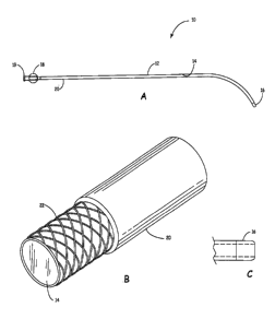
FIG. 1 A is a side view of a guide catheter, according to one embodiment
of the present invention.
FIG. 1 B is a perspective view of a portion of a guide catheter, according
to one embodiment of the present invention.
FIG. 1 C is a side view of a catheter tip, according to one embodiment of
the present invention.
FIG. 2A is a side view of a guide catheter, according to an alternative
embodiment of the present invention.
FIG. 2B is a side view of a catheter tip, according to one embodiment of
the present invention.
FIG. 3A is a cutaway side view of a connection element, according to one
embodiment of the present invention.
-2-
CA 02521432 2005-10-04
WO 2004/089437 PCT/US2004/010456
FIG. 3B is a cutaway side view of a connection element mated with
another connection element, according to one embodiment of the present
invention.
FIG. 3C is a cutaway side view of a connection element, according to an
alternative embodiment of the present invention.
FIG. 3D is a cutaway side view of a connection element mated with
another connection element, according to an alternative embodiment of the
present invention.
FIG. 4 is a flow chart depicting a method of manufacturing a catheter,
according to one embodiment of the present invention.
FIG. 5A is a top view of a cutting apparatus, according to one
embodiment of the present invention.
FIG. 5B is a side view of a cutting apparatus, according to one
embodiment of the present invention.
DETAILED DESCRIPTION
FIG. 1 A depicts a guide catheter 10 according to one embodiment of the
present invention. The guide catheter 10 has an elongated tubular member 12
having an inner layer 14, a catheter tip 16, a connection element 18 including
a
male element 19, and an outer layer 20. According to one embodiment, the guide
catheter 10 is a sheath guide catheter configured to be used in conjunction
with a
dilator guide catheter wherein the dilator is inserted into the sheath, as
will be
described in further detail herein.
-3-
CA 02521432 2005-10-04
WO 2004/089437 PCT/US2004/010456
The inner layer 14 according to one embodiment has a thickness of from
about .0015 inches to about .006 inches. The layer 14 further may be a
slippery
inner surface configured to promote the advancement of any device inserted
into
the guide catheter 10. According to one embodiment, the layer 14 is any
fluoropolymer. For example, according to one embodiment the layer 14 is
comprised of PTFE. Alternatively, the layer 14 is comprised of MFA. In a
further alternative, the inner layer 14 is any similar low-friction material.
The thickness of the inner layer 14 provides a surface that is difficult to
damage by insertion of abrasive objects or devices that apply circumferential
forces. Further, the thickness of the inner layer 14 prevents the guide
catheter 10
from producing unwanted debris and allows for insertion into the body vessels
without creating complications
FIG. 1 B depicts a portion of a guide catheter 10, according to one
embodiment of the present invention. The guide catheter 10 has a support
element 22 integrated into the catheter 10. According to one embodiment, the
support element 22 is braided wire. Alternatively, the support element 22 is a
flexible, kinkless coil. As shown in FIG. 2, the support element 22 is wrapped
around an external portion of the inner layer 14. The thickness of the inner
layer
14 optimizes the ability to include the support element 22. According to one
embodiment, the support element 22 is comprised of tungsten.
The support element 22 is configured to provide a predetermined shape to
the guide catheter 10 that can aide the operator in accessing a desired
location for
use. Further, according to one embodiment, the support element 22 provides a
-4-
CA 02521432 2005-10-04
WO 2004/089437 PCT/US2004/010456
stiffness or rigidity that allows an operator to steer or direct the catheter
10 to
difficult locations that require that the catheter 10 withstand resistance.
For
example, according to one embodiment, the catheter 10 is used to access a
membranous ventricle septal defect ("membranous VSD"). According to an
alternative aspect of the invention, the support element 22 provides a kink
resistance to the catheter 10, such that when the catheter 10 is bent or
deformed,
no kink or permanent deformation results. For example, according to one
embodiment, the support element 22 allows the catheter 10 to be used with a
tortuous device such that the tortuous device can be inserted into or through
the
catheter 10 without resulting in permanent kinks or deformation to the
catheter
I 0.
The outer layer 20 according to one embodiment is configured to be
exterior to the support element 22. Further, the outer layer 20 may conform to
the shape of the support element 22 and, according to one embodiment in which
the support element 22 is braided wire, can be attached to the inner layer 14
in the
gaps (also referred to as "pics") between the braided wires.
The connection element 18 is associated with the tubular member 12 at
the proximal end of the tubular member 12. The connection element 18
according to one embodiment is configured to receive devices. According to one
embodiment, the connection element 18 has an internal diameter ("LD.") that
matches the outer diameter ("O.D.") of the tubular member 12. According to a
further embodiment, the connection element 18 has a male element 19 configured
to be coupleable with a female element on a connection device or loader. In
-5-
CA 02521432 2005-10-04
WO 2004/089437 PCT/US2004/010456
operation, the insertion into the connection element 18 of a connection device
or
loader having an O.D. that is the same as the tubular member 12 allows for
smooth insertion of a device through the connection device or loader and into
the
guide catheter 10.
FIG. 1 C depicts a catheter tip 16, according to one embodiment of the
present invention. The catheter tip 16 is associated with the distal end of
the
guide catheter 10. The tip 16 is configured to prevent portions of the support
element 22 to be exposed at the end of the catheter L0.
FIG. 2A depicts a guide catheter 50, according to an alternative
embodiment of the present invention. The guide catheter 50 has an elongated
tubular member 52 having an inner layer 54, a catheter tip 56, a connection
element 58 including a female element 60 and a male element 61, and an outer
layer 62. According to one embodiment, the guide catheter 50 is a dilator
guide
catheter configured to be used in conjunction with a sheath guide catheter
such
as, for example, guide catheter 10, wherein the dilator is inserted into the
sheath,
as will be described in further detail herein.
The inner layer 54 and outer layer 62, according to one embodiment, have
the same or substantially the same characteristics, composition, and structure
as
the inner layer 14 and outer layer 20, respectively, described herein.
According
to an alternative aspect of the invention, the guide catheter 50 has a support
element (not shown) integrated into the catheter 50, wherein the support
element
has the same or substantially the same characteristics, composition, and
structure
-6-
CA 02521432 2005-10-04
WO 2004/089437 PCT/US2004/010456
as the support element 22 described herein. In a further alternative, the
guide
catheter SO has no support element.
FIG. 2B depicts a catheter tip 56 according to one embodiment of the
present invention. The catheter tip 56 is associated with the distal end of
the
guide catheter 50. The tip 56 is configured to prevent portions of the support
element (not shown) to be exposed at the end of the catheter 50.
FIG. 3A depicts a connection element 58, according to one embodiment
of the present invention. The connection element 58 is associated with the
tubular member 52 at the proximal end of the tubular member 52 as shown in
FIG. 2A. The connection element 58 according to one embodiment is configured
to receive devices and further to connect to devices that the tubular member
52 is
inserted into. According to one embodiment, the connection element 58 has an
internal diameter ("LD.") that matches the outer diameter ("O.D.") of the
tubular
member 52. In operation, the insertion into the connection element 58 of a
connection device or loader having an O.D. that is the same as the tubular
member 52 allows for smooth insertion of a device through the connection
device
or loader and into the guide catheter 50.
According to a further aspect of the invention, the connection element 58
as depicted in FIG. 3A has a male element 61 configured to be coupleable with
a
female element on a connection device or loader that is inserted into the
catheter
50. The male element 61 has protruding elements 61 a that are configured to
contact a female element such that the male 61 and female elements are held in
connection and can be separated only with some force being applied.
CA 02521432 2005-10-04
WO 2004/089437 PCT/US2004/010456
According to another embodiment, the connection element 58 has a
female element 60 as shown in FIG. 3A configured to be coupleable with a male
element on a device into which the catheter 50 is inserted. The female element
60 has inner protruding elements 60a that are configured to contact protruding
elements on a male element (similar to the protruding elements 61 a as shown)
such that the male and female 60 elements are held in connection and can be
separated only with some force being applied, as shown in FIG. 3B.
FIGS. 3C depicts a connection element 58, according to an alternative
embodiment of the present invention. The connection element 58 has a female
element 60 with inner protruding elements 60a and a male element 61 with
protruding elements 61a. FIG. 3D shows the female element 60 of FIG. 3C in
connection with a male element.
FIG. 4 depicts a method of manufacturing a catheter 90, according to one
embodiment of the present invention. According to one embodiment, the method
is a method of manufacturing a sheath guide catheter. Alternatively, the
method
is a method of manufacturing a dilator guide catheter. First, a first layer of
a
fluoropolymer is extruded onto a core rod (block 92). In an alternative aspect
of
the invention, the extruded material can be any known extrudable polymer.
According to one embodiment the core rod is copper. A copper rod can be
stretched after the fluoropolymer has been extruded onto, thereby causing the
diameter of the rod to decrease and simplifying the removal of the rod from
the
formed first layer. Alternatively, the core rod is plastic. According to one
embodiment, this first layer will be the inner layer 14, 54 of the catheter
10, 50.
_g_
CA 02521432 2005-10-04
WO 2004/089437 PCT/US2004/010456
The extruded layer is then etched to create a surface to which other
objects can be attached (block 94). According to one embodiment, the etching
takes place by applying a sodium-based solution to the layer. In an
alternative
aspect of the invention, the extruded layer is not etched. Next, according to
one
embodiment, the support element 22 is applied to the exterior of the layer
(block
96). According to one embodiment, the support element 22 is applied by
braiding the layer with wires. The layer may be braided with from about 8 to
about 32 wires. Alternatively, the support element 22 is a kink-resistant
flexible
coil that is applied to the exterior of the layer. In an alternative
embodiment, no
support element is applied. For example, the manufacture of some dilator guide
catheters does not require application of a support element.
A second layer of plastic is then extruded over the support element 22
(block 98), or if there is no support layer, the second layer is extruded over
the
first layer. According to one embodiment, the plastic is nylon. Alternatively,
the
plastic can be any known plastic for use in medical devices. According to one
embodiment, air pressure is applied during this step to ensure that the second
layer extends through gaps in the support element 22 and attaches to the first
1 aver.
Once the tubular member has been manufactured, additional components
can be added to create the catheter. The connection element 18, 58 is attached
to
an end of the tubular member 12, 52 (block 100). According to one embodiment,
the connection element 18, 58 is attached by molding the connection element
18,
58 onto the end of the tubular member 12, 52. That is, an appropriate mold is
-9-
CA 02521432 2005-10-04
WO 2004/089437 PCT/US2004/010456
placed on the end of the tubular member 12, 52 and hot liquid material is
added
to the mold such that the material forms a connection element 18, 58 that is
molded to the end of the tubular member 12, 52. According to one embodiment,
the molding step is accomplished with a molding machine. Alternatively, the
connection element 18, 58 is attached by any known means for attaching a
component to a catheter.
In one alternative embodiment, the end of the tubular member 12, 52 is
cut with a cutting system (block 102) prior to attachment of a tip 16, 56. For
some embodiments, cutting the end serves to expose an end of the tubular
member and facilitate attachment of a tip. In a further alternative, cutting
the end
of a tubular member having a support member exposes the support member as
well, thereby facilitating complete encapsulation of the support member with
the
tip. According to one embodiment, a mandrel is inserted into the tubular
member
12, 52 prior to the cutting step to facilitate cutting by providing support to
the
tubular member 12, 52 during the process. In a further embodiment, the cutting
system used is a two-blade cutting system described in further detail below.
A tip 16, 56 is then attached to the end of the tubular member 12, 52
opposite the connection element 18, 58 (block 104). According to one
embodiment, the tip is formed from an existing portion of the end of the
tubular
member 12, 52. The end is heated by the application of radio frequency
("R.F.")
energy and then shaped appropriately. Alternatively, the tip is formed by a
molding step in which an appropriate piece of plastic is heated, molded into
the
- 10-
CA 02521432 2005-10-04
WO 2004/089437 PCT/US2004/010456
appropriate shape, and formed onto the catheter using R.F. energy. According
to
one embodiment, the R.F. energy is applied using R.F. dies.
In accordance with one alternative aspect of the present invention, the
resulting catheter 10, 50 is then formed into a desired shape. That is, the
catheter
10, 50 is placed in hot liquid to make the catheter moldable. Alternatively,
the
catheter 10, 50 may be placed on heated platens to make it moldable. The
catheter 10, 50 can then be formed into the desired shape. Subsequently, the
catheter 10, 50 is placed in cold liquid to eliminate its moldability.
FIG. 5A depicts a top view of a cutting system 110, according to one
embodiment of the invention. FIG. 5B depicts a side view of a cutting system
110, according to one embodiment of the invention. According to one
embodiment, the cutting system 110 can be used to cut the tubular member 12,
52
as described above. The cutting system 1 l0 has two blades 1 12 with cutting
edges 116. The blades 112 are pivotably coupled to a base 114 with pivot rods
118 inserted through holes at the non-cutting end of the blades. The cutting
system 1 10 also has tension wires 120 connected at one end to the base 1 14
and
at the other end to the blades 112. The tension wires 120 provide a tension
urging the cutting edges 1 16 of the blades 112 toward the base 114.
Alternatively, the cutting system 110 can have any known component configured
to urge the blades 112 toward the base 1 14 or provide a downward force or
tension on the blades 112 toward the base 1 14.
The system 110 has a positioning element 122 moveably disposed in the
center of the base 1 14 and in contact with both blades 1 12. According to one
CA 02521432 2005-10-04
WO 2004/089437 PCT/US2004/010456
embodiment, the positioning element 122 is a tube element. The tube element
122 is configured to move the blades 112 between a cutting position and a non-
cutting position. That is, when the tube 122 is urged upward (toward the
blades
side of the base 114), the blades 112 are urged upwards and the distance
between
the cutting edges 116 increases. When the upward force on the tube 122 is
removed, the downward force of the tension wires 120 urges the blades 112
downward and the distance between the cutting edges 116 decreases.
Alternatively, the positioning element 122 can be any component configured to
move the blades 112 between a non-cutting position and a cutting position. The
base 114 is configured to rotate or spin around the tube element 122 such that
a
tubular member 12, 52 disposed within the tube element 122 can be cut by the
two blades 112.
According to one embodiment, the two blades 112 cut at two different
locations around the circumference of the tubular member 12, 52, thus applying
an equal amount of pressure around the circumference and cutting in a precise
manner that prevents exposure of any portion of the support element 22 by
forcing the support element 22 inward as it cuts. Alternatively, the cutting
system 110 can have three blades 112. In a further alternative, the cutting
system
1 10 can have 1 to 4 blades 112.
In operation, the cutting system 1 10 can be used to cut a tubular member
10, 50. First, the tube element 122 is urged upward, thereby urging the blades
1 12 upward and increasing the distance between them. When the tube element
122 has urged the blades 1 12 upward such that the distance between the blades
- 12-
CA 02521432 2005-10-04
WO 2004/089437 PCT/US2004/010456
112 is greater than the O.D. of the tubular member 12, 52 to be cut, the
tubular
member 12, 52 is inserted through the tube element 122. Once the tubular
member 12, 52 is properly positioned, the force on the tube element 122 is
released and the blades 112 are urged downward and closer together by the
tension wires 120 until they are in contact with the tubular member 12, 52.
Then
the base 1 14 is caused to rotate or spin such that the blades 112 spin around
the
tubular member 12, 52, thereby cutting the tubular member 12, 52.
While multiple embodiments are disclosed, still other embodiments of the
present invention will become apparent to those skilled in the art from the
following detailed description, which shows and describes illustrative
embodiments of the invention. As will be realized, the invention is capable of
modifications in various obvious aspects, all without departing from the
spirit and
scope of the present invention. Accordingly, the drawings and detailed
description are to be regarded as illustrative in nature and not restrictive.
Although the present invention has been described with reference to
preferred embodiments, persons skilled in the art will recognize that changes
may
be made in form and detail without departing from the spirit and scope of the
invention.
- 13-