Note: Descriptions are shown in the official language in which they were submitted.
CA 02522230 2005-10-04
Docket No. ROPAK-P3163
CONTAINER AND LID WITH MULTIPLE CHAMBERS AND RELATED
METHODS
This invention relates to containers and associated lids, and more
particularly to
containers comprised of multiple chambers or compartments, one of which is in
the
handle, and a lid that can seal the chambers from each other and/or provide
independent
access to those chambers.
Background of the Invention:
The invention is directed to a new apparatus and design and/or configuration,
and
related methods for holding, transporting, storing, stacking, and using
various things.
Containers such as plastic injection-molded buckets, pails, or the like come
in a wide
variety of shapes and sizes. In many applications and methods, the container
and/or
bucket/pail can be used with a cover or other sealing device to help contain
material
within the container. Commonly these containers have covers or lids that,
along with
other aspects of the container/lid combinations, allow the containers to be
nested or
stacked, such as on a pallet.
Most such containers provide a single main storage compartment. Some plastic
bottles (such as for milk, juice, or the like) have "flow-through" handles,
which allow the
fluid to be stored and flow within the handle (but not to be "segregated"
there within the
handle, away from the thing (the liquid) stored in the main storage area of
the
bottle/container).
Certain containers exist with separate "compartments" sealed from each other.
Examples include TV dinners or their equivalent, tool or parts containers with
separate
1
CA 02522230 2012-11-09
_
95176-2
"pockets" in which different screws or bolts or tools are stored, etc. These
typically have one
or more shortcomings that limit their usefulness. For example, and among other
things, many
such containers do not have a handle that functions as a storage compartment,
and do not have
the ability to provide a seal over or between the various compartments, or
permit
separate/discrete access through the lid to the various compartments,
providing some
resealability after the container has initially been opened. Although plastic
bottles exist with
two separate compartments sealed by a single screw-on lid, those containers
are limited in
their use, handling, and other functions (for example, the relatively small
neck and screw-on
lid limit the size and nature of things that might be conveniently packaged
within the
container).
SUMMARY
Embodiments provide an improved container, lid, and combination of the two. A
preferable embodiment is directed to a container having multiple storage
compartments, such
as a main storage body/portion and a hollow handle portion. The compartments
preferably
can be used to store/transport things distinct from each other, but perhaps
related to each
other. Preferably, a single lid covers both or all compartments, and can
provide separate
access to each. In alternative embodiments, separate lids can be provided to
cover each
compartment, and/or no "independent" access may be provided. In alternative
embodiments,
the compartments may be in communication with each other and thus simply
provide
additional storage for the same substance in both portions. The containers
preferably are
nestable with other like containers, and preferably one or more of the
compartments
comprises or is formed within a handle that can be used to manipulate the
container.
In a preferred embodiment, the lid (1) includes tamper-evidencing features,
(2) covers
both the main storage body and the hollow handle, and (3) provides separate
access (via
hinge, removable portion, spout, or otherwise) to each of those areas. Among
other things,
the present invention provides a cover having a built in pour feature (to
permit pouring from a
first or main container chamber) and a separate access mechanism to one or
more further
2
CA 02522230 2012-11-09
95176-2
storage chambers such as the preferred handle storage space, and that
facilitates stacking of
substantially similar containers.
Another embodiment is directed to a lid and container wherein the lid is
configured to
cover the container opening or openings. The lid preferably is characterized
by two or more
openings located on the periphery of said lid, and the container is
characterized by two or
more chambers or compartments.
A further embodiment is directed to a lid for a container, with the lid having
a central
section to cover an opening in the container. The central section has an edge
portion to
contact a rim of the container, and has a center portion that includes a
downwardly oriented
seal structure to sealingly engage a corresponding internal structure on a
container (such as an
internal structure separating two or more chambers of the container from each
other).
Yet another embodiment is directed to the provision of a defined chamber or
storage
compartment in the handle structure of a container. In certain embodiments, at
least one
opening in a mating lid corresponds to the chamber in the container handle, to
permit
independent access to the contents of the handle storage area. Creating one or
more separate
chambers or compartments in the container handle provides great flexibility
for use of the
container, such as facilitating the storage, packing, or inclusion of an
object, material, or
substance which is different from the object, material, or substance placed in
the other
chambers or compartments of the container.
Still another embodiment is directed to the provision of a container formed as
a unitary
body comprised of at least two substantially segregated chambers, in which
said container is
nestable with like containers. Among other things, such nestability can
greatly improve the
economics of storing the containers when they are empty (such as prior to them
being used).
An additional embodiment is directed to a container formed as a unitary body
comprised of at least two substantially segregated chambers, in which one
chamber is
substantially encompassed within a handle portion of said container. Among
other things,
3
CA 02522230 2013-09-25
95176-2
using the handle for storage improves the space efficiency and economics of
the container
during all phases of its manufacture and use.
A further embodiment is directed to a lid and container combination of the
foregoing
character, which further include a detent or otherwise contoured space between
the hinged
openings of the lid, which space corresponds to a detent or contoured bottom
of the container.
Such corresponding structures allow the containers to be stacked or nested
during shipping,
storing, or for packaging.
Another embodiment is directed to a lid and container combination of the
foregoing
character, which further insures the integrity of the final contents of the
container via the
provision of tamper-evidencing structures such as one or more tearstrips. The
tamper-
evidencing structures such as a tearstrip or strips can be of any suitable
configuration and
material, including alternatives that may have an integral or other ring-like
structure for
disengaging the tearstrip(s) from the lid/container assembly, as well as the
potential use of
primary and secondary detent or engagement structures acting between the lid
and container.
In certain embodiments, these structures can be strategically positioned on
the lid and/or
assembly, such as to facilitate the non-hinged portion of the lid remaining
engaged with the
container when the tearstrip(s) have been removed, and to secure the hinged
openings back in
a closed position (engaged with the container opening) when desired.
A further embodiment is directed to the provision of a container and lid
combination
of the foregoing character, in which at least one of the chambers forms a
handle for
manipulating the container, and the container further includes an upper
engaging edge
between the handle chamber and the remainder of the container. The upper
engaging edge
can be configured to sealingly engage with a corresponding seal structure on
the lid, to
thereby seal the handle chamber from communication with the remainder of the
container.
In an aspect, there is provided a container formed as a unitary body comprised
of a
main chamber and a secondary chamber substantially segregated from one
another, wherein
said container is nestable with like containers, wherein said secondary
chamber is unitary with
the main chamber and wherein an upper rim of the container forming a generally
rectangular
4
CA 02522230 2013-09-25
95176-2
periphery around the main chamber and the secondary chamber, wherein the
generally
rectangular periphery includes first, second, third and fourth corner regions,
wherein the
secondary chamber is located at the first corner region and the main chamber
is located at the
second, third and fourth corner regions.
In another aspect, there is provided a container formed as a unitary body
comprised of
a main chamber and a secondary chamber completely segregated from one another,
wherein
said container is nestable with like containers, wherein said secondary
chamber is unitary with
the main chamber and wherein an upper rim of the container forming a generally
rectangular
periphery around the main chamber and the secondary chamber, wherein the
generally
rectangular periphery includes first, second, third and fourth corner regions,
wherein the
secondary chamber is located at the first corner region and the main chamber
is located at the
second, third and fourth corner regions.
Other embodiments and advantages of the invention will be apparent from the
following specification and the accompanying drawings, which are for the
purpose of
illustration only.
5
CA 02522230 2005-10-04
. .
Docket No. ROPAK-P3 163
Brief Description of the Drawings:
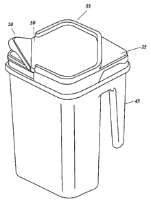
FIG. 1 is a perspective view of one preferred embodiment of the present
invention, including a raised cover portion, a built-in pour feature over a
main container
compartment, a hinged cover portion over a handle compartment, and a tamper
evident
tear strip.
FIG. 2 is a perspective view similar to FIG. 1, and shows the hinged cover
portion
over the handle in an open position, and the tear strip removed.
FIG. 3 is a perspective view similar to FIG. 2, and shows the built-in pour
feature
in an open position.
FIG. 4 is a perspective view similar to FIG. 1, but shows just the container
of
FIGS. 1-3. Preferably, and as further explained below, an internal divider 26
is provided
(preferably integrally formed in the container itself) with an upper edge that
can engage
the associated lid and thereby provide sealing separation between the hollow
handle 45
and the main storage body 65 of the container.
FIG. 5 is a perspective view similar to FIG. 1, but shows two of the
embodiments
of FIGS. 1-4 stacked together. Persons of ordinary skill in the art will
understand that,
among other things, the preferred ridge 55 on the lid enhances the stability
of stacking, by
providing greater engagement/interference between stacked containers (thereby
better
protecting against horizontal shifting between containers, for example).
FIG. 6 is a perspective view of one of the many alternative embodiments of the
invention, showing a recessed cover portion and corresponding recessed
container
bottom.
6
CA 02522230 2005-10-04
Docket No. ROPAK-P3163
FIG. 7 is a perspective view similar to FIG. 6, but shows the hinged handle
cover
portion in an open position, and tear strip removed.
FIG. 8 is a perspective view similar to FIG. 7, but shows the built-in pour
feature
in an open position.
FIG. 9 a perspective view similar to FIG. 6, but shows only the container of
FIGS.
6-8, which container is identical to the container of FIG. 4 but for the
recessed bottom
(shaped to stackingly engage the recessed lid).
FIG. 10 is a perspective view similar to FIG. 1, but shows two container/lid
assemblies of FIGS. 6-9, as they may be stacked together.
FIG. 11 is a perspective view showing still another of the many alternative
embodiments of the invention, including a flat cover with a tamper evident
package
having a tear strip with ring pull feature.
FIG. 12 is a perspective view similar to FIG. 11, but shows the hinged handle
cover in an open position, and its tear strip removed.
FIG. 13 is a perspective view similar to FIG 12, but shows the built-in pour
feature in an open position.
FIG. 14 is similar to FIGS. 12 and 13, but is a sectional view such as might
be
taken along line 14-14 in FIG. 13 if the lid had not yet had its tearstrips
removed and been
opened.
FIG. 15 is similar to FIG. 14, but shows the lid after removal of the
tearstrip
portions near each hinged opening, as the assembly would appear both prior to
the initial
opening of the hinged lid portions and after subsequent closure of those
portions.
7
CA 02522230 2005-10-04
Docket No. ROPAK-P3163
FIG. 16 is similar to FIG. 15, but shows the hinged portions in an open
position.
FIG. 17 is similar to FIG. 14 but shows a container without a "full-height"
interior
wall to divide the handle chamber from the main container chamber.
FIG. 18 is a top view of one embodiment of a container of the invention
(similar
to the container illustrated in FIG. 17) without a lid on it.
FIG. 19A is similar to FIG. 17 with a corner to corner view, but shows a
container
with a "full-height" interior wall to divide the handle chamber from the main
container
chamber.
FIG. 19B is similar to FIG. 17 with a corner to corner view, but shows a
container
with a "full-height" interior wall to divide the handle chamber from the main
container
chamber, and with a "full-height" interior wall to define separate container
chambers.
FIG. 20 is a top view of one embodiment of a container of the invention
(similar
to the container illustrated in FIG. 19A) without a lid on it.
FIG. 21A illustrates another of the many alternative embodiments of the
invention, and is a corner to corner section view similar to FIGS. 17,19A,
showing a
nestable container with multiple container chambers and multiple handle
chambers (one
on the right side and one on the left).
FIG. 21B illustrates another of the many alternative embodiments of the
invention, and is a corner to corner section view similar to FIG. 21A, showing
a nestable
container with multiple "full-height" interior walls to define separate
container chambers
of varied depths and multiple handle chambers (one on the right side and one
on the left).
8
CA 02522230 2005-10-04
Docket No. ROPAK-P3163
FIG. 21C illustrates another of the many alternative embodiments of the
invention, and is a corner to corner section view similar to FIG. 21B, showing
a container
with a single "full-height" interior wall to define separate right and left
side container
chambers, and multiple handle chambers (one on the right side and one on the
left).
FIG. 21D illustrates another of the many alternative embodiments of the
invention, and is a corner to corner section view similar to 21C, showing a
container with
multiple double-walled "full-height" interior container chambers and multiple
handle
chambers (one on the right side and one on the left).
FIG. 22 is a perspective view similar to FIG. 4, but shows the container of
FIG. 17
(without a "full height" internal divider structure).
FIG. 23 is a perspective view of one of the many alternative embodiments of
the
invention, showing a container cover with a snap-on lid or cap molded
integrally with the
cover, showing that snap-on element in an open position.
FIG. 24 is a perspective view the lid of FIG. 23, with the snap-on lid or cap
in an
closed position.
FIG. 25 is a perspective view of the cover of FIGS. 23-24 engaged with the
container of FIG. 22.
FIG. 26 is a perspective view of yet another of the many alternative
embodiments
of a snap-on lid or cap which can be molded separately and affixed in a
suitable manner
to the container cover.
FIG. 27 is a perspective view of the lid or cap of FIG. 26, which has been
affixed
to the container cover, and is in a closed position.
9
CA 02522230 2005-10-04
Docket No. ROPAK-P3163
FIG. 28 is a perspective view of the lid or cap of FIG. 26, which has been
affixed
to the container cover, and is in an open position.
FIG. 29 is a perspective view of still another of the many alternative
embodiments
of the invention, showing a container and lid assembly with yet another of the
many
alternative access elements or structures that can provide access to the
contents of the
container, as a tearstrip opening included in the lid in a downwardly
depending flange
near one of the corners (but which could be included at multiple corners, in
combination
with other cap or tearstrip openings, etc.).
FIG. 30 is a partial perspective view of the "tearstrip" lid corner of FIG.
29.
FIG. 31 is a perspective view similar to FIG. 30, showing the tearstrip in an
open
or partially removed position (other embodiments could include hinging the
tearstrip in
approximately the position shown here).
FIG. 32 is a perspective view similar to FIG. 31, but showing the lid with the
tearstrip completely removed.
Description of Preferred Embodiment:
Broadly, the present invention is directed to a container and lid which
provide
separate compartments within a single container to facilitate, for example,
transportation,
storage, handling, etc. of products that may be related to each other.
The various components of the invention can be fabricated in any suitable
manner
and from any suitable material. Preferably, to provide the container and lid
in a relatively
inexpensive economic and useful manner and form having desirable sealing
discussed
CA 02522230 2005-10-04
Docket No. ROPAK-P3163
herein, the container and lid can be injection molded or otherwise formed from
one or
more suitable materials. By way of example and not by way of limitation, these
could
include plastic, vinyl, or similar material, metal, injection or blow-molded
materials, and
others.
As explained further below, FIGS. 1-5 illustrate one of the many embodiments
of
the invention, one having a main storage body/portion and a preferably hollow
handle
portion. The hollow handle can be used to store/transport something distinct
from the
contents of the main storage body/portion (such as a promotional item, a
liquid or
granular or other substance that is complementary to the substance in the main
storage
body/portion, etc.), or may alternatively be in communication with the main
storage
body/portion and thus simply provide additional storage for the same substance
as is in
that main storage body/portion. Depending on the size, shape, and nature of
the things
stored in the multiple compartments, segregation can be maintained between
them via a
seal between the compartments or simply a sufficiently close spacing between
the lid and
the container at the location of the wall or walls dividing the compartments
or chambers
from each other.
In the embodiment of FIGS. 1-5, the lid preferably (1) includes tamper-
evidencing
features, (2) covers both the main storage body and the hollow handle, and (3)
provides
separate hinged access to each of those areas (the main body and the handle).
Among
other things, this embodiment of the present invention preferably provides a
built in pour
feature (to permit pouring or other access to and from the main chamber 16), a
separate
11
CA 02522230 2005-10-04
. .
Docket No. ROPAK-P3163
hinged cover area to access the preferred handle storage space, and a cover
that facilitates
stacking of substantially similar containers.
As illustrated in FIGS. 1-5, the preferred container assembly 5 of the
invention
includes a cover or lid 10 and container 15. The cover 10 preferably includes
a pour
feature 20 and hinged handle cover portion 25. The access to each chamber or
compartment in the container can be of any suitable type. In some of the
embodiments
described herein, the access is resealable, at least over the handle cover
portion 25.
Certain embodiments can include a plurality of such access structures,
including at least
one hinged opening on each side of a seal structure formed in the lid, as
described herein.
The cover 10 preferably includes tamper-evidencing structures, such as
assembly
30 including tear strip 35. Preferably, the tear strip 35 is provided with a
ring pull device
40 or like feature to provide a convenient tab for gripping the tear strip 35
when opening
the container or otherwise separating the cover 10 from the container 15. In
the
embodiment of FIGS. 1-5, just the corners of the lid (over the handle and
opposite
thereto) are provided with tearstrip portions, so that the rest of the lid
typically stays
engaged with the container after the initial opening. As shown in FIG. 1, the
tamper
evident assembly 30 preferably is positioned along the perimeter of the cover
10.
Alternatively, the tamper evident assembly 30 may occupy another section or
sections of
the cover 10. FIGS. 2 and 3 (and FIGS. 14-16) illustrate how removal of the
separate tear
strips 35 (on each of the two aforementioned corners) facilitates
opening/closing of the
pour feature 20 and hinged handle cover 25 located at those corners. Persons
of ordinary
skill in the art will understand that, among the many embodiments of the
invention, the
12
CA 02522230 2005-10-04
. .
Docket No. ROPAK-P3 163
invention may be practiced with no tearstrips, multiple tearstrips at certain
"liftable"
sections and none at others, or any useful combination or arrangement thereof.
Preferably, the container 15 includes a plurality of chambers or compartments
configured to be nestable with other like containers when empty. The wide
variety of
chamber configurations can include a main chamber 16 and a handle 45 for
carrying,
pouring, or otherwise manipulating the container assembly 5. Additional bails
or similar
"loop" or other handles (not shown) may also be provided, such as ones that
may be
conveniently pivotably attached to the upper portion of opposed sidewalls of
the container
15. Persons of ordinary skill in the art will understand that, in addition to
the "one
handle" embodiments shown in the drawings, the invention can be practiced with
multiple handle chambers (such as handle chambers 45 and 46 in FIG. 21A- 21D),
positioned at various locations within or around the container structure
(including at
locations other than at opposite corners), with multiple "non-handle"
segregated storage
chambers (such as chambers 17- 19, 36- 38, and 41-43 in FIGS. 21B- 21D), or
various
combinations thereof. The chambers formed within the container can take a wide
variety
of sizes and shapes (such as chamber 36 in FIG. 21A, chamber 18 in FIG. 21B,
and
chambers 37 and 38 in FIG. 21C), as can the overall container itself.
Preferably, for embodiments having at least one of the compartments formed as
a
handle section 45 in the container, that section constitutes a usable
compartment or
chamber, which may be utilized for a wide variety of purposes and
applications.
Although it can be left empty (again, depending on the application), it can be
used to hold
and transport various items such as things that might be usable in some
coordinated
13
CA 02522230 2005-10-04
. .
Docket No. ROPAK-P3163
manner with the thing/substance in other compartments of the container. For
example, a
tool/paint brush/shovel/stirrer/mixer/etc. may be shipped within the handle
chamber of
the container, for use with the paint/bird seed/fertilizer/etc. in another
chamber in the
container. Alternatively, items such as those accessories (tool/paint
brush/shovel/stirrer/mixer/etc.) could be acquired or provided separately by
the final user
of the container, and the user might simply find it convenient to store the
tool/etc. in the
separate handle storage compartment.
The items stored in the separate handle or other compartment in the container
may
be promotional in nature, may complement/supplement the materials or things in
the
main storage body portion of the container (including, by way of example,
providing
storage for the aforementioned tool/paint brush/shovel/stirrer/mixer/etc.
useful with the
material in the container's main body), or may be any of a wide variety of
other things.
By way of example and not by way of limitation, certain applications may
require a user
to mix two or more liquids, powders, or other materials "on-site", rather than
having them
premixed (prior to shipping). For such applications, the unmixed things can
each be
loaded into its own separate/segregated compartment, the lid assembled to the
container,
and the assembly shipped to a store or to the end user. When the user is
ready, he or she
can open the relevant compartments (preferably by unsealing and opening the
hinged lid
flaps overlying the relevant compartments) simultaneously or in a series of
separate steps,
pour out the desired amount of each material, and proceed with the
application/use of
those combined materials.
14
CA 02522230 2005-10-04
Docket No. ROPAK-P3163
In one preferred embodiment of the application, handle 45 and container 15
(FIG.
19A) will nest in similar containers without lids for ease in storage,
packing, shipping and
similar functions. Alternative embodiments for some applications of the
invention may
requiring multiple container chambers 51 and 52, FIG. 19B, divided by a "full-
height" or
other interior container divider which impedes the preferred nestability
feature. Persons
skilled in the art will recognize that multiple configurations (including
diagonal, curved
or other shapes and orientations and heights, etc.) of interior container
dividers may be
useful in other embodiments of the invention, despite their lack of
nestability.
Examples of other of the many embodiments of the invention include, not by way
of limitation, embodiments with multiple handles (as mentioned elsewhere
herein), such
as illustrated in FIGS. 21A through 21D. As shown in that FIG. 21
(illustrating two
handles, although more handles could be provided), a first handle 45 and a
second handle
46 may be separated from the main or "non-handle" container chamber(s), such
as
chamber 36 in FIG. 21A, by "internal" dividers 26 and 47 (in other alternative
embodiments ¨ not shown ¨ the dividers 26 and 47 can be omitted, such as the
embodiment of FIG. 17 has no such divider). Those dividers 26 and 47 can be
provided
with upper edges 27 and 48 that sealingly engage the lid and thereby provide
sealing
separation between the hollow handle portions 45/46 and the non-handle storage
chambers 17-1936-38, and/or 41-43 of the container (as explained below) or
from a
single main storage body 65 for embodiments not having any further internal
dividers
such as dividers 31 or 33 (FIG. 21B).
CA 02522230 2005-10-04
Docket No. ROPAK-P3163
As indicated above, such multiple handle embodiments may also be configured
without the dividers 26 and 47, and may instead simply include a land 28
(similar to FIG.
17) at that location (between the handles and the main storage body 36 or 65,
FIG. 4, or
multiple chambers 17,19, 37, 38, 41, or 43), so that the handle portions are
not sealingly
separated from the non-handle chamber(s). Persons skilled in the art will
recognize that
such multiple handle elements may be located at two or more opposite corners
or
adjoining corners of the container, depending on the desired application.
Other aspects of alternative embodiments are also illustrated in FIGS. 21B-
21D,
such as dividing the non-handle compartment (such as main chamber 65 shown in
other
FIGS.) into multiple chambers of varying depth 17, 18, and 19, or multiple
chambers of
varying size and shape which comprise less than the entire area within a
planar area
positioned downward from the outside perimeter of the container cover 37 and
38.
Multiple chambers may also be formed by other means, including for example
inverted v
or double-walled interior dividers 59 and 61, FIG. 21D. As shown in FIG. 21,
the
internal chamber dividers preferably are generally parallel in a vertical
plane to the handle
dividers, and the resulting chambers 17, 19, 37, 38, and 41-43 are generally
of similar
size and shape. Persons of ordinary skill in the art will understand, however,
that the
number and relative size/shape/position/orientation of such separate chambers
can vary
widely, and still provide one or more of the benefits of the invention. For
any such
embodiments in which the application needed to use a single lid for all such
chambers,
the mating relationship between the lid and the chambers would need to be
coordinated.
16
CA 02522230 2005-10-04
Docket No. ROPAK-P3163
Access mechanisms or means such as the tabs or tearstrips discussed in
connection with
other FIGURES herein may be provided for any or all of the various chambers so
formed.
Other "multiple non-handle compartments" embodiments may use one or more
dividers that are oriented at right angles to those shown in FIGS. 21B- 21D
(so that they
would stand generally along a vertical plane on the diagonal axis between a
handle corner
and the opposite corner (running in the plane of the paper as you view FIG. 14
or FIGS.
21B- 21D, for example). Most or all of such embodiments can be configured so
that
either all or a combination of multiple things could be selectively poured
from or
otherwise accessed separately from the container, by using the handle (in the
natural
pouring motion described herein) or by some other manipulation of the
container.
Persons skilled in the art will recognize that multiple configurations
(including diagonal,
curved or other shapes and orientations and heights, etc.) of dividers may be
useful in
other embodiments of the invention.
Persons of ordinary skill in the art will understand that the invention can be
practiced in a wide range of embodiments that can vary substantially regarding
their
degree of nestability with like containers. For example, a higher degree of
nesting (more
containers stacked together in a given volume) may be available for
embodiments not
having the full height separating partitions, such as dividers 26 and 47, FIG.
21A.
Preferably, and as shown in FIGS. 4 and 14, an "internal" divider 26 is
provided
(preferably integrally formed in the container itself) with an upper edge 27
that sealingly
engages the lid and thereby provides sealing separation between the hollow
handle
portion 45 and the main storage body 65 of the container.
17
CA 02522230 2005-10-04
Docket No. ROPAK-P3163
In certain applications, the items stored in the handle 45 may be similar or
identical to those items or material(s) stored in the main container chamber
16. On the
other hand, and as mentioned above, the handle 45 may store a thing or
material that is
intended for use with the material stored in the main container 16, but must
be kept
separate until ready for the materials intended use. For example, the mixing
of peat moss
with a chemical additive such as lime may not be appropriate until the mixture
is actually
going to be applied to landscaping or a garden area, or until the desired
amount/ratio of
constituents can be determined (at the time of application to the
garden/plants/etc.).
As illustrated in FIG. 2, the hinged handle cover portion 25 of the lid
preferably is
configured and positioned to facilitate access to the optional storage area
located within
the handle 45. The hinge handle cover portion 25 preferably is hinged (but may
alternatively be removably attached or otherwise connected) to the rest of the
cover 10, to
provide access to the preferred storage space provided in the handle 45.
Depending on
the application, the lid flaps can be reclosed for future use of the materials
in the
container, by any suitable method or structure (such as interfering detents on
the lid and
container, etc.) In other words, the handle cover portion 25 may be reclosable
(by
snapping it back into engagement, consistent with the drawings of FIGS. 1-5)
using hinge
50, or alternatively may be removed completely from the rest of the lid 50
(which would
permit, among other things, storing or holding oversized items in the handle
portion 45).
The cover 10 preferably also includes a built-in pour feature 20 positioned
over
the main chamber of the container. The pour feature 20 preferably is located
at the
opposite corner from the handle, so that lifting the container by the handle
will permit a
18
CA 02522230 2005-10-04
Docket No. ROPAK-P3 163
natural pouring of the contents from the main chamber out of the pour feature
20 (similar
to pouring liquids from a pitcher). Similarly to the handle cover portion 25,
the built-in
pour feature 20 may be hinged 50 or adapted to be removably attached.
FIGS. 23 through 32 illustrate some of the many examples of the wide variety
of
embodiments of built in pour features that can be used with the invention. A
relatively
flat lid 11 with a built in pour structure 21 may incorporate a snap-on lid or
cap 22, which
can be molded integrally with the lid (as shown in FIGS. 23 through 25). A
relatively flat
lid 11 with a built in pour structure 21 may incorporate a snap-on lid or cap
23 molded
separately and affixed in some suitable manner (see FIGS. 26 through 28). A
contoured
lid 12 incorporating a tearstrip 24 and corresponding tearstrip opening 29 can
be included
in the lid in a downwardly depending flange near one or more of the corners,
as
demonstrated in FIGS. 29 through 32. These and other alternatives can be used
alone
and/or in a wide variety of combinations to facilitate desired access to the
contents of the
container.
As indicated above, persons of ordinary skill in the art will understand that
the
cross-sectional shape of the container assembly 5 may be of a wide variety.
For example,
the container assembly 5 may be substantially square or rectangular (as shown
in FIG. 1),
triangular (not shown), or even circular (not shown). Furthermore, placement
of the
hinged handle cover 25 and/or built-in pour feature 20 may be adjacent to each
other,
opposite to each other, or at any point along the perimeter of the cover 10,
among other
configurations.
19
CA 02522230 2005-10-04
Docket No. ROPAK-P3163
While handles are convenient for carrying or otherwise manipulating container
assemblies such as various embodiments of the present invention, they can
sometimes
interfere with stacking or nesting of containers (such as if they extending
outwardly
beyond the sidewall of the container assembly, or otherwise extend the
"footprint" of the
assembly). In the present invention, the handle 45 preferably is formed within
a
convenient nestable and stackable "footprint" (as illustrated, a generally
square footprint).
Because the handle preferably is hollow and usable for storage, the handle
does not
constitute a space that is unnestable or otherwise unusable (and therefore
arguably
"wasteful"), as compared to other container/handle approaches. In other words,
to
provide a normal, non-storing handle in the space/footprint of the main
container storage
body takes up space that could otherwise be used for storing/transporting a
packaged
material or thing. The preferred embodiment of FIG. 1 offers benefits of both
points ¨
the handle can be used for storage but also is within a stable/desired/easily
stackable
"footprint" of the container. Among other things, this aspect of the invention
can permit
and/or facilitate efficient side-by-side packaging of substantially similar
container
assemblies 5.
In addition, the preferred embodiment of FIGS. 1-5 includes some detent or
other
deformation to engage like containers when stacked, such as a raised cover
portion 55
(and the alternative embodiment of FIGS. 6-10 includes a cover recess portion
60)
located along the cover/lid 10. Other than that difference (raised vs.
recessed cover
portion), the foregoing comments regarding FIGS. 1-5 are generally applicable
to FIGS.
6-10 as well.
CA 02522230 2005-10-04
Docket No. ROPAK-P3163
For either approach (FIGS. 1-5 or 6-10), the container preferably is
correspondingly shaped to engage that raised/recessed portion during stacking,
to improve
the stability of such stacks. Preferably, all such raised/recessed portions of
the
lids/containers facilitate nesting of like components prior to assembly
thereof (or after
separation of the lid from the container). Stacking of substantially similar
container
assemblies is shown in FIGS. 5 and 10.
Preferably, and as shown in FIGS. 4 and 9 (for each of those exemplary
embodiments), the bottom of the corresponding container is shaped to
substantially
engage the respective raised cover portion 55 and/or recess cover portion 60.
Among
other things, this allows the bottom of one container 65 to be received by the
raised cover
portion 55 and/or recessed cover portion 60 of another container during
stacking, and
improves the stability of such stacks. Persons of ordinary skill in the art
will understand
that, although only two containers are shown in the stacks of FIGS. 5 and 10,
multiple
container assemblies 5 may be stacked in certain applications. Those persons
will further
understand that the lids preferably are also nestable with each other when not
assembled
on corresponding containers.
As indicated above, persons of ordinary skill in the art also will understand
that
the container assembly 5, including cover 10 having a raised/recessed cover
portion
55/60, built-in pour feature 20, hinged handle cover 25, and tamper evident
assembly 30
can be fabricated in any of a wide range of useful sizes as well as a wide
variety of
shapes, and can be manufactured from a wide variety of materials (including
plastic,
metal, etc.) and fabrication processes.
21
CA 02522230 2005-10-04
Docket No. ROPAK-P3163
Yet another embodiment of the present invention, as shown in FIGS. 11-13,
includes a flat cover 70 having a built-in pour feature 20, hinged handle
cover 25,
optional tamper evident assembly 30, while still providing efficient side-by-
side
packaging of substantially similar container assemblies 5. For embodiments in
which the
handle compartment is "divided" from the main body of the container, the flat
lid of
FIGS. 11-13 can simply abut the top of any such "divider" formed or provided
in the
container. Depending on the materials or things in the container and the
stiffiiess of the
lid and container body, that abutment can be sufficient to provide a desired
degree of
segregation or isolation between the container chambers or compartments.
Thus, the invention provides methods and apparatus that, among other things,
combines the stacking and nesting benefits of a raised or recessed cover with
a built-in
pour feature and a separate hinged cover over an optional storage space such
as a handle.
Persons of ordinary skill in the art will understand that a wide variety of
other
combinations of the elements and improvements herein may be used in certain
applications, rather than just those combinations shown in the drawings and
expressly
described herein. Moreover, although the drawings and description herein are
directed to
"square" containers and associated lids, persons of ordinary skill in the art
will
understand that other container shapes (rectangular, diamond, triangular,
generally
circular, oval, etc.) may utilize and benefit from one or more aspects of the
invention.
While certain embodiments are illustrated in the drawings and are described
herein, including preferred embodiments, it will be apparent to those skilled
in the art that
the specific embodiments described herein may be modified without departing
from the
22
CA 02522230 2005-10-04
Docket No. ROPAK-P3163
inventive concepts described.
23