Note: Descriptions are shown in the official language in which they were submitted.
CA 02522428 2005-10-06
- Page 2
METHOD AND APPARATUS FOR DISPOSAL OF WELL FLARE GAS IN OIL
AND GAS DRILLING AND RECOVERY OPERATIONS
This invention is in the field of wellhead gas recovery and more specifically
generating
power using wellhead gas collected as a by-product of oil collection.
BACKGROUND
Natural gas occurs in the collection of oil from an oil well, typically
referred to as
1o wellhead gas, because it concentrates at a wellhead during oil collection.
Typically, this
gas dealt with by either piping it to a collection system, shutting it in the
well head, or in
many cases venting or flaring it off.
Ideally, this gas is collected for later processing because the gas can often
be processed
into a saleable commodity. However, because many well sites are in relatively
remote
locations and the amount of gas collected is often relatively small, the
requirements of
collecting and transporting the gas for further processing is often
uneconomical.
Raw wellhead gas (wellhead gas that has not been treated) typically comprises
a mixture
of methane, ethane, propane, nitrogen, carbon-dioxide, helium, and other
compounds. in
addition, the raw wellhead gas may contain small quantities of water vapor
and/or
significant amounts of hydrogen sulfide (HZS) making the welihead gas "sour
gas".
CA 02522428 2005-10-06
-Page3-
Wellhead gas with a hydrogen sulfide content exceeding 5.7 milligrams per
meter of gas
is typically considered to be "sour gas". The pressure of the raw wellhead gas
collected
from the wellhead is typically 2 pounds per square inch (psi) or slightly
higher, although
the pressure of the raw wellhead gas leaving the wellhead can vary quite
significantly.
One way of dealing with this wellhead gas produced as a by product of the oil
recovery
process at a well site, is to simply seal up the wellhead gas in the wellhead
and prevent it
from escaping into the atmosphere. However, by shutting the gas in the
wellhead, the
pressure in the well bore is increased and the production of oil from the well
can be
to detrimentally affected because the flow of oil out of the well will often
decrease as a
result of the increased pressure created by the shut in gas.
The easiest solution to deal with this gas is to simply vent the gas to the
atmosphere. To
vent the gas, the wellhead gas is simply directed out of the wellhead casing
and straight
15 into the atmosphere. Venting the gas reduces the back pressure in the well
bore, which
can increase the production of the well as compared to shutting the gas in the
well head.
However, this vented gas, because of its composition, contains many harmful
elements
and can be detrimental to the environment, especially if the gas is sour gas,
and in many
jurisdictions venting is strictly regulated, if allowed at all.
In an attempt to lessen some of the environmental problems associated with
vented gas,
the gas is often flared rather than vented (if the gas can support stable
combustion). By
CA 02522428 2005-10-06
Page 4
flaring (or burning) the gas, the back pressure in the well head is reduced
just as it is with
venting, however, the flaring somewhat lessens the environmental problems that
can
occur with straight vented gas because the products of combustion of the gas
are
somewhat less harmful than the straight vented gas. For example, by burning
the gas
some of the hydrogen sulfide is converted to less harmful sulphur dioxide.
Although it is often not economically viable to collect and transport the gas
to a location
for further processing, the gas is still often a useful source of energy and
it has been
recognized that it is often desirable to recover some of the energy in the gas
at the well
to site. Often these wellhead gases are of a sufficient quality to allow
stable combustion
(which is required for flaring) and these gases can be used as a fuel source.
It is simply
the economics of collection and transport that often makes it undesirable to
attempt to
collect these wellhead gases at a well site. Microturbines and other internal
combustion
engines or sometimes utilized to recover energy from these waste gases at the
well site.
t5 Rather than simply venting or flaring the wellhead gas, the gas is directed
to the
microturbine or other combustion engine to serve as a fuel for the internal
combustion
engine. The power generated by the combustion engine using the wellhead gas as
fuel
can be used to power devices at the well site, generate electricity or any
other suitable
purpose.
However, using combustion engines to recover energy from wellhead gas is not
without
problems. The quality of the gas is often not ideal for use in a combustion
engine and is
CA 02522428 2005-10-06
- Page 5 -
often highly corrosive. Because of the corrosiveness of some of the gases, the
combustion of these gases in an internal combustion often either quickly
corrodes the
internal components of the internal combustion engine requiring extensive
maintenance
and/or repair of the engines or the internal components of the internal
combustion engine
need to be made from high quality materials with very good corrosion
resistance which
are not highly susceptible to the corrosive gas. This makes it necessary for
internal
combustion engines using wellhead gas as a fuel to either be made from
relatively costly
high quality corrosion resistant materials or to have substantially shortened
the service
lives and/or require more regular and extensive maintenance if the internal
combustion
engines are made from more conventional materials.
In addition, internal combustion engines often require a relatively narrow
range of
air/fuel mixtures in order to operate, which can be hard to maintain with
wellhead gas
which may vary in supply and quality causing an internal combustion engine,
fuelled
with wellhead gas, to operate poorly or require extensive preconditioning of
the wellhead
gas in order to maintain an operable airlfuel mixture.
SUMMARY OF THE INVENTION
It is an object of the present invention to provide a system and method that
overcomes
problems in the prior art.
CA 02522428 2005-10-06
- Page 6 -
In a first embodiment of the invention, a wellhead gas recovery system for the
generation
of power is provided. The system comprises: a Stirling engine, comprising a
combustor;
and a gas conduit operative to route wetthead gas from a wellhead to the
stirling engine.
The system operates by routing wellhead gas the stirling engine and igniting
the wellhead
gas with a by the combustor and the ignited wellhead gas acts as a heat source
to drive
the Stirling engine.
In a second embodiment of the invention, a wellhead gas recovery system for
the
to generation of power is provided. The system comprises: a Stirling engine,
comprising a
combustor; a gas conduit operative to route wellhead gas from a wellhead to
the stirling
engine, a compressor located inline on the gas conduit and operative to
compress
wellhead gas passing through the gas conduit to a predetermined pressure, a
pressure
vessel located inline on the gas conduit and downstream from the compressor,
the
pressure vessel operative to store wellhead gas pressurized by the compressor;
and a
pressure regulator valve, located inline on the gas conduit and downstream
from the
pressure vessel, the pressure regulator valve operative to allow a regulated
flow of
pressurized wellhead gas at a predetermined pressure from the pressure vessel
to the
stirling engine. The system operates by routing wellhead gas the Stirling
engine and
igniting the wellhead gas with a by the combustor and the ignited wellhead gas
acts as a
heat source to drive the Stirling engine.
CA 02522428 2005-10-06
- Page 7 -
In a third embodiment of the invention, a wellhead gas recovery system for the
generation of power is provided. The system comprises: a gas conduit operative
to route
wellhead gas from a wellhead to the stirling engine, a first Stirling engine
connectable to
the gas conduit by a first pressure regulator valve; and second Stirling
engine
connecteable to the gas conduit. Wellhead gas is supplied to both the first
stirling engine
and the second sterling engine and the wellhead gas is ignited in the first
Stirling engine
and second Stirling engine to drive the first Stirling engine and second
stirling engine,
respectively.
In fourth embodiment of the invention, a method of using a Stirling engine to
recover
energy from wellhead gas is provided. The method comprises routing wellhead
gas to a
Stirling engine; igniting the wellhead gas; and using the ignited wellhead gas
as a heat
source to drive the Stirling engine.
The present invention provides a system and method wherein raw wellhead gas
obtained
as a by-product from an oil producing well is used as the fuel source for a
Stirling engine.
The wellhead gas is typically collected from the wellhead during the pumping
of oil at
the well site, however, it could also be collected from the well bore during
the drilling of
the well bore. The wellhead gas is muted from the wellhead casing to a
Stirling engine
2o where it is ignited by a combustor and used to drive the Stirling engine.
The power
generated by the Stirling energy can then be converted to either: kinetic
energy, to
provide mechanical power at the website for driving the oil pump and/or other
CA 02522428 2005-10-06
-Page8-
mechanical devices; or electrical power, to power devices on the website or be
fed back
into an electrical grid.
In a Stirling engine, heat is typically created by using a combustor to burn
an incoming
fuel. The heat generated by the burning fuel is then transferred to a working
fluid
circulated within the Stirling engine and this working fluid undergoes a
thermodynamic
cycle, specifically a carrot cycle, and the thermal energy contained in the
working fluid is
converted into mechanical energy. This mechanical energy can be then be
utilized to
drive an output shaft, generate electricity, etc.
to
In contrast to an internal combustion engine where the combustion of the
incoming fuel
occurs inside the pistons of the engine, the combustion in a Stirling engine
occurs outside
of the pistons. 'The working fluid inside the pistons and the internal
workings of the
Stirling engine do not come into contact with the wellhead gas used as the
fuel source and
therefore the internal components of the Stirling engine are not subjected to
the
corrosiveness of the wellhead gas. Because the internal components of the
Stirling engine
do not come into contact with the corrosive wellhead gas, these internal
components do
not have to be made from high quality materials to prevent corrosion as a
result of the
combusting wellhead gas and can have a substantially extended service life,
relative to
2o internal combustion engines, using materials of lower quality.
CA 02522428 2005-10-06
_Pa8e9_
In addition, the fuel supply does not need to be as exact as it does for an
internal
combustion engine. Unlike internal combustion engines that often require a
relatively
narrow range of air/fuel mixture in order to operate, Stirling engines only
require the
incoming fuel to be able to maintain a relatively stable combustion because
the incoming
fuel is merely ignited to provide heat to the stirling engine. Minor
fluctations in the heat
output from the burning fuel typically do not significantly affect the
operation of the
Stirling engine. The air/fuel mixture, pressure, and other variable in the
fuel supply do
not have to be regulated as strictly as in an internal combustion engine
making the
operation of the stirling engine on the wellhead gas more reliable because
fluctuations in
1o the composition and supply of the wellhead gas to the stirling engine will
not have as
detrimental an effect as these fluctuations would have on an internal
combustion engine.
Even though many Stirling engines typically have combustion chambers in which
the
fuelling source is combusted, these combustion chambers need to merely contain
the
combustion of the fuel while the heat of the combustion is being transferred
to the stirling
engine and do not contain any moving parts. Therefore, the combustion chambers
in
Stirling engines do not need to have the same tolerances that combustion
chambers in
internal combustion chambers require. The combustion chambers themselves can
be
made of more corrosive resistant materials or be more frequently replaced
without having
to tear down and rebuild the entire Stirling engine.
CA 02522428 2005-10-06
- Page 10
In addition, by burning the wellhead gas, some of the hydrogen sulfide which
is very
harmful and may be present in the wellhead gas is converted into less harmful
sulfur
dioxide. Because the Stirling engine will allow a much wider operating range
for the
ignited wellhead gas, the air/fuel mixture and temperate can be optimized to
try to
enhance the conversion of the hydrogen sulfide to sulfur dioxide; allowing
more
hydrogen sulfide in the wellhead gas to be converted to sulfur dioxide.
In a further embodiment, a system and method is provided for allowing a
Stirling engine
to be fuelled by wellhead gas where the supply of wellhead gas from the
wellhead is
relatively unstable. In this embodiment, the raw wellhead gas is directed to a
compressor
where the wellhead gas is compressed and stored in a pressure vessel. A
pressure
regulator valve allows a steady flow of wellhead gas from the pressure vessel
to the
sterling engine, where the wellhead gas is ignited to supply heat to drive the
Stirling
engine.
In this manner, when the raw wellhead gas from the wellhead drops below a
suitable
pressure, the compressed wellhead gas stored in the pressure vessel can
compensate for
the reduce pressure in the supply or raw wellhead gas from the wellhead. The
length of
time that this system can compensate for a fluctuating supply of raw wellhead
gas will
2o vary depending on the amount of compression of the wellhead gas, the size
of the
pressure vessel and the pressure level allowed by the pressure regulator
valve.
CA 02522428 2005-10-06
- Page L 1 -
In a further embodiment, two or more Stirling engines are supplied with raw
welthead gas
for situations where the pressure of the raw wellhead gas is sufficient to
supply fuel to
more than one Stirling engine. The Stirling engines are connected to a gas
conduit in
series with pressure regulating valves regulating the supply of the wellhead
gas in the gas
S conduit to each of the Stirling engines. In this manner, well sites that
produce substantial
amounts of wellhead gas can be used as the fuel source for multiple stirling
engines.
DESCRIPTION OF THE DRAWINGS
While the invention is claimed in the concluding portions hereof, preferred
embodiments
are provided in the accompanying detailed description which may be best
understood in
conjunction with the accompanying diagrams where like parts in each of the
several
diagrams are labeled with like nmnbers, and where:
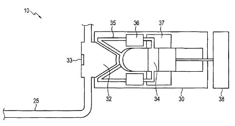
Fig. 1 is schematic diagram of a system for recovering energy from wellhead
gas,
in accordance with the present invention;
Fig. 2 is a schematic diagram of a Stirling engine in accordance with the
present
2o invention, connected to an output shaft;
CA 02522428 2005-10-06
- Page 12 -
Fig. 3 is a schematic diagram of a stirling engine, in accordance with the
present
invention, connected to an electrical generator, supplying electrical power to
a
power grid;
Fig. 4 is a schematic diagram of a further embodiment of a system in
accordance
with the present invention comprising a compressor and a pressure vessel; and
Fig. 5 is a schematic diagram of a further embodiment of a system in
accordance
with the present invention wherein a plurality of stirling engines are fueled
with
to wellhead gas.
DETAILED DESCRIPTION O)F THE ILLUSTRATED EMBODIMENTS
Fig 1 is a schematic illustration of a system 10 for recovering energy from
wellhead gas.
The energy recovery system ZO comprises a gas conduit 25 and a stirling engine
30. The
gas conduit 25 transfers raw wellhead gas, collected as a by-product from oil
producing
wells, from a wellhead 20 to the stirling engine 30.
The raw wellhead gas is collected from the top of the wellhead as is imown in
the art and
typically comprises a mixture of methane, ethane, propane, nitrogen, carbon-
dioxide,
helium, and other compounds. In addition, the raw wellhead gas may contain
small
quantities of water vapor and/or significant amounts of hydrogen sulfide (HzS)
making
CA 02522428 2005-10-06
- Page 13 -
the wellhead gas "sour gas". Typically, wellhead gas with a hydrogen sulfide
content
exceeding 5.7 milligrams per meter of gas is typically considered to be "sour
gas". The
pressure of the raw wellhead gas collected from the wellhead is typically 2
psi or slightly
higher, allowing the raw wellhead gas to move through the gas conduit 25
without
requiring additional compression, although the pressure of the raw wellhead
gas leaving
the wellhead can vary quite significantly.
The stirling engine 30 is a Stirling engine as is conventionally known and
could have
various configuration, however, stirling engine 30 typically comprises: at
least one
l0 combustion chamber 32; a combustor 33; one or more pistons 34; a heater
portion 35;
typically a regenerator 36; a cooling portion 37 and a power collecting unit
38. Although
the stirling engine 30 is illustrated as a beta configuration Stirling engine,
Stirling engine
30 could be any type of configuration, as is know for Stirling engines,
including alpha,
beta, gamma, rinia alpha configuration, or other Stirling engine
configuration.
In operation, the raw wellhead gas is transferred from wellhead (not shown)
through the
gas conduit 25 and into the combustion chamber 32 of the Stirling engine 30.
Once the
wellhead gas enters the combustion chamber 32, the raw wellhead gas is ignited
by the
combustor 33. This ignited wellhead gas is used as the heat source for the
Stirling engine
30.
CA 02522428 2005-10-06
- Page i4 -
Typically, the wellhead gas will be collected from a wellhead casing (not
shown) as a by-
product of the collection of oil from the well, however, wellhead gas can also
be released
during the drilling and preparation of the well for the production process and
wellhead
gas collected during the drilling and/or preparation of the well, could also
be used and
supplied through the gas conduit 25 to the combustion chamber 32 where it is
ignited and
used as the heat source to drive the Stirling engine 30.
As is typical for Stirling engines, the heat source is used to transfer
thermal energy to a
heating portion 35 containing a working fluid. Wellhead gas, ignited in the
combustion
l0 chamber 32 by the combustor 33, forms the heat source and a portion of the
thermal
energy released by the burning of the wellhead gas is transferred to working
fluid in the
heating portion 35 of the stirling engine 30. The heated working fluid then
drives the
pistons 34 and the working fluid is then recirculated through the cooling
portion 37.
Although the stirling engine 30 in Fig. 1 is illustrated with a single piston
34, it is known
by those skilled in the art that some configurations of Stirling engines
contain multiple
piston arrangements and stirling engines with more than one piston could be
used in the
present invention.
Although it is not necessary for a Stirling engine to comprises a regenerator
36, many do
to improve their operation, such as sterling engines in the beta configuration
and a Stirling
engine 30 may be used that does not have a regenerator 36.
CA 02522428 2005-10-06
- Page 15 -
The fluid in the heating portion 35, poling portion 37 and piston 34 is not in
fluid
communication with the combustion chamber 32 so the corrosive wellhead gas
being
ignited by the sterling engine 30 does not to affect the internal workings of
the pistons 34
of the Stirling engine 30 and no combustion of gases occurs in the pistons 34
or any other
part of the Stirling engine 30, with the exception of the combustion chamber
32.
The stirling engine 30 is driven by the heat source created by the ignited
wellhead gas
and the output of the Stirling engine is harnessed by the power collecting
unit 38. Fig. 2
illustrates a stirling engine 30, in accordance with the present invention,
where the
to displacement of the piston 34 is harnessed mechanical energy, such as by
rotating a
output shaft using a rombic drive 39, although other devices could be used to
harness the
mechanical power such as a swash plate drive (not shown).
Fig. 3 illustrates a Stirling engine 30, in accordance with the present
invention, wherein
t5 the displacement of the piston 34 is harnessed to drive a generator 40 and
output
electrical energy. The generator 40 introduces a load in the form of a linear
alternator
coils 42, wherein the passing of magnets 44 past the tinear alternator coils
42 create an
electrical current. This electrical current can then be used either to power
devices onsite
or, as shown in Fig. 3, processed through a transformer 50 and connected to an
electrical
20 grid 55, to pass the electrical energy back to the electrical grid 55.
CA 02522428 2005-10-06
- Page 16 -
Fig. 4 illustrates a further embodiment of the present invention, for use when
the supply
of wellhead gas is relatively unsteady. Energy recovery system 100 comprises:
a gas
conduit 25, a compressor 110; a pressure vessel 115; a pressure regulator
valve 120; and
a Stirling engine 30.
Some oil producing wells may produce a relatively unsteady supply of raw
wellhead gas,
wherein the pressure of the wellhead gas exiting the wellhead casing can
fluctuate
substantially. The supply of raw wellhead gas can fluctuate from pressures
above 2 psi to
much lower; so low that the raw wellhead gas will not move through the gas
conduit 25
t0 or allow adequate combustion by a combustor (not shown) of the Stirling
engine 30.
The raw wellhead gas is transported from the well head or well bore (not
shown) through
the gas conduit 25 to the compressor 110. The compressor 110 compresses the
wellhead
gas to a higher pressure and passes the pressurized wellhead gas to the
pressure vessel.
A pressure regulator valve 120 is provided in proximity to the exit of the
pressure vessel
115 to allow wellhead gas at a predetermined pressure to be transported into a
combustion chamber (not shown) of the Stirling engine 30, where the compressed
wellhead gas is ignited to drive the starling engine 30 and the power
generated by the
2o Stirling engine 30 can be harnessed, as described above.
CA 02522428 2005-10-06
Page 17 -
Using the power recovery system 100, raw wellhead gas can be used when the raw
wellhead gas is supplied at a relatively unsteady rate. The pressure vessel
115 stores
compressed wellhead gas so the supply of wellhead gas to the Stirling engine
30 is
regulated. The size of the pressure vessel i15, the pressure the wellhead gas
is
compressed to by the compressor 110 and/or the settings of the pressure
regulator valve
120 will determine the amount of time the Stirling engine 30 can be supplied
with a
sufficient flow of weilhead gas when the raw wellhead gas supplied from a
welihead (not
shown) drops below a suitable pressure.
1o Fig. 5 illustrates a further embodiment of the present invention, wherein
the pressure of
the raw wellhead gas is greater than required for the operation of a single
stirling engine
30. System 200 comprises a gas conduit 25; a first pressure regulator valve
210; a first
stirling engine 30A; a second pressure regulator valve 220; and a second
Stirling engine
30B.
is
Wellhead gas is supplied to the first stirling engine 30A and second Stirling
engine 30B
by the gas conduit 25. The first pressure regulator valve 210 controls the
flow of
wellhead gas to the first Stirling engine 30A. The remaining flow of wellhead
gas that
does not pass through the first pressure regulator valve 210 will flow through
the second
2o regulator valve 220 and to the second Stirling engine 30B. In this manner,
wellhead gas
can be supplied to multiple Stirling engines 30A and 30B and multiple Stirling
engines
30A and 30B can be used to generate power using the wellhead gas as fuel.
CA 02522428 2005-10-06
- Page 18 -
Although Fig. 5 illustrates two stirling engines 30A and 30B, it will be
apparent to a
person skilled in the art that more than two stirling engines could be used in
the same
manner, providing the supply of wellhead gas is sufficient to fuel the
additional stirling
engines.
The foregoing is considered as illustrative only of the principles of the
invention.
Further, since numerous changes and modifications will readily occur to those
skilled in
the art, it is not desired to limit the invention to the exact construction
and operation
l0 shown and described, and accordingly, all such suitable changes or
modifications in
structure or operation which may be resorted to are intended to fall within
the scope of
the claimed invention.