Language selection

Search

Patent 2522491 Summary

Third-party information liability

Some of the information on this Web page has been provided by external sources. The Government of Canada is not responsible for the accuracy, reliability or currency of the information supplied by external sources. Users wishing to rely upon this information should consult directly with the source of the information. Content provided by external sources is not subject to official languages, privacy and accessibility requirements.

Claims and Abstract availability

Any discrepancies in the text and image of the Claims and Abstract are due to differing posting times. Text of the Claims and Abstract are posted:

  • At the time the application is open to public inspection;
  • At the time of issue of the patent (grant).
(12) Patent: (11) CA 2522491
(54) English Title: SUPPORT DEVICE FOR ASSEMBLY OF A VEHICLE SECTION
(54) French Title: SUPPORT DE MONTAGE D'UNE SECTION DE VEHICULE
Status: Deemed expired
Bibliographic Data
(51) International Patent Classification (IPC):
  • B62D 65/06 (2006.01)
(72) Inventors :
  • ZEINSTRA, BRIAN (Canada)
  • TRACEY, DAVE (Canada)
(73) Owners :
  • HONDA MOTOR CO., LTD. (Japan)
(71) Applicants :
  • HONDA MOTOR CO., LTD. (Japan)
(74) Agent: GASTLE AND ASSOCIATES
(74) Associate agent:
(45) Issued: 2009-01-13
(22) Filed Date: 2005-10-07
(41) Open to Public Inspection: 2007-04-07
Examination requested: 2005-10-07
Availability of licence: N/A
(25) Language of filing: English

Patent Cooperation Treaty (PCT): No

(30) Application Priority Data: None

Abstracts

English Abstract

Disclosed is a device for supporting a tail gate section of a pick up vehicle during assembly thereof, including a pair of first coupling portions aligned with a first axis, each first coupling portion operable for coupling one of a pair of opposed end regions of a bed of the vehicle, a pair of second coupling portions aligned with a second axis, each second coupling portion operable for coupling one of a pair of opposed end regions of the tail gate section; and a deployment assembly joining the first and second coupling portions, the deployment assembly being operable in a first phase to rotate the second coupling portion about the first axis and a second phase to rotate the second coupling portions about the second axis.


French Abstract

Il s'agit d'un dispositif pour supporter une section de hayon d'une camionnette durant le montage, comprenant une paire de premiers tronçons d'accouplement alignés avec un premier axe, chaque premier tronçon d'accouplement pouvant fonctionner pour le couplage d'une de deux régions d'extrémités opposées d'un châssis du véhicule, une paire de deuxièmes tronçons d'accouplement alignée avec un deuxième axe, chaque deuxième tronçon d'accouplement pouvant fonctionner pour le couplage d'une de deux régions d'extrémités opposées de la section de hayon; et un dispositif de déploiement rattachant le premier et le deuxième tronçon d'accouplement, le dispositif de déploiement pouvant fonctionner dans une première phase pour faire pivoter le deuxième tronçon d'accouplement autour du premier axe et une deuxième phase pour faire pivoter le deuxième tronçon d'accouplement autour du deuxième axe.

Claims

Note: Claims are shown in the official language in which they were submitted.


CLAIMS:


1. A device for supporting a tail gate section of a pick up vehicle during
assembly thereof,
comprising a pair of first coupling portions aligned with a first axis, each
first coupling
portion operable for coupling one of a pair of opposed end regions of a bed of
the vehicle, a
pair of second coupling portions aligned with a second axis, each second
coupling portion
operable for coupling one of a pair of opposed end regions of the tail gate
section; and a
deployment assembly joining the first and second coupling portions, the
deployment assembly
being operable in a first phase to rotate the second coupling portion about
the first axis and a
second phase to rotate the second coupling portions about the second axis.


2. A device as defined in claim 1, wherein each end region includes first and
second end region
passages, each fust coupling portion including an anchor hook for engaging the
first end
region passage and a mounting pin for engaging the second end region passage.


3. A device as defined in claim 1, wherein each first coupling portion
includes a first body with
a plurality of anchor formations, each corresponding to a predetermined
operative orientation.

4. A device as defined in claim 3, wherein the deployment assembly includes an
arm having a
first end region pivotally mounted to the first body, and a positioning
element mounted on the
arm for movement relative thereto to engage the plurality of anchor formations
with the arm
in different operative orientations.


5. A device as defined in claim 4, the arm further comprising a plurality of
first support flanges
to support the positioning element on the arm.


6. A device as defined in claim 5, wherein the positioning element is a rod.


13


7. A device as defined in claim 6, further comprising an actuating handle for
actuating the rod.

8. A device as defined in claim 7, further comprising at least one guide tab
for holding the
actuating handle in at least one operative position.


9. A device as defined in claim 8, wherein the first body includes a
peripheral region and the
anchor formations include webs extending outwardly from the first body, each
web having a
passage therein to receive the actuating rod.


10. A device as defined in claim 4, wherein the arm is operable to sweep
between a lower
position and an upper position about the first axis, the device further
including a biasing
portion for biasing the arm toward the upper position.


11. A device as defined in claim 10, wherein the biasing portion includes a
coil spring mounted
between the arm and the first body.


12. A device as defined in claim 11, wherein each arm has a second end region,
each second
coupling portion includes a second body pivotally mounted to the second end
region of a
corresponding arm.


13. A device as defined in claim 12, further comprising a lateral support
member extending
between the second bodies.


14. A device as defined in claim 13, further comprising a plurality of
engaging members
positioned on the lateral support member for engaging a central portion of the
tail gate
section.


14


15. A device as defined in claim 14, further comprising a catch member
positioned adjacent each
second body for removably securing the tail gate section thereto.


16. A device as defined in claim 15, further comprising a plurality of
formations associated with
the second body, each formation corresponding to a predetermined operative
orientation of
the second body about the second axis.


17. A device as defined in claim 16, further comprising an actuator for
engaging each of the
formations for locking the second body in the predetermined orientation.


18. A device as defined in claim 17, wherein the second body includes a planar
member, the
formations including passages in the planar member.


19. A device as defined in claim 18, wherein the actuator includes a spring
loaded pin mounted on
the arm and aligned with each of the passages.


20. A device as defined in claim 10, further comprising a support brace
extending between the
arms near the first axis.


21. A device for supporting a tail gate section of a pick up vehicle during
assembly thereof,
comprising a pair of first coupling portions aligned with a first axis, each
first coupling
portion operable for coupling one of a pair of opposed end regions of a bed of
the vehicle, a
pair of second coupling portions aligned with a second axis, each second
coupling portion
operable for coupling one of a pair of opposed end regions of the tail gate
section; and a
deployment assembly joining the fust and second coupling portions, the
deployment assembly
being operable in a first phase to rotate the second coupling portion about
the first axis to
displace the tail gate section along a travel path between two positions on
opposite sides of


15


the opposed end regions, and a second phase to rotate the second coupling
portions about the
second axis.


22. A device as defined in claim 21, wherein each end region of the bed
includes first and second
end region passages, each first coupling portion including an anchor hook for
engaging the
first end region passage and a mounting pin for engaging the second end region
passage.


23. A device as defined in claim 21, wherein each first coupling portion
includes a first body with
a plurality of anchor formations, each corresponding to a predetermined
operative orientation.

24. A device as defined in claim 23, wherein the deployment assembly includes
an arm having a
first end region pivotally mounted to the first body, and a positioning
element mounted on the
arm for movement relative thereto to engage the plurality of anchor formations
with the arm
in different operative orientations.


25. A device as defined in claim 24, the arm further comprising a plurality of
first support flanges
to support the positioning element on the arm.


26. A device as defined in claim 24, wherein the arm is operable to sweep
between a lower
position and an upper position about the first axis, the device further
including a biasing
portion for biasing the arm toward the upper position.


27. A method of supporting a tail gate section of-a pick up vehicle during
assembly thereof,
comprising the steps of:

providing a pair of first coupling portions aligned with a first axis;


16


- installing each first coupling portion on a corresponding one of a pair of
opposed
end regions of a bed of the vehicle;

- providing a pair of second coupling portions aligned with a second axis;
installing each second coupling portion on a corresponding one of a pair of
opposed end regions of the tail gate section;

- providing a deployment assembly joining the first and second coupling
portions;
and

- manipulating the deployment assembly a first phase to rotate the second
coupling
portion about the first axis and a second phase to rotate the second coupling
portions about the second axis.


28. A method as defined in claim 27, wherein each end region of the bed
includes first and second
end region passages, and further comprising the steps of providing each first
coupling portion
with an anchor hook, engaging the anchor hook with the fust end region
passage, providing a
mounting pin and engaging the mounting pin with the second end region passage.


29. A method as defined in claim 27, further comprising the step of providing
each first coupling
portion with a first body having a plurality of anchor formations, each
corresponding to a
predetermined operative orientation.


30. A method as defined in claim 29, further comprising the steps of providing
the deployment
assembly with an arm having a first end region pivotally mounted to the first
body, providing
a positioning element mounted on the arm, and moving the positioning element
relative to the
arm to engage the plurality of anchor formations with the arm between
operative orientations.

17


31. A method as defined in claim 30, further comprising the step of providing
a plurality of first
support flanges to support the positioning element on the arm.


32. A method as defined in claim 31, further comprising the steps of
displacing the arm between a
lower position and an upper position about the first axis, and providing a
biasing portion for
biasing the arm toward the upper position.


33. A device for supporting a closure section of a vehicle, comprising a pair
of first coupling
portions aligned with a first axis, each first coupling portion operable for
coupling one of a
pair of opposed end regions of a support portion of the vehicle, a pair of
second coupling
portions aligned with a second axis, each second coupling portion operable for
coupling one
of a pair of opposed end regions of the closure section; and a deployment
assembly joining
the first and second coupling portions, the deployment assembly being operable
in a first
phase to rotate the second coupling portion about the first axis and a second
phase to rotate
the second coupling portions about the second axis.


34. A device as defined in claim 33, wherein the closure section includes one
or more than one of:
a hood panel or a portion thereof, a door panel or a portion thereof, a trank
panel or a portion
thereof.


35. A device as defined in claim 33, wherein each end region of the support
portion includes first
and second end region passages, each first coupling portion including an
anchor hook for
engaging the first end region passage and a mounting pin for engaging the
second end region
passage.


36. A device as defined in claim 33, wherein each first coupling portion
includes a first body with
a plurality of anchor formations, each corresponding to a predetermined
operative orientation.

18


37. A device as defined in claim 36, wherein the deployment assembly includes
an arm having a
first end region pivotally mounted to the first body, and a positioning
element mounted on the
arm for movement relative thereto to engage the plurality of anchor formations
with the arm
in different operative orientations.


38. A device as defined in claim 37, the arm further comprising a plurality of
first support flanges
to support the positioning element on the arm.


39. A device as defined in claim 37, wherein the arm is operable to sweep
between a lower
position and an upper position about the first axis, the device further
including a biasing
portion for biasing the arm toward the upper position.


40. A device for supporting a vehicle section during assembly thereof,
comprising a pair of first
coupling portions aligned with a first axis, each first coupling portion
operable for coupling
one of a pair of opposed end regions of a support portion of the vehicle, a
pair of second
coupling portions aligned with a second axis, each second coupling portion
operable for
coupling one of a pair of opposed end regions of the vehicle section; and a
deployment
assembly joining the first and second coupling portions, the deployment
assembly being
operable in a first phase to rotate the second coupling portion about the
first axis to displace
the vehicle section along a travel path between two positions on opposite
sides of the opposed
end regions, and a second phase to rotate the second coupling portions about
the second axis.


41. A device as defined in claim 40, wherein each end region of the support
portion includes first
and second end region passages, each first coupling portion including an
anchor hook for
engaging the first end region passage and a mounting pin for engaging the
second end region
passage.


19


42. A device as defined in claim 40, wherein each first coupling portion
includes a first body with
a plurality of anchor formations, each corresponding to a predetermined
operative orientation.


43. A device as defined in claim 42, wherein the deployment assembly includes
an arm having a
first end region pivotally mounted to the first body, and a positioning
element mounted on the
arm for movement relative thereto to engage the plurality of anchor formations
with the arm
in different operative orientations.


44. A device as defined in claim 43, the arm further comprising a plurality of
first support flanges
to support the positioning element on the arm.


45. A device as defined in claim 43, wherein the arm is operable to sweep
between a lower
position and an upper position about the first axis, the device further
including a biasing
portion for biasing the arm toward the upper position.


46. A method of supporting a section of a vehicle during assembly thereof,
comprising the steps
of

- providing a pair of first coupling portions aligned with a first axis;

- installing each first coupling portion on a corresponding one of a pair of
opposed
end regions of a support portion of the vehicle;

- providing a pair of second coupling portions aligned with a second axis;
- installing each second coupling portion on a corresponding one of a pair of
opposed end regions of the section;


20


- providing a deployment assembly joining the first and second coupling
portions;
and

- manipulating the deployment assembly a first phase to rotate the second
coupling
portion about the first axis and a second phase to rotate the second coupling
portions about the second axis.


47. A method as defined in claim 46, wherein each end region of the support
portion includes first
and second end region passages, and further comprising the steps of providing
each first
coupling portion with an anchor hook, engaging the anchor hook with the first
end region
passage, providing a mounting pin and engaging the mounting pin with the
second end region
passage.


48. A method as defined in claim 46, further comprising the step of providing
each first coupling
portion with a first body having a plurality of anchor formations, each
corresponding to a
predetermined operative orientation.


49. A method as defined in claim 48, further comprising the steps of providing
the deployment
assembly with an arm having a first end region pivotally mounted to the fust
body, providing
a positioning element mounted on the arm, and moving the positioning clement
relative to the
arm to engage the plurality of anchor formations with the arm between
operative orientations.


50. A method as defined in claim 49, further comprising the step of providing
a plurality of first
support flanges to support the positioning element on the arm.


51. A method as defined in claim 50, further comprising the steps of
displacing the arm between a
lower position and an upper position about the first axis, and providing a
biasing portion for
biasing the arm toward the upper position.


21

Description

Note: Descriptions are shown in the official language in which they were submitted.


CA 02522491 2008-01-31

SUPPORT DEVICE FOR ASSEMBLY OF A VEHICLE SECTION
BACKGROUND OF THE INVENTION

1. FIELD OF THE INVENTION

The present invention relates to fixtures for supporting work pieces, and more
particularly to fixtures for.
supporting closure panel members on vehicles, such as for example tail gates
on an end region of a rear bed
of a pick up truck vehicle.


2. DESCRIPTION OF THE RELATED ART

The assembly of "pick up" truck vehicles involves, among matty other steps,
the assembly and mounting of
tail gates. In some cases, the tail gate may be partially or fully fabricated
andlor painted before it is

installed on the vehicle. In other cases, it may be advantageous to install
components or part of the tail gate
after it has been mounted on the vehicle to optimize assembly line flow.
However, doing so does makes it
difficult for assembly Associates to work on the vehicles without awkward
lifting and/or reaching actions
which risk personal injury. It is also important to support the tail gate in a
manner to avoid twisting or
being that can cause deformation or other damage. To avoid these problems, it
is common to provide one

or more subassembly areas to allow for assembly and painting steps. Thus, the
tail gate tends to be a
particularly challenging vehicle part because it usually cannot be permanently
installed to the chassis in the
weld department, since doing so makes it awkward, at best, to paint and
finish.

It would thus be desirable to provide a novel approach to supporting a tail
gate to mitigate at least one of
these concerns.

SUMMARY OF THE INVENTION
{

HON-TBF/CDA 1
{


CA 02522491 2008-01-31

In one of its aspects, the present invention provides a device for supporting
a tail gate section of a pick up
vehicle during assembly thereof, comprising a pair of first. coupling portions
aligned with a first axis, each
first coupling portion operable for coupling one of a pair of opposed end
regions of a bed of the vehicle, a
pair of second coupling portions aligned with a second axis, each second
coupling portion operable for

coupling one of a pair of opposed end regions of the tail gate section; and a
deployment assembly joining
the first and second coupling portions, the deployment assembly being operable
in a first phase to rotate the
second coupling portion about the first axis and a second phase to rotate the
second coupling portions about

. ,
the second axis. -

=

In one embodiment, each end region includes first and second end region
passages, each first coupling
portion including an anchor hook for engaging the first end region passage and
a mounting pin for engaging
the second end region passage.

In one embodiment, each first coupling portion includes a first body with a
plurality of anchor formations,
each corresponding to a predetermined operative orientation.

In one embodiment, the deployment assembly includes an arm having a first end
region pivotally mounted
to the first body, and a positioning element mounted on the arm for movement
relative thereto to engage the
plurality of anchor formations with the arm in different operative
orientations.

In one embodiment, arm further comprises a plurality of first support flanges
to support the positioning
element on the arm.

In one embodiment, the positioning element is a rod.

An embodiment further comprises an actuating handle for actuating the rod.
HON-TBF/CDA 2


CA 02522491 2008-01-31

An embodiment further comprises at least one guide tab for holding the
actuating handle in at least one
operative position.

In one embodiment, the first body includes a peripheral region and the anchor
fotmations include webs
extending outwardly from the first body, each web having a passage therein to
receive the actuating rod.

In one embodiment, the arm is operable to sweep between a lower position and
an upper position about the
first axis, the device further including a biasing portion for biasing the arm
toward the upper position.

In one embodiment; the biasing portion includes a coil spring mounted between
the arm and the first body.
In one embodiment, each arm has a second end region; each second coupling
portion includes a second
body pivotally mounted to the second end region of a corresponding arm,

An embodiment further comprises a lateral support member extending between the
second bodies.
An embodiment fixrther comprises a plurality of engaging members positioned on
the lateral support
member for engaging a central portion of the tail gate section.

An embodiment further comprises a catch member positioned adjacent each second
body for removably
securing the tail gate section thereto.

An embodiment further comprises a plurality of formations associated with the
second body, each
formation corresponding to a predeternuned operative orientation of the second
body about the second axis.

An embodiment further comprises an actuator for engaging each of the
formations for locking the second
body in the predetermined orientation.

HON-TBF/CDA 3


CA 02522491 2008-01-31

In one embodiment, the second body includes a planar member, the formations
including passages in the
planar member.

In one embodiment, the actuator includes a spring loaded pin mounted on the
arm and aligned with each of
the passages.


An embodiment fiuther comprises a support brace extending between the arms
near the fust axis.

In yet another of its aspects, the present invention provides a device for
supporting a tail gate section of a
pick up vehicle during assembly thereof, comprising a pair of first coupling
portions aligned with a fust
axis, each first coupling portion operable for coupling one of a pair of
opposed end regions of a bed of the

vehicle, a pair of second coupling portions aligned with a second axis, each
second coupling portion
operable for coupling one of a pair of opposed end regions of the tail gate
section; and a deployment
assembly joining the first and second coupling portions, the deployment
assembly being operable in a first
phase to rotate the second coupling portion about the first axis to displace
the tail gate section along a travel

path between two positions on opposite sides of the opposed end regions, and a
second phase to rotate the
second coupling portions about the second axis.

In yet another of its aspects, the present invention provides a method of
supporting a tail gate section of a
pick up vehicle during assembly thereof, comprising the steps of

providing a pair of fii-st coupling portions aligned with a first axis;

installing each first coupling portion on a corresponding one of a pair of
opposed
end regions of a bed of the vehicle;

providing a pair of second coupling portions aiigned with a second axis;
HON-TBF/CDA 4


CA 02522491 2008-01-31

- installing each second coupling portion on a corresponding one of a pair of
opposed end regions of the tail gate section;

providing a deployment assembly joining the fust and second coupling portions;
and

manipulating the deployment assembly a first phase to rotate the second
coupling
portion about the first axis and a second phase to rotate the second coupling
portions about the second axis.

ln yet another of its aspects, the present invention provides a device for
supporting a closure section of a
vehicle, comprising a pair of first coupling portions aligned with a first
axis, each fnst coupling portion
operable for coupling one of a pair of opposed end regions of a support
portion of the vehicle, a pair of
second coupling portions aligned with a second axis, eacb second coupling
portion operable for coupling

one of a pair of opposed_end regions of the closure section; and a deployment
assembly joining the first and
second coupling portions, the deployment assembly being operable in a first
phase to rotate the second
coupling portion about the first axis and a second phase to rotate the second
coupling portions about the
second axis.

In an embodiment, the closure section includes one or more than one of: a hood
panel or a portion thereof,
a door panel or a portion thereof~ a trunk panel or a portion thereof.

In yet another of its aspects, the present invention provides a device for
supporting a vehicle section during
assembly thereof, comprising a pair of first coupling portions aligned with a
first axis, each first coupling
portion operable for coupling one of a pair of opposed end regions of a
Support portion of the vehicle, a

pair of second coupling portions aligned with a second axis, each second
coupling portion operable for
coupling one of a pair of opposed end regions of the vehicle section; and a
deployment assembly joining
the fust and second coupling portions, the deployment assembly being operable
in a first phase to rotate the
HON-TBF/CDA 5


CA 02522491 2008-01-31

second coupling portion about the fu=st axis to displace the vehicle section
along a travel path between two
positions on opposite sides of the opposed end regions, and a second phase to
rotate the second coupling
portions about the second axis.

In yet another of its aspects, the present invention provides a method of
supporting a section of a vehicle
during assembly thereof, comprising the steps of

providing a pair of first coupling portions aligned with a first axis;

- installing each first coupling portion on a corresponding one of a pair of
opposed
end regions of a support portion of the vehicle;

- providing a pair of second coupling portions aligned with a second axis;

- installing each second coupling portion on a corresponding one of a.pair of
opposed end regions of the section;

- providing a deployment assembly joining the fust and second coupling
portions;
and

manipulating the deployment assembly a first phase to rotate the second
coupling
portion about the first axis and a second phase to rotate the second coupling
portions about the second axis.

BRIEF DESCRIPTION OF THE DRAWINGS

Several preferred embodiments of the present invention will now be described,
by way of example only,
with reference to the appended drawings in which:

6
HON-TBF/CDA


CA 02522491 2008-01-31

Figure I is a perspective view of a device for supporting a tail gate section
of a pick up vehicle;

Figure 2 and 3 are opposite fragmentary perspective views of a first coupling
portion of the device of figure

Figures 4, 5 and 6 are fragmentary perspective views of the first coupling
portion and a second coupling
portion in different operative orientations;

Figure 7 is a fragmentary perspective view of the second coupling portion;

Figure 8 is a schematic view of the device of figure 1 in several operative
positions;

Figure 9 is a fragmentary perspective assembly view of the second coupling
portions and the tail gate
section; and


Figure 10 is a scbematic view of the device of figuie I in several operative
positions with other vehicle
sections.

DESCRIPTION OF THE PREFERRED EMBODIMENTS

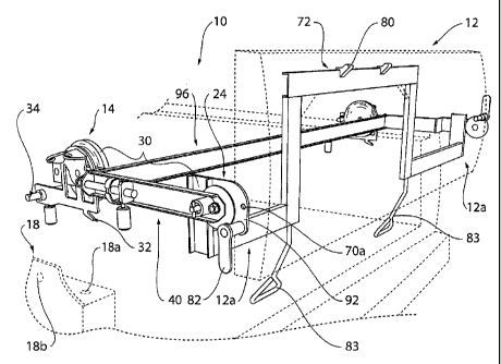
Referring to figure 1, there is provided a fixture device 10 for supporting a
tail gate section 12 of a pick up
vehicle during assembly thereof. The fixture device has a pair of first
coupling portions 14 aligned with a
first axis 16, as shown in figure 4. Referring to figures 1 and 2, each first
coupling portion 14 is operable

25, for coupling one of a pair of opposed end regions 18 of a bed 20 of the
vehicle 22, as will be described. A
pair of second coupling portions 24 are aligned with a second axis 26 (figure
7) and each second coupling
portion 24 is operable for coupling one of a pair of opposed end regions 12a
of the tail gate section 12.
Joining the fust and second coupling portions 14, 24 is a deployment assembly
30 which is operable in a
first phase to rotate the second coupling portions 24 about the fust axis 16
(as shown by the arrows in 16a

in figures 4 and 8) and a second phase to rotate the second coupling portions
24 about the second axis 26,
HON-TBF/CDA 7


CA 02522491 2008-01-31

as can be seen by arrow 26a in figures 7 and 8, thus providing the tail gate
section 12 at least two degrees
of freedom for movement.

Referring tofigures l and 2, each end region 18 of the vehicle includes first
and second end region
passages 18a, 18b. Conrespondingly, each ftt=st coupling portion 14 includes
an anchor hook 32 for
engaging the first end region passage 18a and a spring loaded mounting pin 34
for engaging the second end

region passage 18b. However, other arrangements may be used as discussed to
mount the device 10 on the
vehicle 22.

Referring to figure 3, each first coupling portion 14 includes a first body 36
with a plurality of anchor
formations 38, each of which corresponds to a predetermined operative
orientation, according to figures 3,
4,5and6.

Referring to figure 3, the deployment assembly 30 includes an arm 40 having a
first end region 40a

pivotally mounted to the first body 36, and a positioning element 42 mounted
on the arm 40 for movement
,i .
relative thereto to engage the plurality of anchor formations 38 with the arm
40 in different operative
orientations.

In this case, the positioning element 42 includes a rod 44 and the arm 40
includes three first support flanges
46 to support the rod thereon for movement between an engaged position and a
disengaged position, as will
be described. However, other mechanical arrangements may be employed to
position the arm 40 relative to
the first body 36.

Mounted on the rod between the fiust support flanges is an actuating handle 52
for actuating the rod 44.

At least one, in this case a pair, of guide tabs 54 are mounted on the arm 40
and is positioned adjacent the
actuating handle 52 for holding the latter in at least one operative position.

HON-TBFICDA 8


CA 02522491 2008-01-31

The first body 36 includes a peripheral region 36a and the anchor formations
38 include webs 56 extending
outwardly from the first body 36, each web having a passage 56a therein to
receivethe actuating rod 44.

It can be seen that the arm 40 is operable to sweep about the first axis 16
between a lower position shown
in figure 3 and an upper position, as shown in figure 5. Referring to figure
2, a biasing portion 60 is
provided as a lift assist, in this case including a coil spring 62, for
biasing the arm toward the upper
position. It can be seen that the coil spring 62 is mounted between an anchor
pin 64 mounted on the. arm 40

and a pivot pin 66 extending outwardly from the first body 36 and providing
the first axis 16. It will be
appreciated that the arm 40 has a passage not shown through which the pivot
pin extends, or is provided
with some other suitable pivoted connection with the first body 36. The coil
spring may be replaced with
other biasing portions, as desired, to assist in lifting the tail gate section
above the lower position.

Referring to figure 4, each ann 40 has a second end region 40b and each second
coupling portion 24
includes a second body 70 pivotally mounted thereto. Extending between the
second bodies 70 of the pair
of second coupling portions 24 is a lateral support member 72, as best seen in
figure 1, for supporting the
tail gate section-12 as will be described.

Continuing with reference to figure I, a plurality of (in this case two)
engaging members 80 are positioned
on the lateral support member 72 for engaging a central portion of the tail
gate section 12 as shown in

dashed lines in figure 1. In this case, the engaging members 80 take on the
form of hooks but could, if
desired, be replaced by othermeans such as other mechanical or non-mechanical
fasteners, such as magnets
for instance.

Referring to figures 1 and 4, a catch member 82 is located adjacent each
second body 70 for removably
securing the tail gate section 12 thereto. Also provided-is a pair of
manipulating handles 83 for orienting
the tail gate about both the first and second axes, as well be described.

HON-TBFICDA
9


CA 02522491 2008-01-31

Referring to figure 4, the second body 70 has a number of formations, in this
case second body passages
70a, which correspond to a predetermined operative orientation of the second
body 70 about the second
axis 26. An actuator 90 is provided for engaging each of the second body
passages 70a for locking the
second body 70 in any one of the predetermined orientations, as desired. The
second body 70 includes a

planar member 92 and it can be seen that the second body passages 70a are
located therein. In this case, the
actuator 90 includes a spring loaded pin 94 mounted within a sleeve 94a which
itself is located on the arm
40 and aligned with each of the second body passages 70a.

Referring to. figure 1, a support brace is also provided at 96 which extends
between the arms 40 near the
first axis 16 to provide additional support to the device 10.

The fixture device 10 is operated as follows. First, the device 10 is
installed on the end region 18, of a
vehicle 22 as it advances past a predetermined station along an assembly Gne.
This is done by aligning the
anchor hooks 32 on opposite first coupling portions in the corresponding first
end region passages 18a,

following with inserting the mounting.pins 34 in the corresponding second end
region passages 18b.
Next, the device 10 is placed in a particular orientation, such as that shown
in figure 1 where the arcns 40
are substantially horizontal thereby being accessible to an assembly associate
who is manipulation the tail
gate section 12, for example by directing a robotic tail gate section
manipulator, not shown. In either case,
the engaging members 80 are aligned with the corresponding passages in the
tail gate section and the catch
members 82 are then adjusted to engage complementary passages in the end
regions 12a.

As a result, the tail gate section 12 is now supported at a number of, in this
case four, locations adjacent the
lateral support member and can be manipulated in a number of ways to be
located in a number of
'orientations, some of which are shown in figure 8. For example, movement
about the first axis 16 is

engaged by displacing the actuator handle 52 from its position in figure 3 on
the left side of giuide tab 54 in
which the actuating rod 44 is fully engaged with the first web 56 which can be
seen to be at "three o'clock"-
by lifting the actuating handle 52 above the=guide tab 54.

HON-TBFlCUA 10


CA 02522491 2008-01-31

The actuator handle 52 is then displaced to the right as viewed in figure 3 to
the right side of the guide tab
54, causing the actuating rod 44 to be withdrawn from.the web 56 at "three
o'clock", thus releasing the ann
from the first coupling portion 14 for pivotal movement of the former about
axis 16. In this position, the
arm 44 may be swung up and locked in any one of the two other positions by
aligning the actuating rod 44

with the corresponding passage 56a and returning the actuating handle 52 to
its locked position on the left
hand side of the guide tab 54. This movement of the ann 44 is thus shown by
the various directional
arrows 16a in figure 8. Meanwhile, withdrawing the spring loaded pin 94
retracts it from an associated
passage 70a allowing the second coupling portion 24 to rotate relative to the
arms 40 under the guiding
force of the assembly associate via the manipulating handles 83.

Thus, in one form, the present device allows the tailgate to be installed
temporarily to the vehicle for
corrosion proofing, painting and assembly, providing the tail gate section 12
with at least two degrees of
freedom. This allows the tail gate section 12 to be manipulated between a
number of optimum positions,
depending on the fabrication, assembly and/or painting step, be it, for
example, the addition of a decal on a

rear face or the installation of lock hardware in an interior cavity. During
painting, the manipulating
handles may be used to orient the tail gate section without the need for
making physical contact with the
tail gate section, making the device 10 particularly suited for painting
fixtures in painting lines.

While the device 10 has been described with respect to a tail gate section of
a pick up vehicle, it will be
understood that the device and/or method may also be used for supporting other
sections of vehicles, such
as other closure sections. For example, the closure section may include one or
more than one of: a hood
panel or a portion thereof, a door panel or a portion thereof and/or a trunlc
panel or a portion thereof. The
section may also include other components such as an instrument panel, a
steering column, a seat and the
like.


While the present invention has been described for what are presently
considered the preferred
embodiments, the invention is not so limited. To the contrary, the invention
is intended to cover various
modifications and equivalent arrangements included within the spirit and scope
of the appended claims.
HON-TBF/CDA 11


CA 02522491 2008-01-31

The scope of the following claims is to be accorded the broadest
interpretation so as to encompass all such
modifications and equivalent structures and functions.

. '
HON-TBF/CDA 12

Representative Drawing
A single figure which represents the drawing illustrating the invention.
Administrative Status

For a clearer understanding of the status of the application/patent presented on this page, the site Disclaimer , as well as the definitions for Patent , Administrative Status , Maintenance Fee  and Payment History  should be consulted.

Administrative Status

Title Date
Forecasted Issue Date 2009-01-13
(22) Filed 2005-10-07
Examination Requested 2005-10-07
(41) Open to Public Inspection 2007-04-07
(45) Issued 2009-01-13
Deemed Expired 2020-10-07

Abandonment History

There is no abandonment history.

Payment History

Fee Type Anniversary Year Due Date Amount Paid Paid Date
Request for Examination $800.00 2005-10-07
Application Fee $400.00 2005-10-07
Registration of a document - section 124 $100.00 2006-03-30
Maintenance Fee - Application - New Act 2 2007-10-09 $100.00 2007-09-26
Maintenance Fee - Application - New Act 3 2008-10-07 $100.00 2008-09-19
Final Fee $300.00 2008-10-24
Maintenance Fee - Patent - New Act 4 2009-10-07 $100.00 2009-09-14
Maintenance Fee - Patent - New Act 5 2010-10-07 $200.00 2010-09-16
Maintenance Fee - Patent - New Act 6 2011-10-07 $200.00 2011-09-19
Maintenance Fee - Patent - New Act 7 2012-10-09 $200.00 2012-09-12
Maintenance Fee - Patent - New Act 8 2013-10-07 $200.00 2013-09-13
Maintenance Fee - Patent - New Act 9 2014-10-07 $200.00 2014-09-17
Maintenance Fee - Patent - New Act 10 2015-10-07 $250.00 2015-09-16
Maintenance Fee - Patent - New Act 11 2016-10-07 $250.00 2016-09-14
Maintenance Fee - Patent - New Act 12 2017-10-10 $250.00 2017-09-13
Maintenance Fee - Patent - New Act 13 2018-10-09 $250.00 2018-09-12
Maintenance Fee - Patent - New Act 14 2019-10-07 $250.00 2019-09-11
Owners on Record

Note: Records showing the ownership history in alphabetical order.

Current Owners on Record
HONDA MOTOR CO., LTD.
Past Owners on Record
TRACEY, DAVE
ZEINSTRA, BRIAN
Past Owners that do not appear in the "Owners on Record" listing will appear in other documentation within the application.
Documents

To view selected files, please enter reCAPTCHA code :


To view images, click a link in the Document Description column. To download the documents, select one or more checkboxes in the first column and then click the "Download Selected in PDF format (Zip Archive)" or the "Download Selected as Single PDF" button.

List of published and non-published patent-specific documents on the CPD .

If you have any difficulty accessing content, you can call the Client Service Centre at 1-866-997-1936 or send them an e-mail at CIPO Client Service Centre.


Document
Description 
Date
(yyyy-mm-dd) 
Number of pages   Size of Image (KB) 
Description 2008-01-31 12 397
Drawings 2008-01-31 10 183
Abstract 2008-01-31 1 17
Claims 2008-01-31 9 284
Abstract 2005-10-07 1 16
Description 2005-10-07 12 407
Claims 2005-10-07 6 165
Drawings 2005-10-07 10 182
Representative Drawing 2007-03-26 1 19
Cover Page 2007-03-29 1 47
Representative Drawing 2008-12-23 1 21
Cover Page 2008-12-23 1 48
Fees 2008-09-19 2 75
Assignment 2006-03-30 3 144
Correspondence 2005-11-18 1 25
Assignment 2005-10-07 2 70
Correspondence 2005-10-07 32 778
Prosecution-Amendment 2006-03-01 1 46
Prosecution-Amendment 2007-08-01 2 47
Fees 2007-09-26 1 59
Prosecution-Amendment 2008-01-31 34 938
Correspondence 2008-10-24 2 81