Note: Descriptions are shown in the official language in which they were submitted.
CA 02522806 2005-10-18
WO 2004/097288 PCT/US2004/012504
METHOD FOR CUTTING UNDERSEA PIPELINE TO LENGTH
CROSS-REFERENCE TO RELATED APPLICATION
[0001] The present patent disclosure is based upon and claims priority of U.S.
Provisional Application Serial No. 60/465,249 filed April 24, 2003, the
disclosures of
which are incorporated by reference.
BACKGROUND OF THE INVENTION
Field of the Invention
[0002] The present invention concerns the offshore laying of rigid pipeline on
the
seabed from a surface vessel and more particularly, a method for accurately
determining
the moment at which the pipeline has to be cut so that its end will land on
the seabed in
the target position defined by the client.
Description of Related Art
[0003] Pipelines are used to convey product between a first structure on the
seabed
and a second structure. When the second structure is located on the surface of
the sea,
these pipelines are called risers. When the second structure is located on the
seabed, these
pipelines are called flowlines. The present invention concerns more
particularly the
laying of flowlines.
[0004] Figures 1-3 show a l~nown method. Flowlines are laid on the seabed from
a
surface vessel. The flowline is laid from the vessel at an angle of about
10° to 60° from
the vertical depending on the laying method, the water depth, the metoceanic
conditions
and the characteristics of the flowline. It gently curves until it touches the
seabed at the
so-called Touch Down Point (TDP). The pipeline has a catenary shape. The
suspended
pipe catenary has a length L.
[0005] The length L is obviously greater than the water depth WD. The lateral
offset
D between the vertical of the vessel and the TDP is generally about 500 ft to
3,000 ft
(depending on the water depth) and a typical water depth can be up to 10,000
ft.
CA 02522806 2005-10-18
WO 2004/097288 PCT/US2004/012504
[0006] The structure on the seabed is usually a wellhead, manifold, riser
base, etc.
The flowline can be connected to this structure by two different methods: the
horizontal
connection and the vertical connection.
[0007] The horizontal connection consists in after having laid the flowline on
the
seabed, pulling its end to the horizontal flange of the seabed structure and
then
connecting the pipeline end to the structure.
[0008] The vertical connection consists in first laying the flowline on the
seabed.
The flowline comprises at each end a Pipe Line End Terminal (PLET). The PLET
consists, in its simplest form, of an elbow pipe having a vertical flange for
connection to
the vertical flange of the seabed structure.
[0009] To connect these two vertical flanges together, a U spool (jumper) is
used to
connect these two flanges. The flowline can also comprise an in-line tee (also
called an
in-line sled) for midline connection to a third subsea structure.
[0010] Whatever the method to be used for connecting the flowline to a subsea
structure, in order to male a connection to a sub.sea structure, the flowline
needs to be cut
on the vessel at a correct time and the connection means (such as PLET, flange
or inline
sled) welded to the flowline, so that the connection means will be positioned
accurately
on the seabed in the target position defined by the client and ready for
connection to the
subsea structure. The target position is generally a 10x10 to 15x15ft square
area (to be
compared with the thousands feet of lateral offset and water depth). It is
consequently
necessary to accurately know the position of the flowline on the seabed and
around the
coimection area to determine at what time. the flowline has to be cut on the
vessel so that
its connection means will land in the target position.
[0011] This requirement for the correct positioning in the target position
defined by
the client is particularly important in the vertical connection system, where
the jumper is
r
designed and built prior to the laying operation. Should the pipe connection
means not be
positioned in the target position, the jumper will have to be modified, which
delays the
completion of the project.
[0012] The lnown method consists in determining the exact position (two
coordinates) of the pipe end at the TDP where it first touches the seabed and
comparing it
-2-
CA 02522806 2005-10-18
WO 2004/097288 PCT/US2004/012504
with the lrnown coordinates of the target position to determine at what moment
to cut the
flowline and weld the connection.
[0013] On the seabed, a first array of 6 seabed transponders are arranged
around the
target position. A second array are arranged on the seabed around the
predicted TDP
upstream from the target position at a dista~ice D~ greater than L. If need
be, an
intermediate transponder can be arranged in between the two arrays for
allowing
communication between them.
[0014] To be able to determine the exact position of the flowline on the
seabed, the
exact position of these seabed transponders must be known. In order to do so,
the survey
vessel determines exactly the position of two seabed transponders per array
and then
based on these two l~nown seabed transponders, is able by interrogating the
seabed
transponders to determine the exact position of the other seabed transponders
by
comparing the distance separating them from each other. Installation of the
seabed
transponders and determination of their positions normally can take about two
days and
will require a survey vessel.
[0015] Then 3 pipe transponders are attached to the pipe so as to land within
the
second array of seabed transponders. When the pipe transponders land on the
sea bed, a
survey vessel (not shown) interrogates the seabed transponders of the second
array and
the pipe transponders in a relative mode to determinate the length separating
each of the
seabed transponders from the pipe transponders. When all the lengths are
known, the
exact position of the pipe transponders on the seabed is accurately lmown. To
know the
exact coordinates of a pipe transponder, requires the use of at least two
seabed
transponders. Preferably, three pipe transponders and six seabed transponders
are used
for redundancy and double checking purposes.
[0016] With the exact position of the pipe transponder(s), it is possible to
determine
the remaining length of flowline required to reach the target position by
comparing the
coordinates of the target position with the coordinates of the pipe
transponders.
[0017] When this remaining flowline length is reached, the flowline is cut on
the
laying vessel, the connection means is welded to the flowline and a fourth
transponder
(not shown) is attached to this connection means. The pipe is then dropped
onto the
seabed. The fourth pipe transponder is used to position accurately the pipe
connection
-3-
CA 02522806 2005-10-18
WO 2004/097288 PCT/US2004/012504
means in the target box by determining again the exact position of this fourth
pipe
transponder using the first array of seabed trausponders and comparing the
resulting
coordinates with the coordinates of the target position.
[0018] This prior art method gives very good results. Unfortunately , it is
time-
consuming, requires an additional vessel, typically a survey vessel amd
requires at least 2
days of vessel work before and after laying to install and recover the seabed
transponders
and requires more than 16 transponders (2x6 seabed transponders and 4 pipe
transponders).
SUMMARY OF THE INVENTION
[0019] The present invention relates to a new method for determining the
length at
which to cut the flowline for welding of the connection means. It reduces
dramatically
the number of required transponders and the time required to install and
recover the
transponders.
[0020] A central difference between the previous method and the present
invention is
that the previous method determines the exact position of the pipe
transponders and then
derives the required remaining length, which requires a large number of
transponders (at
least two seabed transponders to determine the exact coordinates of the pipe
transponders
and for redundancy reasons, preferably an array of 6 seabed transponders),
while with the
invention, only the distances separating the seabed transponders and the pipe
transponders are measured and compared to establish this remaining length.
[0021] It is possible to determine this length using only the distance
separating the
different transponders, as both seabed and pipe transponders are arranged on
the pipelay
route centerline rather than around the pipelay route as in the previous
method.
[0022] Other features and advantages of the present invention will become
apparent
from the following description of embodiments of the invention which refers to
the
accompanying drawings.
BRIEF DESCRIPTION OF THE DRAWINGS
[0023] Figure 1 illustrates schematically the basic elements of a prior art
method.
[0024] Figure 2 illustrates the layout of seabed transponders in the prior art
method.
-4-
CA 02522806 2005-10-18
WO 2004/097288 PCT/US2004/012504
[0025] Figure 3 shows the relative positions of pipeline transponders and
seabed
transponders in the prior art method.
[0026] Figure 4 illustrates the arrangement of seabed transponders and target
position
in a method according to an embodiment of the invention.
[0027] Figure 5 shows the laying of an undersea pipeline including pipeline
transponders according to the embodiment of Figure 4.
DETAILED DESCRIPTION OF AN EMBODIMENT OF THE INVENTION
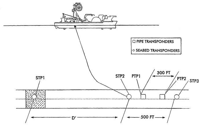
[0028] See Figures 4-5. A first seabed transponder STP1 is arranged on the
target
position, and then two (second and third) seabed transponders STP2 and STP3
are laid on
the pipelay route centreline spaced from the first transponder over a length
D~ greater
than the catenary length L between the TDP and the surface vessel.
[0029] A vessel, preferably the laying vessel during her preparation time,
installs and
determines the exact positions of these 3 seabed transponders and thus the
exact distances
separating these seabed transponders can be calculated.
[0030] During lay approach to the target area, two (first and second) pipe
transponders PTP 1 and PTP2 axe attached to the flowline in order to land in
between the
second and third seabed transponders.
[0031] A vessel, preferably the laying vessel, and more preferably the laying
vessel's
ROV (remote operated vehicle: underwater robot) then interrogates each of the
first and
second pipe transponders and second and third seabed transponders in a
relative mode to
establish the exact distances between them. In a preferred embodiment of the
invention, it
is sufficient to determine only the distance between PTP 1 and STP2, and the
distance
between PTP2 and STP3.
[0032] Based on these distances, the surveyor on the lay vessel will calculate
the
required remaining length of flowline by comparing the distance between the
first pipe
transponder and the second seabed transponder, and the distance between the
second and
first seabed transponders STP2 and STP1.
[0033] The fact that the pipe transponders land on the seabed in between the
second
and third seabed transponder in this embodiment does not limit the invention.
The pipe
transponders preferably land close enough to the seabed transponders to be
able to
-S-
CA 02522806 2005-10-18
WO 2004/097288 PCT/US2004/012504
establish the length separating them, and therefore can land before or after
the seabed
transponders.
[0034] A third pipe transponder (not showwrn) is attached at the end of the
flowline to
ensure that the end will be correctly positioned on the seabed. However, this
third pipe
transponder is not required, as long as the length is correct.
[0035] Should the flowline end land in a position laterally offset from the
target box,
the laying vessel during abandonment will merely have to pull up the flowline
and
position the flowline correctly in the target box.
[0036] Preferentially, the distance D~ between the first and second seabed
transponders is greater than the length L of the suspended pipe catenary.
Preferentially
the distance D~ will be comprised between L+300 ft and L+700ft. This
additional
distance allows the surveyor sufficient time to determine the remaining length
and allows
the pipelay superintendent to prepare the flowline cutting work and the
connection of the
pipe comlection means.
[0037] Preferentially the distance separating the second and third seabed
transponders
is about S00 ft. Preferentially the distance separating the first and second
pipe
transponders is about 300 ft. An important feature is that the distance
separating the
second and third seabed transponders is greater than the distance separating
the first and
second pipe transponders.
[0038] Main advantages, as compared to the prior method, are:
- fewer transponders required: 3 on the seabed and 2 on the flowline
- additional vessel (survey vessel) is not required. Transponders can be
installed
by the laying vessel during preparation time and the laying vessel's ROV can
be used to interrogate the transponders
- True distances separating the different transponders are accurately blown as
the seabed transponders are installed on the pipeline route centreline.
- As there is a seabed transponder on the target box, the distance separating
the
target box from the two other seabed transponders is always accurately
known. In the prior art system, the seabed transponders were arranged around
the target box and around the pipeline route but none of them were arranged
on the pipeline route centreline; and consequently, it was impossible to use
-6-
CA 02522806 2005-10-18
WO 2004/097288 PCT/US2004/012504
only the distance separating a seabed transponder from a pipe transponder to
establish this remaining length of pipeline.
[0039] An important difference from the prior art system is that the seabed
transponders are directly arranged on the pipelay route centreline so that the
distance
separating the different seabed and pipe transponders can be used to establish
the
remaining length of pipeline needed to reach the target position.
[0040] Although the present invention has been described in relation to
particular
embodiments thereof, marry other variations and modifications and other uses
will
become apparent to those skilled in the art. Therefore, the present invention
is not
limited by the specific disclosure herein.