Note: Descriptions are shown in the official language in which they were submitted.
CA 02522853 2005-10-19
c t
DESCRIPTION
FLUID CONTROLLER
TECHNICAL FIELD
The present invention relates to a fluid controller, in
particular, a fluid controller suitable for treating a large
flow rate of fluid.
BACKGROUND ART
A fluid controller to which the present invention is
directed is called as a diaphragm valve and is used frequently
( for example, refer to Patent Document 1 = Japanese Unexamined
Patent Publication No. 2003-42314). A typical structure
thereof is shown in Fig. 4.
A fluid controller 1 comprises a block-like main body 2
having a fluid inflow passage 2a, a fluid outflow passage 2b
and a concave portion 2c open upward, an annular valve seat 3
arranged in a peripheral edge of the fluid inflow passage 2a,
a diaphragm 4 pressed against or moved apart from the annular
valve seat 3 so as to open and close the fluid passage 2a, a
valve body presser foot 5 pressing the diaphragm 4 and capable
of moving in a vertical direction, a cylindrical hood 6 having
a lower end portion inserted to the concave portion 2c of the
main body 2 and extending upward, a tubular male thread member
-1-
CA 02522853 2005-10-19
7 screwed into a female thread portion formed in an inner periphery
of the concave portion 2c of the main body 2 so as to fix the
hood 6 to the main body 2 , a cover 8 covering the hood 6 existing
above the tubular male thread member 7 , a valve rod 9 inserted
into the hood 6 in a vertically movable manner, having a lower
end portion brought into contact with the valve body presser
foot 5 and having an upper end portion protruding upward from
the cover 8, an opening/closing handle 10 fixed to the upper
end portion of the valve rod 9 so as to be rotated, thereby moving
the valve rod 9 in a vertical direction, and a compression coil
spring 11 received between the lower end portion of the valve
rod 9 and the upper end portion of the hood 6 and biasing the
valve rod 9 downward.
The fluid inflow passage 2a of the main body 2 has one
end which is open toward a left side and the other end which
is open to a center portion of a bottom surface of the concave
portion 2c. The fluid outflow passage 2b has one end which is
open toward a right side and the other end which is open to a
right portion of the bottom surface of the concave portion 2c.
The cover 8 is formed into a cylindrical shape having a
top wall 8a, and a through hole inserting an upper end portion
of the valve rod 9 therethrough is provided in the top wall 8a.
The handle 10 is formed into an approximately oval shape as seen
from a plane, and is formed in a shape having a neck portion
10a in a center portion in a longitudinal direction. A
-2-
CA 02522853 2005-10-19
countersunk head screw 12 passing through a peripheral wall of
the cover 8 is screwed into a female thread provided in the hood
6, so that the cover 8 is fixed to the hood 6.
The valve rod 9 has a flange 9a in a lower end portion,
and a lower end portion of the hood 6 is provided with an inner
peripheral surface guiding the flange 9a in a vertically movable
manner and a step portion inhibiting the flange 9a from moving
above a predetermined position. A spring receiving ring 17 is
attached to a portion above the flange 9a of the valve rod 9
via a bearing 16. The compression coil spring 11 is received
by the spring receiving ring 17 and an annular step portion
provided in an upper portion of the hood 6.
A gap is provided between the top wall of the cover 8 and
the top surface of the hood 6 , a horizontal shaft 13 is passed
through the portion of the valve rod 9 positioned in this gap,
and a bearing 14 is attached to each of both end portions. A
guide surface 15 guiding the bearings Z4 and formed into an annular
shape as seen from a plane and into a smooth concavo-convex shape
in a height direction is formed in an upper end of the hood 6.
A pair of convex portions 15a existing at positions 180° apart
from each other in the guide surface 15 support the bearing 14.
The valve rod 9 is always biased downward by a compression
coil spring 11, and the bearing 14 is pressed against the guide
surface 15 on the basis of a biasing force. The guide surface
2 5 15 gradually becomes lower in height in accordance with a movement
-3-
CA 02522853 2005-10-19
in a circumferential direction from the convex portion 15a, and
has a concave portion 15b having a lowest height at a position
moved at 90° from the convex portion 15a in the circumferential
direction. The figure shows a fluid path closed state. A pair
of concave portions 15b in the guide surface 15 support the bearing
14. Accordingly, the valve rod 9 is positioned at a lower side,
that is, a fluid passage closing position. Further, when the
valve rod 9 becomes in a 90° rotated state from the state in
the figure, the bearing I4 moves on the guide surface 15 in a
state of being pressed against the guide surface 15 on the basis
of the biasing force of the compression coil spring 11, and after
being rotated at 90°, the pair of convex portions 15a in the
guide surface 15 support the bearing 14 . As a result , the valve
rod 9 is positioned at an upper side, that is, a fluid passage
opening position. Accordingly, the structure is made such that
the handle ZO is rotated at 90°, so that a closed state and an
open state can be switched.
In the conventional fluid controller 1 shown as one example
in Fig. 4, an opening in a concave portion side of the fluid
inflow passage 2a is faced to an inner side of the annular valve
seat 3, and an opening in a concave portion side of the fluid
outflow passage 2b is faced to an outer side of the annular valve
seat 3 , a maximum value ( about one third of a diaphragm diameter )
of each of the diameters of the openings are limited by the
diaphragm diameter ( a diameter of the concave portion ) . In order
-4-
CA 02522853 2005-10-19
to increase a flow rate coefficient or a Cv value, it is necessary
to increase the diameter of the opening in the concave portion
side of each of the passages 2a and 2b, that is, the diameter
of the diaphragm 4. Accordingly, it is necessary to make a size
of the fluid controller 1 large . However, in the existing device ,
there are many cases that the fluid controller can not be increased
in size due to a problem of an installation space, and it is
hard to make the flow rate large.
An object of the present invention is to provide a fluid
controller which can circulate a large flow rate of fluid without
enlarging its size.
DISCLOSURE OF THE INVENTION
In accordance with the present invention , there is provided
a fluid controller comprising: a block-like main body having
a fluid inflow passage, a fluid outflow passage and a concave
portion open upward; and a diaphragm pressed against or moved
apart from an annular valve seat arranged within the concave
portion of the main body so as to open and close the f luid passages ,
wherein the concave portion is formed into a shape including
a large-diameter portion close to the opening and a
small-diameter portion connected to a lower side of the
large-diameter portion via a step portion, and the fluid
controller is further provided with a flow path forming disk
fitted to the concave portion, the flow path forming disk includes
_5_
CA 02522853 2005-10-19
a large-diameter cylinder portion fitted to the large-diameter
portion of the concave portion in a fluid tight manner, a
small-diameter cylinder portion having an outer diametersmaller
than an inner diameter of the small-diameter portion of the
concave portion and having a lower end received by a bottom surface
of the concave portion , and a coupling portion coupling a lower
end portion of the large-diameter cylinder portion and an upper
end portion of the small-diameter cylinder portion and received
by the step portion of the concave portion, and a peripheral
edge portion of the diaphragm is fixed to an upper end portion
of the large-diameter cylinder portion of the flow path forming
disk, a valve seat is provided in the upper end portion of the
small-diameter cylinder portion of the flow path forming disk,
an inner annular space of the large-diameter cylinder portion
is formed by an inner periphery of the large-diameter cylinder
portion of the flow path forming disk, the diaphragm, the valve
seat and a top surface of the coupling portion of the flow path
forming disk, a plurality of through holes communicating an outer
annular space of the small-diameter cylinder portion formed
between the small-diameter cylinder portion of the flow path
forming disk and a peripheral surface of the small-diameter
portion of the concave portion with an inner annular space of
the large-diameter cylinder portion are formed in a coupling
portion of the flow path forming disk, any one of the fluid inflow
passage and the fluid outflow passage is communicated with a
-6-
CA 02522853 2005-10-19
lower end of the small-diameter cylinder portion of the flow
path forming disk, and the other is formed so as to be communicated
with the outer annular space of the small-diameter cylinder
portion.
A passage including an inner side of the small-diameter
cylinder portion, a portion between the valve seat and the
diaphragm , the inner annular space of the large-diameter cylinder
portion, the through holes of the coupling portion and the outer
annular space of the small-diameter cylinder portion is formed
between the fluid inflow passage and the fluid outflow passage
by the flow path forming disk. Among them, since a cross
sectional area of the small-diameter cylinder portion can be
made larger than the passage opening of the conventional
structure in which the openings of both of the fluid inflow passage
and the fluid outflow passage are faced to the bottom surface
of the concave portion, and the through holes of the coupling
portion are formed in the annular portion in the outer side of
the small-diameter cylinder portion, it is easy to set a total
sectional area to a comparable level with a cross sectional area
of the small-diameter cylinder portion, and it is possible to
make the cross sectional area of the passage larger in comparison
with the conventional structure.
In the fluid controller in accordance with the present
invention, an operation drive portion pressing the diaphragm
against the valve seat or moving the diaphragm apart from the
CA 02522853 2005-10-19
valve seat may be structured such as to manually move a valve
rod in a vertical direction, or move the valve rod in the vertical
direction by compressed air, solenoid or the like. Further,
the fluid controller may be of a normally open type or a normally
close type.
There is a case that the passage communicating with the
lower end of the small-diameter cylinder portion of the flow
path forming disk includes a short passage extending directly
below from the lower end of the small-diameter cylinder portion,
and a long passage extending to an outer side from a lower end
of the short passage so as to form an acute angle, and the passage
communicating with the outer annular space of the small-diameter
cylinder portion extends obliquely to a lower outer side from
the outer annular space of the small-diameter cylinder portion.
Further, there is a case that a joint portion having an
inclined passage communicating with the long passage is provided
in one side surface of the main body in a protruding manner,
and a joint portion having an inclined passage communicating
with the passage communicating with the outer annular space of
the small-diameter cylinder portion is provided in the other
side surface of the main body in a protruding manner.
It is preferable that a total cross sectional area of a
plurality of through holes in the vertical direction formed in
the coupling portion of the flow path forming disk is set to
0 . 5 to 2 . 0 times of the cross sectional area of the small-diameter
-g_
CA 02522853 2005-10-19
cylinder portion of the flow path forming disk. In accordance
with the structure mentioned above, it is possible to easily
obtain the fluid controller which is small and has a large flow
rate.
It is preferable that a seal member is interposed between
the lower end surface of the flow path forming disk and the bottom
surface of the concave portion of the main body. In this case,
it is more preferable that an annular seal projection brought
into close contact with each of upper and lower surfaces of the
seal member is formed in the lower end surface of the flow path
forming disk and the bottom surface of the concave portion of
the main body.
The seal member is constituted by a metal gasket , a Vickers
hardness thereof is preferably 80 to 200 Hv, more preferably
100 to 140 Hv. A Vickers hardness of the lower end surface of
the flow path forming disk and the bottom surface of the concave
portion of the main body is preferably 250 to 450 Hv, more
preferably 300 to 400 Hv. Further, it is preferable that the
seal projection is mirror finished, and it is preferable that
a Teflon coating is applied to the gasket.
In accordance with the fluid controller of the present
invention, since it is possible to make the cross sectional area
of the passage larger in comparison with the conventional
structure, it is possible to increase a flow rate coefficient
while keeping a size of the fluid controller fixed, or it is
-9-
CA 02522853 2005-10-19
possible to achieve a downsizing of the fluid controller while
keeping the flow rate coefficient.
BRIEF DESCRIPTION OF THE DRAWINGS
Fig. 1 is a vertical sectional view showing a first
embodiment of a fluid controller in accordance with the present
invention.
Fig. 2 is a plan view of the same.
Fig. 3 is a vertical sectional view showing a second
embodiment of the f luid controller in accordance with the present
invention.
Fig. 4 is a vertical sectional view showing a conventional
fluid controller targeted by the fluid controller in accordance
with the present invention.
BEST MODE FOR CARRYING OUT THE INVENTION
Description will be given below of embodiments in
accordance with the present invention with reference to the
accompanying drawings. In the following description,rightand
left mean right and left in the drawings.
Figs . 1 and 2 show one embodiment of a fluid controller
in accordance with the present invention.
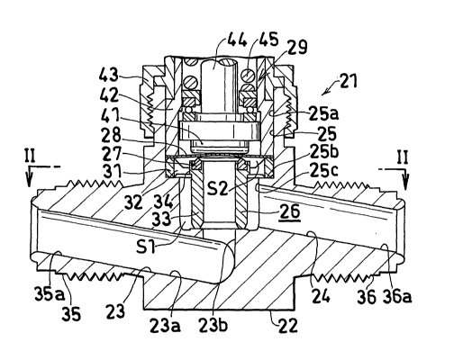
A fluid controller 21 comprises a block-like main body
22 having a fluid inflow passage 23, a fluid outflow passage
23 and a concave portion 25 open upward, a flow path forming
-10-
CA 02522853 2005-10-19
disk 26 fitted to the concave portion 25 of the main body 22,
an annular valve seat 27 arranged in the flow path forming disk
26 , a diaphragm 28 pressed against or moved apart from the valve
seat 27 so as to open and close the fluid passage 23, and an
operation driving portion pressing the diaphragm 28 against the
valve seat 27 or moving the diaphragm 28 apart from the valve
seat 27.
The concave portion 25 includes a large-diameter portion
25a close to the opening and a small-diameter portion 25c
IO connected to a lower side of the large-diameter portion 25a via
a step portion 25b.
The operation driving portion 29 is provided with a
diaphragm presser foot 41 pressing a center portion of the
diaphragm 28 and capable of moving in a vertical direction, a
cylindrical hood 42 having a lower end portion inserted to the
concave portion 22c of the main body 22 in such a manner as to
press a peripheral edge portion of the diaphragm 28 to a lower
side and extending upward, a hood nut 43 screwed into a male
thread portion formed in an outer periphery of the concave portion
22c of the main body 22 so as to fix the hood 42 to the main
body 22 , a valve rod 44 inserted into the hood 42 in a vertically
movable manner and having a lower end brought into contact with
the valve body presser foot 5, and a compression coil spring
45 biasing the valve rod 44 downward.
The flow path forming disk 26 includes a large-diameter
-11-
CA 02522853 2005-10-19
cylinder portion 31 fitted to the large-diameter portion 25a
of the concave portion in a fluid tight manner, a small-diameter
cylinder portion 33 having an outer diameter smaller than an
inner diameter of the small-diameter portion 25c of the concave
portion and having a lower end received by a bottom surface of
the concave portion 25, and a coupling portion 32 coupling a
lower end portion of an inner side surface of the large-diameter
cylinder portion 31 and an upper end portion of an outer side
surface of the small-diameter cylinder portion 33 and received
by the step portion 25b of the concave portion. Accordingly,
a small-diameter cylinder portion outer annular space S1 is
formed between the small-diameter cylinder portion 33 of the
flow path forming disk 26 and a peripheral surface of the
small-diameter portion 25c of the concave portion.
The valve seat 27 is provided in an upper end surface of
the small-diameter cylinder portion 33 of the flow path forming
disk 26 , and a leading end ( an upper end) thereof is set to have
an approximately the same height as that of an upper end of the
large-diameter cylinder portion 31 of the flow path forming disk
26. The diaphragm 28 is fixed to an upper end portion of the
large-diameter cylinder portion 31 of the flow path forming disk
26 in an outer peripheral edge portion thereof , and is structured
such as to be brought into contact with a leading end of the
valve seat 27 in an annular portion in an inner side in a radial
direction from an outer peripheral edge portion in the case of
-12-
CA 02522853 2005-10-19
being pressed downward by the diaphragm presser foot 41.
Accordingly, there isformed a large-diameter cylinder portion
inner annular space S2 surrounded by the inner periphery of the
large-diameter cylinder portion 31 of the flow path forming disk
26 , the diaphragm 28 , the valve seat 27 and the upper surface
of the coupling portion 32 of the flow path forming disk 26.
A plurality of through holes 34 in a vertical direction
communicating the small-diameter cylinder portion outer annular
space S1 and the large-diameter cylinder portion inner annular
space S2 are formed in the coupling portion 32 of the flow path
forming disk 26 at a uniform interval in a circumferential
direction, as shown in Fig. 2.
The fluid inflow path 23 includes a short passage 23b
extending directly below from the lower end opening of the
small-diameter cylinder portion 33 of the flow path forming disk
26, and a long passage 23a extending to a left side (an outer
side) so as to form an acute angle from a lower end of the short
passage 23b, so that the opening close to the concave portion
in the fluid inflow passage 23 is communicated with the lower
end of the small-diameter cylinder portion 33 of the flow path
forming disk 26. An inlet side joint portion 35 is provided
in a left side surface of the main body 22 in a protruding manner,
and a slope-shaped joint member inner passage 35a connected to
the long passage 23a of the fluid inflow passage 23 in an extending
manner is formed in the joint portion 35.
-13-
CA 02522853 2005-10-19
The fluid outflow passage 24b extends to a right lower
side (an obliquely lower outer side) from a right surface of
thesmall-diameter cylinder portion outer annularspace Sl. The
outlet side joint portion 36 is provided in a right side surface
of the main body 22 in a protruding manner, and a slope-shaped
joint member inner passage 36a connected to the fluid outflow
passage 24 in an extending manner is formed in the joint portion
36.
A male thread portion is provided in outer peripheries
of the joint portions 35 and 36 in the inlet side and the outlet
side. Shapes of the joint portions 35 and 36 are not limited
to them, but can employ various types.
In accordance with the fluid controller 21, in the flow
path open state in which the diaphragm presser foot 41 is moved
upward, the fluid flows through the joint portion inner passage
35a, the fluid inflow passage 23, the small-diameter cylinder
portion 33 of the flow path forming disk 26, the portion between
the valve seat 27 and the diaphragm 28, the large-diameter
cylinder portion inner annular space S2, the through hole 34
in the joint portion 32 of the flow path forming disk 26, the
small-diameter cylinder portion outer annular space S1, and the
joint portion inner passage 36a of the fluid outflow passage
24, in sequence. At this time, a size of the opening in the
side of each of the concave portions of the fluid inflow passage
23 and the fluid outflow passage 24 and a cross sectional area
-14-
CA 02522853 2005-10-19
of the communication path between the openings come to a neck
portion for a large flow rate. However, the opening area in
the side of the concave portion of the fluid inflow passage 23
can be enlarged at a degree that the fluid outflow passage 24
is not open to the bottom surface of the concave portion 25,
and a necessary size of the opening area in the side of the concave
portion of the fluid outflow passage 24 can be secured in a right
surface of the small-diameter cylinder portion outer annular
space S1. Further, a cross sectional area of the communication
path between the openings in the side of the concave portions
of the fluid inflow passage 23 and the fluid outflow passage
24 is secured in a total cross sectional area thereof by a plurality
of through holes 34 being formed in the annular coupling portion
32 , and both of the small-diameter cylinder portion outer annular
space S1 and the large-diameter cylinder portion inner annular
space S2 are formed in the annular shape, so that the cross
sectional area thereof is secured. Thus, the cross sectional
area of the communication path can be secured larger in comparison
with the conventional structure. Accordingly, it is possible
to circulate a large flow rate of fluid in the fluid controller
21. Therefore, it is possible to increase the area of the flow
path without increasing the diameter of the diaphragm 28.
Accordingly, it is possible to increase a flow rate coefficient
while keeping the size of the fluid controller 21, or it is possible
to achieve a downsizing of the fluid controller 21 while keeping
-15-
CA 02522853 2005-10-19
the flow rate coefficient.
In this case , in the fluid controller 21 shown in Figs .
1 and 2 , as the operating driving portion 29 pressing the diaphragm
28 against the valve seat 27 or moving the diaphragm 28 apart
from the valve seat 27, for example, the structure may be, of
course , made such as to manually move the valve rod in a vertical
direction as shown in Fig. 4. However, the structure may be
made such as to move in the vertical direction on the basis of
compressed air or solenoid. Further, the fluid controller 21
may be of a normally open type or a normally close type.
Fig . 3 shows a more preferable aspect of the confronted
portion between the lower end portion of the inner disk and the
body and the other embodiment of the operation driving portion,
as a second embodiment of the fluid controller in accordance
with the present invention. In the following description, the
same reference numerals are given to the same components as those
of Figs. 1 and 2, and a description thereof will be omitted.
In Fig. 3 , a flow path forming disk 46 of a fluid controller
40 in accordance with this embodiment includes a large-diameter
cylinder portion 51 fitted to the large-diameter portion 25a
of the concave portion in a fluid tight manner, a small-diameter
cylinder portion 53 having an outer diameter smaller than an
inner diameter of the small-diameter portion 25c of the concave
portion and having a lower end received by a bottom surface of
the concave portion 25, and a coupling portion 52 coupling a
-16-
CA 02522853 2005-10-19
lower end portion of an inner side surface of the large-diameter
cylinder portion 51 and an upper end portion of an outer side
surface of the small-diameter cylinder portion 53 and received
by the step portion 25b of the concave portion. Accordingly,
a small-diameter cylinder portion outer annular space S1 is
formed between the small-diameter cylinder portion 53 of the
flow path forming disk 46 and a peripheral surface of the
small-diameter portion 25c of the concave portion.
The valve seat 27 is provided in an upper end surface of
the small-diameter cylinder portion 53 of the flow path forming
disk 46 , and a leading end ( an upper end) thereof is set to have
an approximately the same height as that of an upper end of the
large-diameter cylinder portion 51 of the flow path forming disk
46. The diaphragm 28 is fixed to an upper end portion of the
large-diameter cylinder portion 51 of the flow path forming disk
46 in an outer peripheral edge portion thereof , and is structured
such as to be brought into contact with a leading end of the
valve seat 27 in an annular portion in an inner side in a radial
direction from an outer peripheral edge portion in the case of
being pressed downward by the diaphragm presser foot 41.
Accordingly, there isformed a large-diameter cylinder portion
inner annular space S2 surrounded by the inner periphery of the
large-diameter cylinder portion 51 of the flow path forming disk
46, the diaphragm 28, the valve seat 27 and the upper surface
of the coupling portion 52 of the flow path forming disk 46.
-17-
CA 02522853 2005-10-19
A plurality of through holes 54 in a vertical direction
communicating thesmall-diameter cylinder portion outer annular
space S1 and the large-diameter cylinder portion inner annular
space S2 are formed in the coupling portion 52 of the flow path
forming disk 46 at a uniform interval in a circumferential
direction, in the same manner as the through holes 34 in the
vertical direction of the coupling portion 32 of the flow path
forming disk 26 in accordance with the embodiment shown in Fig.
2.
In accordance with this embodiment, a short cylindrical
metal gasket 47 serving as a seal member is interposed between
a lower end surface of the flow path forming disk 46 and a bottom
surface 25d of the concave portion 25 of the main body 22 , and
an annular seal projection 48 brought into close contact with
a lower surface of the gasket 47 is formed in the bottom surface
25d of the concave portion 25. Further, an annular concave
portion 49 to which an upper end portion of the gasket 47 is
fitted, and an annular seal projection 50 brought into close
contact with an upper surface of the gasket 47 are respectively
formed in a lower end surface of the small-diameter cylinder
portion 53 of the flow path forming disk 46.
A Teflon coating is applied to the gasket 47 , and a Vickers
hardness thereof is set to a relatively smaller hardness of 100
to 140 Hv while the Vickers hardness of each of the lower end
surface of the flow path forming disk 46 and the bottom surface
-18-
CA 02522853 2005-10-19
25d of the concave portion 25 of the main body 22 is equal to
or more than 300 Hv (about 350 Hv) . If the flow path forming
disk 46 is inserted to the concave portion 25 of the main body
22 by a predetermined pressure , the gasket 47 which is relatively
softer is deformed between the flow path forming disk 46 and
the main body 22 , so that a sealing performance between the lower
end surface of the flow path forming disk 46 and the bottom surface
25d of the concave portion 25 of the main body 22 is secured.
In this case, an inner diameter of the small-diameter cylinder
portion 33 of the flow path forming disk 26, a diameter of the
short passage 23b and an inner diameter of the gasket 47 are
all equal to each other, so that a smooth flow of the fluid is
secured.
An operation driving portion 60 in accordance with this
embodiment is of a normally closed type and is structured such
as to set an opened state by introducing compressed air. The
operation driving portion 60 is provided with a hood 61 fitted
to and put on the diaphragm presser foot 41, a lower casing 62
arranged on an upper portion of the main body 22 , an upper casing
63 connected to the lower casing 62, a valve rod 64 arranged
within a space formed by the upper and lower casings 63 and 62
and having a lower end brought into contact with the diaphragm
presser foot 41, a piston 65 integrally arranged in the valve
rod 64, and a compression coil spring 66 biasing the piston 65
downward.
-19-
CA 02522853 2005-10-19
The diaphragm presser foot 41 is formed into a columnar
shape, and has a flange portion 41a in a lower end.
The hood 61 is formed into a cylindrical shape, and a
large-diameter portion 61a having an inner diameter slightly
larger than an outer diameter of the flange portion 29a of the
diaphragm presser foot 41 is formed in an inner periphery of
a lower end portion thereof . The hood 61 is tightly fitted to
the concave portion large-diameter portion 25a of the main body
22 , and fixes the outer peripheral portion of the diaphragm 28
to the flow path forming disk 46. The diaphragm pressure foot
41 is loosely fitted into the hood 61 from a lower side, and
is structured such as to be immovable downward in an illustrated
state (a state in which the passage is closed) , but be movable
upward (a direction of opening the passage).
The lower casing 62 includes a bottom wall 62a, a
cylindrical peripheral wall 62b provided in the bottom wall 62a
in a rising manner and having a male thread portion formed in
an outer peripheral surface, and a small-diameter cylindrical
lower protruding portion 62c extending downward from a lower
surface of the bottom wall 62a and having a female thread portion
formed in an inner peripheral surface . The female thread portion
of the lower protruding portion 62c is screwed with the male
thread portion provided in the outer peripheral surface of the
concave portion large-diameter portion 25a of the main body 22 ,
so that the lower casing 62 is fixed to the main body 22. An
-20-
CA 02522853 2005-10-19
annular protruding portion 61b functioning as a stopper at a
time of fastening the lower casing 62 is provided in the upper
surface of the hood 61.
A through hole 67 guiding the valve rod 64 in a vertically
movable manner is provided in a center of the bottom wall 62a
of the lower casing 62.
The upper casing 63 includes a top wall 63a and a cylindrical
peripheral wall 63b. A female thread portion is formed in an
inner peripheral surface of a lower portion of the peripheral
wall 63b, and the female thread portion is screwed with the male
thread portion in the peripheral wall 62b of the lower casing
62, so that the upper casing 63 and the lower casing 62 are
integrated so as to form a space in an inner portion. In the
top wall 63a of the upper casing 63 , there is formed a compressed
air introduction pipe connecting female thread portion 68 open
upward in a center portion thereof, and a compressed air
introducing downward passage 69 connected to a lower end of the
female thread portion 68. The top wall 63a of the upper casing
63 is formed such that a center portion structuring the compressed
air introducing downward passage69 protrudesslightly downward
in comparison with the other portions, and an annular spring
receiving concave portion 70 is formed in a lower surface of
the top wall 63a so as to surround the center portion.
A lower end portion of the valve rod 64 is slidably fitted
to a central through hole 67 of the lower casing 62, and an upper
-21-
CA 02522853 2005-10-19
end portion thereof is slidably fitted into the compressed air
introducing downward passage 69 in the top wall 63a of the upper
casing 63.
The piston 65 is slidably fitted into the lower casing
62. An annular spring receiving concave portion 71 is provided
in an upper surface of the piston 65 so as to face the annular
spring receiving concave portion 70 provided in the top wall
63a of the upper casing 63.
Accordingly, an upper space S3 is formed between the upper
surface of the piston 65 and the lower surface of the top wall
63a of the upper casing 63 , and a lower space S4 is formed between
the lower surface of the piston 65 and the upper surface of the
bottom wall 62a of the lower casing 62.
A lower end of the compression coil spring 66 is received
by the spring receiving annular concave portion 71 in the upper
surface of the piston 65, and an upper end thereof is received
by the annular concave portion 70 of the upper casing 63.
In the valve rod 64 , there is formed a compressed air passage
72 in which an upper end is communicated with the compressed
air introducing downward passage 69 in the top wall 63a of the
upper casing 63 and a lower end is communicated with the lower
space S4. The compressed air passage 72 is open to a concave
portion 73 provided in the lower surface of the piston 65, and
is communicated with the lower space S4 via the concave portion
73.
-22-
CA 02522853 2005-10-19
An O-ring 74 is interposed between the piston 65 and the
lower casing 62, and an O-ring 75 is interposed between the lower
end portion of the valve rod 64 and a peripheral surface of the
central through hole 67 of the lower casing 62, and between the
upper end portion of the valve rod 64 and an inner peripheral
surface of the compressed air introducing downward passage 69
of the upper casing 63, thereby preventing the compressed air
introduced to the compressed air introducing downward passage
69 from flowing into the upper space S3.
Accordingly, if the compressed air is introduced to the
compressed air introduction pipe connecting female thread
portion 68 in the top wall 63a of the upper casing 63, the
compressed air is introduced to the lower space S4 via the
compressed air introducing downward passage69. Therefore, the
piston 65, accordingly, the valve rod 64 is moved to the upper
side , and the movement in the opening direction of the diaphragm
presser foot 41 and the diaphragm 28 is allowed.
INDUSTRIAL APPLICABILITY
Since the fluid controller in accordance with the present
invention is suitable for treating a large flow rate of fluid,
and it is not necessary to enlarge the fluid controller in
comparison with the conventional one , it is possible to apply
the fluid controller to various fluid control devices.
-23-