Note: Descriptions are shown in the official language in which they were submitted.
CA 02522922 2005-10-13
WO 2004/092845 PCT/US2004/010723
PRECISION MOTION CONTROL
USING FEED FORWARD OF ACCELERATION
Baclc~round of the Invention
This invention relates to motion control and more particularly, to high
precision
motion control employing the feeding forward of an acceleration signal.
High precision machines commonly attempt to position a moving element such
as a substrate, work-piece, mash, or process equipment relative to a frame of
reference.
A cormnon frame of reference is a massive granite base on which are mounted
the
moving element and an actuator affixed to the granite base for moving the
moving
element. As those spilled in the art will recognize, granite bases are
themselves
mounted with respect to the building in which they are housed in a way to miW
nine the
introduction of motion to the granite base from external sources. Nonetheless,
external
influences can cause the base to move. More importantly, the base is disturbed
when
the object to be positioned is moved. That is, reaction forces on the granite
base arising
from the motion of the object to be positioned will cause the base itself to
move. In
some applications, the frame of reference may be commanded to move on its own.
lil
all of these situations, base motion degrades the performance of the precision
positioning system. To maintain a desired position of an object relative to
the frame
of reference, a control system has to develop the necessary forces on the
object to be
moved. In a typical control system that accepts position information and a
commanded
trajectory, the development of the appropriate force requires that some
following error
exists between the desired position and the actual position of the moving
element,
thereby leading to a degradation in performance. It is known to compensate in
advance
for some lcnown base motion by predicting the motion of the frame of reference
and
feeding the necessary information into the control system that controls the
position of
the moving element. Such information is not always available and is especially
unpredictable when the frame of reference moves because of internal or
external
disturbances.
It is also known to utilize an acceleration signal in a feed forward manner in
a
lithographic apparatus. See U. S. Patent No. 6,420,716 B1. This patent
attempts to
compensate for motion of a proj ection system.
CA 02522922 2005-10-13
WO 2004/092845 PCT/US2004/010723
Summary of the W vention
In one aspect, the apparatus of the invention for controlling motion of a
moveable obj ect supported on a frame of reference structure includes a
structure
serving as a frame of reference. A moveable object is supported by the
structure for
motion with respect to the structure. An actuator is affixed to the structure
and adapted
to move the moveable object with respect to the structure. A position sensor
responsive
to position of the moveable object with respect to the frame of reference
structure is
provided to generate a position signal. In addition, an acceleration sensor is
affixed to
the frame of reference structure to generate an acceleration signal. A control
system
responsive to the position and acceleration signals is provided to control the
actuator to
move the object to follow a commanded trajectory. In a preferred embodiment,
the
control system includes a Pm servo filter and a signal proportional to the
acceleration
signal is added to the output of the P~ servo filter. In this embodiment, an
amplifier is
provided to drive the actuator such that the amplifier is responsive to the
sum of the
acceleration signal and the output of the P~ servo filter. A suitable frame of
reference
structure is a granite base.
Brief Description of the Drawing
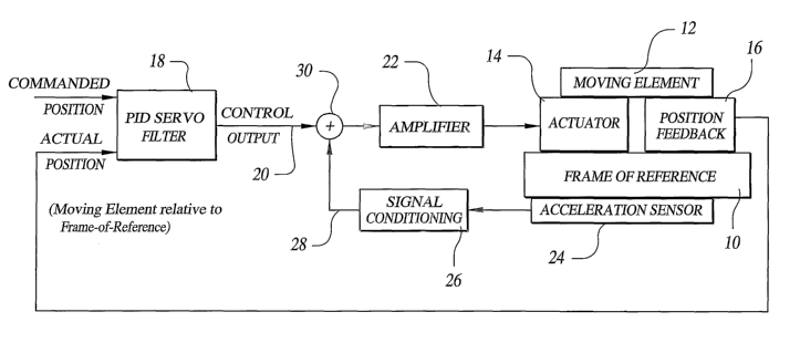
Fig. 1 is a schematic illustration of an embodiment of the invention.
Fig. 2 is a graph of following error vs. time for an embodiment of the
invention
with an acceleration signal being used.
Fig. 3 is a graph of following error vs. time for a system not using an
acceleration signal.
Description of the Preferred Embodiment
With reference first to Fig. 1, a frame of reference or base 10 may be, for
example, a granite machine base, as is well known in the art. The base may be
supported on isolation supports to minimize external disturbances. A moving
element
12 may be, for example, a substrate, work-piece, maslc, or any process
equipment
supported for motion with respect to the frame of reference 10. The moving
element 12
may move in multiple degrees of freedom, but is illustrated in Fig. 1 for a
single degree
2
CA 02522922 2005-10-13
WO 2004/092845 PCT/US2004/010723
of freedom. The moving element 12 is typically supported on the base 10 in a
low
friction manner such as with ball bearings or air bearings.
An actuator 14 is rigidly affixed to the base 10 and is arranged to apply
forces to
the moving element 12 so as to move it with respect to the base 10. A position
feedback sensor 16 responds to the position of the moving element 12 with
respect to
the base 10 and sends a position feedback signal to a Pm servo filter 18. As
those
spilled in the art will recognize, a PID servo filter is a proportional-
integral-derivative
servo controller. As is well known, the PID servo filter 18 compares a
commanded
position with the measured position to generate a control output signal 20
that provides
an input to an amplifier 22 that drives the actuator 14. As those skilled in
the art will
appreciate, a following error must exist between the desired position and the
actual
position of the moving element in order for a Pm servo controller to develop
the
necessary force, leading to a degradation in performance.
In order to reduce such following error, especially in the presence of base 10
motion, an acceleration sensor 24 is rigidly attached to the base 10. The
acceleration
sensor 24 generates an output signal which serves as an input to a signal
conditioning
element 26. As those spilled in the art will appreciate, the signal
conditioning element
26 may be merely a selected gain constant. An output signal 28 from the signal
conditioning element 26 is combined with the control output signal 20 at a
summing
junction 30. The signal 28 thus modifies the command to the amplifier 22 in
such a
way that a modified force will be applied by the actuator 14 to the moving
element 12.
The modified force is sufficient to accelerate the moving element 12 such that
the
moving element 12 "stays with" the frame of reference or base 10 thereby
reducing any
following error to be within an acceptable bound.
The present invention has been implemented on a large gantry type AC 3500
positioning platform manufactured by Danaher Corporation of Westborough, MA.
Such a machine is used in the manufacture of high precision substrates for
electronic
equipment. A typical application for this machine requires that the moving
axis be
within ~ 5 ~,m of a commanded final position before subsequent process steps
can be
conducted. For this machine, the moving axis moves in increments of 131 mm and
throughput considerations mandate that the settling criterion (~ 5 ~,m) be
achieved
within approximately 525 ms after the move has begun.
CA 02522922 2005-10-13
WO 2004/092845 PCT/US2004/010723
The accelerometer 24 used in this exemplary implementation is designated as
part number LCF-165 from Jewel Instruments, LLC, of Manchester, NH. A suitable
position feedbacp sensor 16 is a linear encoder with a resolution of 50
nm/count. The
settling criterion of ~ S~m is therefore equivalent to ~ 100 counts from the
position
sensor 16.
Experiments were conducted both with the acceleration sensor 24 in effect and
not in effect. Fig. 2 is a plot of following error versus time for a 131 mm
move with the
acceleration sensor 24 employed in the control loop. As shown, the following
error (in
counts) decreased to less than ~ 100 counts at approximately 510 ms after the
beginning of the move. Residual oscillations are evident but are witlun the
settling
tolerance. Fig. 3 is a plot of following error measured in counts as a
ftmction of time
but with the acceleration sensor 24 not being used in the control loop. Fig. 3
shows the
strong effect of base 10 rocking on the settling process. As shown, the
following error
exceeds 400 counts (20 p~m) at its first peak at about 520 ms and exceeds 250
counts
(12.5 ~.m) at its second peals at about 780 ms. Such a performance level is
unacceptable because the long delay in settling adds significant time to
customer
process steps and reduces throughput accordingly.
It should be noted that inertial sensors such as gyroscopes or inclinometers
may
be used in place of an accelerometer. It will be appreciated that when more
than one
degree of freedom is being controlled there will be inertial instruments about
multiple
axes.
It is recognized that modifications and variations of the invention disclosed
herein will be apparent to those spilled in the art and all such modifications
and
variations are included within the scope of the appended claims.
30
4