Note: Descriptions are shown in the official language in which they were submitted.
CA 02522972 2005-10-07
DOWNHOLE PUMP
Technical Field
[0001] This invention relates to pumps and, more specifically,
pumps which can be efficiently operated at significant depths. Specific
s embodiments of this invention have application in dewatering gas wells
and pumping oil from oil wells. Pumps according to the invention may
also be used in water wells.
Back round
[0002] Natural gas is collected in gas wells which intersect with
gas-bearing formations. If water in a gas well rises to a level above a
gas-bearing formation or collects in a tubing or casing, then the water
can interfere with the efficient collection of natural gas. It is therefore
necessary to provide a means to remove water from the well.
is
[0003] In the production of coal bed methane, it is necessary to
pump water from a well in order to decrease the head of water in a coal
seam to just below the top of the seam. Removal of water releases the
pressure holding the gas in the coal seam. This frees the gas so that it
2o can be extracted.
[0004] Pump jacks are often used to remove water from gas wells.
A pump jack is a device located at the surface which reciprocates a
pump rod by rotation of a crank driven by a motor. The motor rotates a
2s counter-weighted crank, thereby causing a beam to move up and down.
The beam drives a pump rod, which extends to a pump located in the
well bore at or above or below the gas bearing formation, thereby
operating the pump. Although common, pump jacks are bulky and
expensive to use. Additionally, they are prone to gas lock during
30 operation.
[0005] Soberg, Canadian patent No. 466,781 discloses a deep well
pump. A pump cylinder contains a hollow piston adapted to be
CA 02522972 2005-10-07
-2-
reciprocated by variation of the static pressure of a liquid column above
the piston. Downward movement of the hollow piston is provided by an
increase in pressure above the liquid. This drives liquid into the hollow
piston, compressing a body of gas. The pressure on the liquid above the
s piston is then decreased. The piston then rises under the influence of a
suitable spring or metal bellows positioned beneath the cylinder. This
pump requires an air chamber within the cylinder, which limits the
liquid-pumping capacity of the pump.
to [0006] Canalizo, Canadian patent No. 1,203,749 discloses a
second design for a deep well pump. This pump uses a power piston
and a production piston that are rigidly interconnected. A hydraulic
fluid acting on the power piston moves the power piston downward,
causing a production cylinder to fill with fluid. When the hydraulic
15 force on the power piston fluid is removed, both pistons are moved in
the opposite direction, either by using a power fluid of lesser density
than the production fluid, or by isolating the hydrostatic head of fluid in
the tubing from the production cylinder so that the production cylinder
is subjected to bottom hole pressure that is less than the tubing pressure
2o at the pump.
[0007] There remains a need for reliable and cost effective
apparatus and methods for pumping in deep wells.
25 Summary of the Invention
[0008] This invention provides pumps capable of operating in gas
wells and other downhole applications. The pumps are operated by
fluid pressure. In some embodiments the pumps are operated by varying
the pressure of a fluid being pumped.
CA 02522972 2005-10-07
-3-
[0009] One aspect of the invention provides pumps adapted to be
used in a tubing in a well. The pumps comprise: a piston assembly
reciprocably engaged in a cylinder assembly. The piston assembly
comprises a first piston coupled to a second piston. The second piston
has a larger cross-sectional area than the cross-sectional area of the first
piston. A pumping chamber is defined by the piston assembly and the
cylinder assembly. A first means is provided for biasing the piston
assembly in a first direction. The first means for biasing the piston
assembly in a first direction extends between the piston assembly and an
1 o anchor point located outward of the piston assembly. The piston
assembly may be moved in a second direction, which is opposite the
first direction, by increasing the pressure of a fluid in the tubing against
the first piston. The pressure may be increased by introducing a first
volume of fluid into the tubing. A second volume of fluid is expelled
1 s from the pumping chamber when the piston assembly moves in the first
direction. The second volume of fluid is larger than the first volume of
fluid. The first direction may be upward and the second direction may
be downward. The anchor point may be above the piston assembly.
20 [0010] The anchor point may be located at substantially the surface
of the well, for example, above the top of a casing of the well.
[0011] The first means for biasing the piston assembly in a first
direction may comprise an elastically-stretchable wire, which may be
2s stretchable by the length of a stroke of the piston assembly. In some
embodiments, the length of the stroke is in the range of approximately 5
feet to 15 feet. In some embodiments the elastically-stretchable wire is
at least 500 feet long. In some embodiments the first means for biasing
the piston assembly in a first direction comprises a coil spring, a
3o Belleville spring pack, or the like.
CA 02522972 2005-10-07
-4-
[0012] The pumps may also include, extending between the piston
assembly and a point inward in the well of the piston assembly, a second
means for biasing the piston assembly in the first direction. The second
means may include, for example, a Belleville spring pack, a pneumatic
s spring or a hydraulic force multiplier.
[0013] The second piston may comprise at least one one-way valve
in a path of fluid communication between the pumping chamber and a
space in the tubing which is inward of the piston assembly, the at least
one one-way valve of the second piston allows fluid to flow into the
pumping chamber. The cylinder assembly may comprise at least one
one-way valve in a path of fluid communication between the pumping
chamber and a space in the tubing which is outward of the cylinder
assembly, the at least one one-way valve of the cylinder assembly
1 s allows fluid to flow only out of the pumping chamber to the space of the
tubing which is outward of the cylinder assembly. The second piston
may comprise at least one one-way valve in a path of fluid
communication between the pumping chamber and a space in the tubing
which is inward of the cylinder assembly. The first piston may include
2o a hollow portion having at least one one-way valve in a path of fluid
communication between the pumping chamber and a space in the tubing
which is outward of the cylinder assembly, the at least one one-way
valve of the first piston allows fluid to flow only out of the pumping
chamber to the space of the tubing which is outward of the cylinder
2s assembly, the fluid being expelled from the pumping chamber through
the hollow portion.
[0014] In some embodiments, the space in the tubing which is
inward of the cylinder assembly may be below the cylinder assembly
3o and the space in the tubing which is outward of the cylinder assembly
may be above the cylinder assembly.
CA 02522972 2005-10-07
-5-
[0015] According to another aspect, the invention provides for
pumping systems comprising a pump according to the invention and
means for varying the pressure of the fluid in the tubing against the first
s piston. The means for varying the pressure of the fluid against the first
piston may include a pump or other pressure source connected to
introduce fluid into the tubing to increase the pressure against the first
piston and a control valve in fluid communication with the tubing which
may be opened to permit fluid to be removed from the tubing to
1 o decrease the pressure against the first piston. The pressure source may
comprise a pneumatic pump, a motor-driven pump, an electric pump, a
high pressure pipeline or a gas compressor, or the like. The pressure
source may be located at the surface of the well.
1 s [0016] The pumping system may be adapted for many types of
applications, including for use in gas wells, wherein gas is permitted to
flow in a well casing in the first direction, for use in dewatering coal
beds to facilitate extraction of coal bed methane, and for use in an oil
well, wherein the production fluid is pumped up the tubing.
[0017] The pumping systems may include means for preventing
fluid from passing from the tubing into the casing in the event that the
pump fails.
2s [0018] The pumping systems may include a sealing apparatus
which is slidable between a first position which is open to allow fluid to
enter the tubing from the well below the pump, and a second position
which is closed to prevent liquid from escaping from the tubing into the
well. The cylinder assembly may include a downwardly projecting
3o member that displaces the sealing apparatus downwardly to hold the
sealing apparatus in the first, open, position during normal operation of
CA 02522972 2005-10-07
-6-
the pump. The sealing apparatus may comprise a spring loaded sleeve,
a spring-loaded ball or a plunger.
[0019] The pumping systems may include a fluid reservoir in fluid
communication with the pressure source, the fluid reservoir containing
s the fluid to be introduced into the tubing by the pressure source. The
control valve may be in fluid communication with the fluid reservoir.
The fluid removed from the tubing and flowing through the control
valve may be deposited in the fluid reservoir. The fluid reservoir may
have an outlet for removing excess fluid from the fluid reservoir.
to
[0020] The pumping systems may include means for opening and
closing the control valve and means for monitoring the pressure of the
fluid in the tubing against the first piston, the means for monitoring the
pressure of the fluid in the tubing against the first piston being in
I5 communication with the means for opening and closing the control
valve, whereby the control valve is opened and closed according to the
pressure of the fluid in the tubing against the first piston. The means
for monitoring the pressure of the fluid in the tubing against the first
piston may include one or more of: means for monitoring the tension in
2o the first means for biasing the piston assembly in a first direction, means
for monitoring the cycle time of the pump, means for monitoring the
fluid discharge rate of the pump and means for monitoring the rate of
any gas flowing out of the well.
25 [0021] According to another aspect, the invention provides
pumping apparatus for use in a tubing in a well. The pumping
apparatus comprise a piston assembly reciprocably engaged within a
cylinder assembly, means for applying a force in a first direction to the
piston assembly, the means for applying a force in a first direction to the
3o piston assembly extending between the piston assembly and an anchor
point located proximal of the piston assembly, and means for causing
CA 02522972 2005-10-07
the pressure of a column of fluid within the tubing against the first
piston to vary in order to alternately apply and release a force on the
piston assembly in the first direction.
[0022] Another aspect of the invention provides a pump adapted to
be used in a tubing in a well. The pump comprises a piston assembly
reciprocably engaged in a cylinder assembly to define a pumping
chamber, an elastically-extendable member (for example, an elastically-
stretchable wire) coupled between the piston assembly and an anchor
1 o point located outward of the piston assembly, and a sealing apparatus
comprising a member which is movable between a first position which
is open to allow fluid to enter the tubing from the well below the pump,
and a second position which is closed to prevent liquid from passing
from the tubing into the well below the pump. The cylinder assembly is
1 s disposed to displace the sealing apparatus downwardly to hold the
sealing apparatus in the first position during normal operation of the
pump. A tension in the elastically-extendable member is sufficient to lift
the cylinder assembly away from the sealing apparatus in the event that
a pressure of liquid in the tubing against an outer side of the cylinder
2o assembly is less than a threshold amount.
[0023] Another aspect of the invention provides a pump for
pumping fluid from a well. The pump comprises a cylinder assembly
disposed within a bore of the well. The bore may be, for example, a
2s bore of a section of tubing within the well. The cylinder assembly
comprises a bulkhead extending across the bore and has a piston
assembly mounted for reciprocation in the cylinder assembly. The piston
assembly comprises a first piston slidably and sealingly disposed within
a bore of the cylinder assembly and a second piston coupled to the first
3o piston and projecting through an aperture in the bulkhead. The piston
assembly defines a variable-volume pumping chamber between the first
CA 02522972 2005-10-07
_ g _
piston and the bulkhead. A first one-way valve is disposed to permit
fluid to flow from the pumping chamber to a space on an opposite side
of the bulkhead from the pumping chamber. A second one-way valve is
disposed to permit fluid to flow into the pumping chamber from a space
s on an opposite side of the first piston from the pumping chamber. An
elastically-extendable member is coupled between the piston assembly
and an anchor point located outward relative to the bulkhead.
[0024] According to yet another aspect, the invention provides
1 o methods for pumping fluid from a well. The methods include providing
a pump according to the invention in a well, varying the pressure of a
fluid in the tubing against the first piston, wherein increasing the
pressure of fluid against the first piston allows the piston assembly to
move in a second direction which is opposite the first direction, thereby
1 s allowing fluid to enter the pumping chamber, and wherein reducing the
pressure of the fluid against the first piston causes the piston assembly to
move in the first direction thereby expelling fluid from the pumping
chamber, wherein the pressure of the fluid against the first piston is
increased by introducing a first volume of fluid into the tubing, and a
2o second volume of fluid is expelled from the pumping chamber when the
piston assembly moves in the first direction, the second volume of fluid
being larger than the first volume of fluid.
[0025] The methods may include monitoring the pressure of the
2s fluid in the tubing against the first piston and adjusting the pressure
against the first piston in order to vary the pressure of the fluid in the
tubing against the first piston. Monitoring the pressure of the fluid in
the tubing against the first piston may include monitoring one or more
of: the tension in the first means for biasing the piston assembly in the
3o first direction, the cycle time of the pump, the fluid discharge rate of
the
pump and the rate of any gas flowing out of the well.
CA 02522972 2005-10-07
-9-
[0026] The pressure of the fluid in the tubing against the first
piston may be decreased by opening a control valve in fluid
communication with the tubing thereby permitting fluid to be removed
s from the tubing. The first means for biasing the piston assembly in the
first direction may comprise an elastically-stretchable wire, and the
methods may also include monitoring and adjusting the tension and
length of a wire.
1 o [0027] Another aspect of the invention provides a method for
pumping fluid from a well. The method comprises providing, in a
tubing in a well, a pump comprising a piston assembly reciprocably
engaged in a cylinder assembly; providing an elongated elastically-
extendable member extending from the piston assembly to an anchor
1 s point located outward of the piston assembly; holding the cylinder
assembly down in the tubing by a weight of liquid above the cylinder
assembly in the tubing; and, reciprocating the piston assembly by
pulling periodically on an upward end of the elastically-extendable
member.
[0028] Further aspects of the invention and features of
embodiments of the invention are set out below.
Brief Description of Drawings
2s [0029] In drawings which illustrate non-limiting embodiments of
the invention:
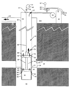
[0030] Figure 1 is a schematic diagram of a pump in a gas well
representing one embodiment of this invention at the top of the pumping
cycle .
3o [0031] Figure 2 is a schematic diagram of the pump of Figure 1 in
a gas well at the bottom of the pumping cycle.
CA 02522972 2005-10-07
- 10-
[0032] Figure 3 is a schematic diagram illustrating how a spring
loaded sleeve functions if the downhole pump fails or leaks.
[0033] Figure 4 is a schematic illustration of pump in a gas well
according to a second embodiment of the invention.
s [0034] Figure 5 is a schematic diagram of a downhole pump
according to a third embodiment of this invention. This embodiment
includes an auxiliary spring positioned below the downhole pump.
[0035] Figure 6 is a schematic diagram of a pump representing a
fourth embodiment of the invention wherein the pump is configured to
1 o pump fluid down into the well from a higher elevation within the well.
[0036] Figure 7 is a schematic diagram of a pump according to a
fifth embodiment of this invention. In this embodiment, the pump is
configured to allow pumping through separate discharge and suction
pipes without a fluid reservoir.
1 s [0037] Figure 8 is a schematic diagram of a downhole pump being
used to pump oil up the tubing of an oil well.
Description
[0038] Throughout the following description, specific details are
2o set forth in order to provide a more thorough understanding of the
invention. However, the invention may be practiced without these
particulars. In other instances, well known elements have not been
shown or described in detail to avoid unnecessarily obscuring the
invention. Accordingly, the specification and drawings are to be
25 regarded in an illustrative, rather than a restrictive, sense.
[0039] Figure 1 shows a gas well 22. Well 22 is of sufficient
depth to reach a gas-producing stratum, represented in the figures by a
gas zone 26, or a seam of coal. Well 22 may be deep, for example 500
3o feet to 10,000 feet or more in some instances. A typical depth for a
well 22 in which this invention can be most effectively applied is, for
CA 02522972 2005-10-07
-11-
example, 6,000 feet. The term "deep well" is used herein to mean a
well having a depth of at least 500 feet. The break lines shown in the
drawings indicate that the depths of the wells shown in the drawings are
not to scale.
s
[0040] Well 22 includes a casing 24, within which is contained a
tubing 20. Gas from gas zone 26 enters casing 24 through perforations
28. Water and/or hydrocarbon liquids 30 also enter casing 24 through
perforations 28 along with gas 26 as a mixture in mist form. As used
1 o herein, the term water refers to both water and/or hydrocarbon liquids,
which may be for example condensate or oil. Once inside casing 24,
gas 26 tends to separate and flow upwards, while water 30 remains
behind unless well formation 22 has enough pressure to induce sufficient
velocity to carry the liquids up casing 24 with the gas, termed the
I5 critical lift rate. Water 30 tends to rise within casing 24 to a level 31.
The flow of gas 26 up casing 24 will be inhibited whenever the water
level is above gas zone 26. If it is desired that the gas 26 flow up
casing 24 when well 22 lacks sufficient pressure to achieve the critical
lift rate, it is therefore necessary to provide a means for pumping water
20 30 up to the surface 22a of the well and out of well 22 at a sufficient
rate to maintain water level 31 in casing 24 below the level of
perforations 28.
[0041] A pump 10 pumps water 30 up tubing 20, thereby allowing
25 gas from gas zone 26 to flow freely up casing 24 as indicated by arrow
27. Gas is collected at the top of casing 24, as indicated by arrow 29.
Pump 10 has a piston assembly 34 which is reciprocably engaged in a
cylinder assembly 32. Cylinder assembly 32 is positioned at an
appropriate depth within well 22 to enable it to pump water 30 upward
3o within tubing 20, thereby maintaining water level 31 below the level of
perforations 28. Cylinder assembly 32 has a seal 35 positioned
CA 02522972 2005-10-07
-12-
between cylinder assembly 32 and tubing 20 to prevent the flow of
liquid past cylinder assembly 32. Cylinder assembly 32 may comprise,
for example, a chrome cylinder with finite or no-gap TeflonTM piston
rings. In the illustrated embodiment, cylinder assembly 32 is held in
s position by the weight of the column of fluid 56 above cylinder
assembly 32 in tubing 20.
[0042] Cylinder assembly 32 and piston assembly 34 define a
pumping chamber 44. Pumping chamber 44 may also be provided by
1 o use of a bellows or diaphragm, but is preferably provided by cylinder
assembly 32 and piston assembly 34 as described herein. Reciprocation
of piston assembly 34 within cylinder assembly 32 causes pumping
chamber 44 to expand and contract. Cylinder assembly 32 has at least
one one-way discharge valve assembly 36 in a path of fluid
1 s communication extending between a space 37, which is located in tubing
20 above cylinder assembly 32, and pumping chamber 44. Contraction
of pumping chamber 44 thus forces water from within pumping chamber
44 into space 37. Any suitable mechanism permitting liquid to flow
only in the direction from pumping chamber 44 to space 37 may be
2o used for discharge valve assembly 36.
[0043] Piston assembly 34 comprises a first piston 38 coupled to a
second piston 40. Piston 38 and piston 40 may be integral with one
another (i.e. piston assembly 34 may be a single integrally formed part)
2s and could alternatively be separate elements which are coupled to one
another, directly or indirectly, by any suitable means. Second piston 40
has a larger cross-sectional area than first piston 38. In the illustrated
embodiment, pistons 38 and 40 (and tubing 20) each have a circular
cross-section. Second piston 40 thus has a larger diameter than first
3o piston 38 and, for convenience, the terms "small-diameter piston 38"
and "large-diameter piston 40" are used herein. However, it will be
CA 02522972 2005-10-07
-13-
appreciated that it is not necessary for pistons 38 and 40 and tubing 20
to have circular cross-sections. Other cross-sectional profiles are
possible and within the scope of this invention.
[0044] The relative sizes of small-diameter piston 38 and large-
diameter piston 40 are important. Sizing the cross-sectional areas
correctly minimizes the pressure differential required to cycle pump 10.
Further, if the cross-sectional area of small-diameter piston 38 is too
small, the hydraulic force required to move it may exceed the tubing
to limit. The cross-sectional areas of small-diameter piston 38 may for
example be sized to operate at a maximum of 5000 PSI; however, use of
tubing 20 with a higher pressure rating may allow use of a small-
diameter piston 38 sized to operate at higher pressures. The differential
pressure required for the stroke of downhole pump 10 varies with the
relative sizes of small-diameter piston 38 and large-diameter piston 40,
and seal friction. Downhole pump 10 may, for example, cycle every 15
minutes at approximately 800 PSI Differential Pressure to move 1 BBL
of fluid per day.
[0045] Piston assembly 34 has at least one one-way inlet valve
assembly 42, which is in a path of fluid communication extending
between a space 39 located below piston assembly 34 and pumping
chamber 44. In the illustrated embodiment, inlet valve assembly 42 is
located on large-diameter piston 40. Inlet valve assembly 42 could also
be located on the side of cylinder assembly 32. Any suitable mechanism
permitting liquid to flow only in the direction from space 39 to pumping
chamber 44 may be used for inlet valve assembly 42.
[0046] The illustrated embodiment shows a vertically oriented
3o well, and thus space 37 has been described herein as being "above"
cylinder assembly 32 and space 39 has been described as being "below"
CA 02522972 2005-10-07
- 14-
piston assembly 34. These and other similar directional terms are used
as a matter of convenience and should not be interpreted narrowly. It
is to be understood that the present invention is not restricted to
apparatuses and methods involving, or for use in, only vertically-
s oriented wells, but also includes apparatuses and methods involving or
for use in wells of other orientations such as angled or horizontal
orientations .
[0047] As used herein (including in the claims) the words
"outward" and "inward" refer to the relative positions of two elements
or spaces in relation to the surface 22a of the well 22. That is, a first
element (or space) is "outward" of a second element (or space) where
the first element (or space) is nearer to surface 22a than the second
element (or space). For example, space 37 is outward of cylinder
assembly 32 because it is nearer to surface 22a than cylinder assembly
32. Similarly, one element (or space) is "inward" of another element
(or space) where it is farther from surface 22a than the other element
(or space). For example, space 39 is inward of piston assembly 34 as it
is farther from surface 22a of the well than piston assembly 34.
[0048] Pump 10 includes a first means for biasing piston assembly
34 in a first direction. In the illustrated embodiment, the first direction
is upward as the well is vertical, but as noted, the well need not be
vertical and thus the first direction can, but need not necessarily be,
2s upward. The first means for biasing piston assembly in a first direction
comprises a member extending between piston assembly 34 and an
anchor point 49 located outward of the piston assembly. In the
illustrated embodiment, anchor point is located above the height reached
by the top of piston assembly 34 at the top of the pumping cycle. In
3o some embodiments, anchor point 49 is located substantially at the
surface of well 22. "Substantially at the surface of well 22" means
CA 02522972 2005-10-07
-15-
being positioned at or above the surface or within well 22 at a depth no
greater than 10 % of the total depth of well 22. In some embodiments,
anchor point 49 is located above the top of casing 24.
[0049] In the illustrated embodiment, the first means for biasing
piston assembly 34 in the first direction comprises an extension spring,
which may be a spring wire 46. Spring wire 46 applies upward force to
piston assembly 34. Any suitable elastically-stretchable, or otherwise
elastically-extendable, material may be used for spring wire 46.
1 o Spring wire 46 may preferably be made from, for example, chrome
silicon wire at 3/8 inch diameter or 3/16 inch stainless steel slickline,
which can be elastically stretched by, for example, approximately 1
metre per 1000 metres of length. Spring wire 46 may also comprise
nylon rope or material like a heavy guitar string. Spring wire 46 should
be capable of elastically stretching by the length of the pump stroke. In
some embodiments of this invention the pump stroke has a length in the
range of about 5 feet to 15 feet.
[0050] In the illustrated embodiment, spring wire 46 is coupled to
2o the upper end of small-diameter piston 38. Spring wire 46 is also
coupled to anchor point 49. In the illustrated embodiment, an adjusting
winch 50 is located at anchor point 49, which is located above the top of
casing 24. Adjusting winch 50 is used to regulate the position of
downhole pump 10 in well 22, and to regulate the tension in spring wire
46. A seal 51 seals between connecting wire 48 and tubing 20 to
prevent fluid leaking out when pressure is applied to column of fluid 56.
[0051] A tension indicator may be used in conjunction with
downhole pump 10 to indicate that an appropriate level of tension is
3o being applied to spring wire 46. The tension indicator is preferably
located at the surface 22a to facilitate monitoring the tension in spring
CA 02522972 2005-10-07
-16-
wire 46, and it may be connected to adjusting winch 50. In the
embodiment illustrated in Figure 1, a weight indicator 52 functions as a
tension indicator. Weight indicator 52 may comprise, for example, a
series of three pulleys positioned so as to cause a small bend in the wire,
with a weight indicator connected to measure a force exerted by the
wire on the central pulley.
(0052] A pressure source 54 located at the surface 22a of well 22
is used in combination with a control valve 58 to alternately apply
to pressure to and release pressure from a column of fluid 56 in tubing 20.
Pressure source 54 may comprise, for example a high-pressure pipeline,
compressor discharge gas, an electrical pump, or a motor-driven pump.
Pressure source 54 is preferably a pneumatic pump.
[0053] Control valve 58 is opened and closed to regulate the
pumping cycle by a control mechanism 57. Control mechanism 57
may, for example, comprise a computer or programmable controller
which operates an actuator coupled to operate control valve 58. Control
mechanism 57 could for example operate by sensing the tension in
2o spring wire 46. Control mechanism 57 could also monitor the cycle
time, gas flow rate, or the discharge rate of downhole pump 10 to
determine if the pumping rate is too high, too low, or if downhole pump
10 has failed.
[0054] The column of fluid 56 may be initially provided by
pumping fluid into tubing 20 from the surface with no tension in spring
wire 46. The fluid used in column of fluid 56 preferably has the same
specific gravity as the production fluid of well 22. Column of fluid 56
may be liquid, gas, or a combination of liquid and gas. Column of fluid
3o 56 functions as the power transmitting fluid to transmit the pressure
generated by pressure source 54 to small-diameter piston 38. The
CA 02522972 2005-10-07
- 17-
discharge fluid from downhole pump 10 therefore serves as the power
transmitting fluid to operate downhole pump 10.
[0055] Spring wire 46 is adjusted to the appropriate tension by
gradually increasing the tension until piston assembly 34 moves
upwards. At this point, there is no increase in the tension in spring wire
46 as piston assembly 34 moves upward. Once piston assembly 34 is at
the top of its stroke, tension begins to increase again, and downhole
pump 10 is prepared for use. The spring tension in spring wire 46 is
1 o preferably high enough to move piston assembly 34 to the top of its
stroke against the pressure exerted on small-diameter piston 38 by the
weight of column of fluid 56, but not significantly.
[0056] To operate downhole pump 10, pressure source 54 pumps
1 s fluid into the column of fluid 56. When control valve 58 is in the closed
position, pressurized fluid, which may be liquid or gas, from pressure
source 54 enters the column of fluid 56 as indicated by arrow 59. This
increases the pressure in column of fluid 56. Release of the pressure on
column of fluid 56 is achieved by opening control valve 58 to allow
2o fluid to enter a fluid reservoir 60. Pressure source 54 may continue to
pump when control valve 58 is open, or its operation may be stopped.
[0057] Figure 1 shows downhole pump 10 at the top of its
pumping cycle. To operate downhole pump 10, column of fluid 56 is
2s pressurized by operating pressure source 54 while control valve 58 is
closed. The pressure in column of fluid 56 increases upon the
introduction of fluid into tubing 20 by pressure source 54. This
increases the net force acting on small-diameter piston 38, causing
piston assembly 34 to move in a second direction, as indicated by arrow
30 61. The second direction is opposite the first direction. In the
illustrated embodiment, with a vertical well, the second direction is
CA 02522972 2005-10-07
-18-
downward. Again, the invention can be practiced in wells having
orientations other than vertical, meaning that the second direction may,
but need not necessarily, be downward.
s [0058] Advantageously, in some embodiments of the invention,
pumping chamber 44 is reduced to substantially zero volume when
piston assembly 32 is at the top of its stroke. Providing such zero
clearance between the top of larger diameter piston 40 and cylinder
assembly 32 permits gas to be effectively expelled from pumping
1 o chamber 44 and reduces the possibility that trapped gases could cause a
"gas lock" .
[0059] Pressure in column of fluid 56 applies a downward force to
the top of small-diameter piston 38. As piston assembly 34 moves
~ 5 downward relative to cylinder assembly 32, water 30 enters pumping
chamber 44 via inlet valve assembly 42, as indicated by arrows 63.
[0060] Figure 2 shows downhole pump 10 at the bottom of its
pumping cycle. To return downhole pump 10 to the top of its cycle,
2o control valve 58 releases the pressure in column of fluid 56. Control
valve 58 is open in Figure 2. The release of pressure within column of
fluid 56 reduces the downward force on small-diameter piston 38. This
permits spring wire 46 to move piston assembly 34 in an upward
direction relative to cylinder assembly 32, as shown by arrow 73. The
25 resulting compression of pumping chamber 44 causes the fluid contained
therein to be expelled through outlet valve assembly 36 into space 37, as
indicated by arrows 75. Downhole pump 10 is thereby returned to the
top of its pumping cycle. As downhole pump 10 returns to the top of
its cycle, fluid from the column of fluid 56 enters a fluid reservoir 60
3o as indicated by arrows 67 and 69. A discharge outlet 65 removes
excess fluid from the system as shown by arrow 71.
CA 02522972 2005-10-07
- 19-
[0061] It will be appreciated that there will be a net flow of fluid
out of tube 20 in the pumping cycle of pump 10. This results from the
difference in cross-sectional areas between small-diameter piston 38 and
s large-diameter piston 40. In other words, the volume of fluid expelled
from the tube 20 during the up stroke of pump 10 will exceed the
volume of fluid introduced into tube 20 during the down stroke of pump
10. This can be appreciated with reference to Figures 1 and 2.
[0062] In particular, Figure 1 illustrates the pump 10 at the top of
the pumping cycle and Figure 2 illustrates the pump 10 at the bottom of
the pumping cycle. A first volume of fluid is introduced into tube 20
(via pressure source 54) during the down stroke of pump 10 as
explained above. The first volume of fluid is equivalent to the volume
1 s of the portion of the small-diameter piston 38 which is displaced
downwardly during the downward movement of the piston assembly 34
during the down stroke (plus a small amount to compensate for any
expansion of tubing 20 and for compression of any gas entrained in
column of fluid 56 resulting from the increased pressure resulting from
2o the introduction of fluid into tube 20) . This can be seen by comparing
how much of the small-diameter piston 38 is above the top of cylinder
assembly 32 at the top of the pumping cycle, as shown in Figure 1,
relative to the bottom of the pumping cycle, as shown in Figure 2. On
the other hand, a second volume of fluid is expelled from tube 20 during
2s the up stroke. The second volume of fluid is equivalent to the volume
of the expanded pump chamber 44 shown in Figure 2. This volume of
fluid is expelled through one-way discharge valve 36 during the up
stroke, causing an equivalent volume of fluid to be expelled from
column of fluid 56 in tube 20 and into reservoir 60 and/or discharged
3o from the system through discharge outlet 65, as explained above. Since
the cross-sectional area of large-diameter piston 40 is greater than the
CA 02522972 2005-10-07
-20-
cross-sectional area of small-diameter piston 38, the second volume of
fluid (i.e. that which is expelled from tube 20 during the up stroke) is
greater than the first volume of fluid (i.e. that which is introduced into
tube 20 during the down stroke), resulting in a net flow of fluid out of
tube 20 during each pumping cycle of pump 10.
[0063] Downhole pump 10 may also include a spring-loaded
sleeve 68, which is a device known to those skilled in the art. Spring-
loaded sleeve 68 is sealed in tubing 20 by seals 88. Spring-loaded
1 o sleeve 68 is displaced downwardly when downhole pump 10 is located
at the appropriate depth within gas well 22. The weight of the column
of fluid 56 holds downhole pump 10 in position. A member 66
projecting downward from cylinder assembly 32 pushes sleeve 68
downward into its open position when downhole pump 10 is at the
I5 operating depth. This creates an opening 53 which allows water to
enter tubing 20. If downhole pump 10 fails or leaks, water from
column of fluid 56 will leak down past cylinder assembly 32, thereby
reducing the force applied to downhole pump 10 by column of fluid 56.
20 [0064] Eventually, if the leaking continues, the upward force
applied by spring wire 46 will pull both piston assembly 34 and cylinder
assembly 32 up within tubing 20. This result is shown in Figure 3. As
a result of the upward movement of downhole pump 10, spring-loaded
sleeve 68 is no longer displaced downwardly by cylinder assembly 32.
25 This results in the elimination of opening 53, and closes off the lower
end of tubing 20. Sleeve 68 thereby prevents fluid from leaking from
within tubing 20 into casing 24. The function of spring-loaded sleeve
68 may also be performed by a spring-loaded ball or a plunger, which
are devices known to those skilled in the art. Any other similar device
3o wherein a sealing mechanism is displaced by downhole pump 10 to
allow fluid to enter tubing 20, but which seals if downhole pump 10
CA 02522972 2005-10-07
-21 -
moves upward within tubing 20, may also be used in place of spring-
loaded sleeve 68. A check valve, also a device known to those skilled
in the art, should not be used in place of spring-loaded sleeve 68
because there is always reverse flow at the suction side of downhole
pump 10. The presence of continuous reverse flow allows the use of a
good suction screen 55 positioned at the fluid intake of downhole pump
10, which is constantly being purged by the reverse flow.
[0065] A downhole pump l0A representing another embodiment of
1 o this invention is shown at the bottom of its pumping cycle in Figure 4.
Downhole pump l0A is similar to downhole pump 10, except that the
upward bias is provided by a coil spring 46A. Coil spring 46A could be
replaced by or augmented with a Belleville spring pack or any other
elastically-extendable unit providing a sufficient degree of extension.
1 s Coil spring 46A is coupled via a connecting wire 48 to anchor point 49.
Coil spring 46A is preferably located near the top of piston assembly
34A in order to minimize the movement of connecting wire 48.
[0066] The first means to bias the piston assembly in the first
2o direction may include a spring to provide additional upward force on
piston assembly 34A. In the embodiment illustrated in Figure 4, the
spring comprises a Belleville spring pack 62. A coil spring may
alternatively be used alone or in combination with a Belleville spring
pack. Belleville spring pack 62 is coupled to both cylinder assembly
25 32A and the spring wire 46A. Belleville spring pack 62 may be coupled
to spring wire 46A by a clamp 47 or other suitable mechanism.
Belleville spring pack 62 is compressed on the downstroke of the pump,
and functions to pull a pump plunger 70 upward upon the release of
hydrostatic pressure within tubing 20 by augmenting the force provided
3o by spring wire 46A.
CA 02522972 2005-10-07
-22-
[0067] In downhole pump 10A, small-diameter piston 38 has been
replaced by a hollow pump plunger 70. Pump plunger 70 is hollow so
as to allow fluid to flow through it. Pump plunger 70 includes at least
one one-way discharge valve 72 in a path of fluid communication
s between space 37 and pumping chamber 44. Water exits pumping
chamber 44 through discharge valve 72, thereby passing through pump
plunger 70. Any suitable valve mechanism allowing only the one-way
flow of water from pumping chamber 44 to space 37 may be used for
discharge valve 72.
[0068] The operation of downhole pump l0A is essentially as
described above. Upon pressure source 54 pressurizing column of fluid
56, a downward force is applied to pump plunger 70. This forces piston
assembly 34A downward, causing water to enter pumping chamber 44
1 s through inlet valve assembly 42 in the large-diameter piston 40. At the
bottom of the stroke, pressure in column of fluid 56 is released by
control valve 58, allowing coil spring 46A and Belleville spring pack 62
to pull piston assembly 34A upward. When large-diameter piston 40
moves upward within cylinder assembly 32A, water within pumping
2o chamber 44 is forced through discharge valve 72 into space 37, as
indicated by arrow 73. Downhole pump l0A is thereby returned to the
top of the pumping cycle.
[0069] A pump representing another embodiment of this invention
2s is shown as downhole pump lOB in Figure 5. In this embodiment, a
second means for biasing the piston assembly 34 in the first direction is
included. The second means for biasing the piston assembly in the first
direction extends between the piston assembly 34 and a point inward of
the piston assembly. In the illustrated embodiment, the second means
3o comprises spring 90, which is positioned below piston assembly 34, and
provides additional upward bias beyond that produced by spring wire
CA 02522972 2005-10-07
- 23 -
46. Spring 90 is held in position by a support apparatus 94, which is
anchored within tubing 20 by a sealing mechanism 92. Spring 90 may
for example comprise a Belleville spring pack, a pneumatic spring or a
hydraulic force multiplier, or the like.
S
[0070] As will be apparent to those skilled in the art in light of the
foregoing disclosure, many alterations and modifications are possible in
the practice of this invention without departing from the spirit or scope
thereof. Possible alterations and modifications include, without
limitation:
~ The features of downhole pumps 10, 10A, and lOB may be
combined in combinations other than those expressly
described above, or used singly. For example, a pump
substantially similar to downhole pump 10 could utilize a
1 s coil spring 46A and connecting wire 48 in place of spring
wire 46, but be in all other respects identical to downhole
pump 10.
~ A downhole pump could be made to pump in a reverse
direction. Figure 6 shows a downhole pump lOC which
2o has a basic structure substantially similar to that of
downhole pump 10. However, at least one one-way inlet
valve assembly 36C is located in cylinder assembly 32C in
a path of fluid communication between pumping chamber
44 and a space 33 located in casing 24 adjacent to cylinder
2s assembly 32C. A locking seal 45 ensures liquid is not
forced upward into tubing 20 upon compression of pumping
chamber 44. A standard wire line locking procedure may
be used to hold cylinder assembly 32C at the correct
position within well 22. Inlet valve assembly 36C allows
3o fluid to enter pumping chamber 44 from space 33 when
pumping chamber 44 is expanded by the release of pressure
CA 02522972 2005-10-07
-24-
in column of fluid 56 and by the upward force provided by
spring wire 46. A hole 41 in tubing 20 allows fluid to flow
from casing 24 into tubing 20. A block 43 separates the
fluid in casing 24 above the level of downhole pump 10
s from the fluid in casing 24 below the level of downhole
pump 10. At least one one-way outlet valve assembly 42C
is located in cylinder assembly 32C, in a path of fluid
communication between space 39 and pumping chamber
44. Outlet valve assembly 42C allows fluid to be expelled
1 o from pumping chamber 44 downward into gas well 22 upon
the application of pressure to column of fluid 56 by
pressure source 54.
~ The downhole pump could utilize separate inlet and
discharge pipes with no fluid reservoir. Figure 7 shows a
1 s downhole pump l OD in which an inlet pipe 80 is used to
supply fluid to pressure source 54 in order to pressurize
column of fluid 56. A separate discharge pipe 82 contains
control valve 58, and directly discharges fluid from the
column upon the release of pressure by the control valve
20 58.
~ A downhole pump according to the invention may also be
used to pump production fluid up the tubing of an oil or gas
well. Figure 8 shows downhole pump 10 being used to
pump oil from oil layer 25 to the surface. Oil from oil
2s layer 25 enters casing 24 through perforations 28, and is
pumped up tubing 20 in the same manner as previously
described for water. Column of fluid 56 comprises the
production fluid itself. Oil 25 is forced up tubing 20 by the
operation of downhole pump 10, as indicated by arrow 67.
3o Oil 25 is collected through tube 65, as indicated by arrows
69 and 71.
CA 02522972 2005-10-07
- 25 -
~ A downhole pump as described herein could be operated by
pulling wire 46 up and down in addition to, or instead of,
varying the pressure of fluid in column 56. Wire 46 may
be moved up and down using any suitable mechanism at the
surface of the well. For example, a drum of winch 50
could be driven by an electric motor which is operated by a
suitable controller to alternately take in and let out wire 46.
Other mechanisms such as a long stroke hydraulic piston or
other linear actuator could be connected to alternately take
1 o in and let out an upper end of wire 46.
Accordingly, the scope of the invention is to be construed in accordance
with the substance defined by the following claims.