Note: Descriptions are shown in the official language in which they were submitted.
CA 02523189 2005-10-21
WO 2004/093652 PCT/US2004/012189
SYSTEM AND METHOD FOR SYNTHESIS OF MOLECULAR IMAGING
PROBES INCLUDING FDG
Inventors: Charles Russell Buchanan
Henry C. Padgett
Thomas Lee Collier
Jospeh C. Matteo
Charles William Alvord
CROSS-REFERENCE TO RELATED APPLICATIONS
This non-provisional patent application claims the benefit of U.S.
Provisional Application No. 60/464,424 filed April 22, 2003
STATEMENT REGARDING FEDERALLY SPONSORED RESEARCH OR
DEVELOPMENT
Not Applicable
BACKGROUND OF THE INVENTION
1. Field of the Invention.
The invention relates to the use of microfluidic devices and methods for
chemical synthesis, particularly the use of microfluidic devices and methods
for
the synthesis of positron-emitter labeled PET molecular imaging probes.
2. Description of the Related Art.
Positron Emission Tomography (PET) is a molecular imaging technology
that is increasingly used for detection of disease. PET imaging systems create
images based on the distribution of positron-emitting isotopes in the tissue
of a
patient. The isotopes are typically administered to a patient by injection of
probe
molecules that comprise a positron-emitting isotope, such as F-18, C-11, N-13,
or
O-15, covalently attached to a molecule that is readily metabolized or
localized in
the body (e.g., glucose) or that chemically binds to receptor sites within the
body.
In some cases, the isotope is administered to the patient as an ionic solution
or by
-1-
CA 02523189 2005-10-21
WO 2004/093652 PCT/US2004/012189
inhalation. One of the most widely used positron-emitter labeled PET molecular
imaging probes is 2-deoxy-2-[1$F] fluoro-D-glucose ([1gF]FDG).
Since the inception of PET imaging in the late 1970's, PET radiochemical
synthesis systems have used standard bench-top synthesis techniques, multi-
milligram and mufti-milliliter quantities of reagents, and mufti-gram
quantities of
purification media, along with macro-scale reaction vessels and relatively
large
valve-and-tubing processing hardware.
The specific activity ofthe labeled molecular imaging probe is particularly
sensitive to the relatively large scale of known synthesis processes. The
specific
activity of an isotope or molecular imaging probe is the amount of
radioactivity
relative to the mass, often given in Curielmole (or Becquerellmole). The mass
consists of all isotopic forms of the radioactive label. The addition of a
stable
isotope along with the radioactive isotope will result in a dilution or
lowering of
the specific activity. Examples of lowered specific activity are the dilution
of C-11
with stable C-12, or the addition of stable F-19 to F-18.
The maximum specific activity for fluorine-18 is 1,710 Cil~.mol, and for
carbon-11 it is 9,240 Ci/~.mol. [18F] Fluoride ion produced by proton
bombardment of a metal target filled with [180] water in a cyclotron typically
has a
specific activity of about 50-100 Cilpmol. This represents up to a 40 to 1
dilution
with stable fluorine-19 that is present in the [1g0] water, and released from
the
metal target body and polymeric valves and tubing in the target delivery
system.
In general, 1gF-labeled molecular imaging probes prepared from [18F] fluoride
ion
have a specific activity of about 2-5 Ci/pmol after coupling the ion to a
probe
molecule, which means that the radiochemical synthesis process results in
another
25 to 1 dilution with stable fluorine-19. Fluoride ion delivered from the
cyclotron
target will typically contain 0.2-0.4 ~.g (10-20 ~.mol) stable [19F] fluoride
ion along
with the radioactive [1$F] fluoride ion. If the activity delivered is 1.0 Ci,
the [18F]
fluoride ion mass will be about 9.0 ng or 0.5 nmol. The same issues arise when
using carbon-11 or other radioactive isotopes because the prior art
radiochemical
synthesis processes are the major source of unwanted carbon-12 or other stable
isotopes.
-2-
CA 02523189 2005-10-21
WO 2004/093652 PCT/US2004/012189
U. S. Patent No. 4,794,178, which is incorporated by reference herein in its
entirety, discloses a process for producing 18F labeled organic compounds by
nucleophilic substitution.
There is a need in the art of radiochemical synthesis for devices and
methods that produce radiochemicals, such as positron-emitting PET molecular
imaging probes, exhibiting faster synthesis times and higher synthesis yields.
SUNWARY OF THE INVENTION
The present invention provides a method and apparatus for preparation of
radiochemicals, such as PET molecular imaging probes, wherein the reaction
step
or steps that couple the radioactive isptope to an organic or inorganic
compound to
form a positron-emitting molecular imaging probe are performed in a
microfluidic
environment (i.e., a micro reactor). The reactions) to form the radiolabeled
r~nolecular imaging probe can utilize gaseous or liquid reagents in a
liquid/liquid
phase, liquid/gas phase or gas/gas phase reaction. The use of microfluidics
and
micro reactor technology for the radiochemical synthesis of labeled molecular
imaging probes is advantageous because it matches the scale of the synthesis
equipment and techniques to that of the radioactive labeling reagents, thereby
promoting faster synthesis times, and higher synthesis yields. These systems
are
small, simple, reliable, microfluidics-based radiochemical synthesis systems,
In one aspect, the invention provides a method for synthesizing a
radiochemical in a microfluidic environment, the method comprising: i)
providing
a micro reactor comprising a first inlet port, a second inlet port, an outlet
port, and
at least one microchannel in fluid communication with the first and second
inlet
ports and the outlet port; ii) introducing a liquid reactive precursor
dissolved in a
polar aprotic solvent into the first inlet port of the micro reactor, the
reactive
precursor adapted for reaction with a radioactive isotope to form a
radiochemical;
iii) introducing a solution comprising a radioactive isotope dissolved in a
polar aprotic solvent into the second inlet port of the micro reactor; iv)
contacting
the reactive precursor with the isotope-containing solution in the
microchannel o~
the micro reactor; v) reacting the reactive precursor with the isotope-
containing
solution as the reactive precursor and isotope-containing solution flow
through the
microchannel of the micro reactor, the reacting step resulting in formation of
a
-3-
CA 02523189 2005-10-21
WO 2004/093652 PCT/US2004/012189
radiochemical, wherein said reacting step is conducted at a temperature above
the
boiling point of the polar aprotic solvent at 1 atm (e.g., about 85 to about
100°C)
and at a pressure sufficient to maintain the polar aprotic solvent in liquid
form
{e.g., about 2 to about 400 bar); and vi) collecting an effluent stream
comprising
the radiochemical from the outlet port of the micro reactor.
In another embodiment, the method of the invention includes i) providing a
micro reactor comprising a first inlet port, a second inlet port, an outlet
port, and at
least one microchannel in fluid communication with the first and second inlet
ports
and the outlet port; ii) providing a precursor solution and introducing the
precursor
solution into the first inlet port of the micro reactor, wherein the precursor
solution
comprises a reactive precursor adapted for reaction with a radioactive isotope
and
is dissolved in an organic solvent; iii) providing an radioactive solution and
introducing the radioactive solution into the second inlet port of the micro
reactor,
wherein the radioactive solution comprises a radioactive isotope dissolved in
an
organic solvent; and iv) uniting the precursor solution with the radioactive
solution
in the at least one microchannel of the micro reactor enabling the reactive
precursor to react with the radioactive isotope as the precursor solution and
radioactive solution flow in the microchannel to form a radiochemical in
solution.
Preferably, the radioactive isotope and reactive precursor are dissolved in a
polar aprotic solvent and moved through the micro reactor using at least one
syringe or other suitable pump. The reactive precursor and isotope-containing
solution are preferably heated during the reacting step. In one embodiment,
the
micro reactor comprises a first microchannel segment in fluid communication
with
the first inlet of the micro reactor, a second microchannel segment in fluid
communication with the second inlet of the micro reactor, and a third
microchannel
segment in fluid communication with the outlet of the micro reactor, wherein
the
first, second and third microchannel segments or pathways intersect. In
preferred
embodiments, the above method further comprises performing at least one
additional method step in a microfluidic environment, such as deprotecting the
radiochemical, purifying the radiochemical, and/or assaying radioactivity of
the
radiochemical.
In embodiments wherein the radiochemical collected from the outlet port of
the micro reactor comprises at least one protected functional group, the
method
-4-
CA 02523189 2005-10-21
WO 2004/093652 PCT/US2004/012189
preferably further comprises: vii) passing the effluent stream collected from
the
outlet port of the micro reactor through a heat exchanger adapted to cool the
effluent stream; viii) providing a second micro reactor comprising a first
inlet port,
a second inlet port, an outlet port, and at least one microchannel in fluid
communication with the first and second inlet ports and the outlet port; ix)
introducing the cooled effluent stream into the first inlet port of the second
micro
reactor; x) introducing an aqueous base solution into the second inlet port of
the
second micro reactor; xi) contacting the cooled effluent stream with the
aqueous
base solution in the microchannel of the micro reactor; xii) hydrolyzing the
at least
one protected functional group of the radiochemical as the radiochemical and
aqueous base solution flow through the microchannel of the micro reactor; and
xiii) collecting an effluent stream comprising a deprotected radiochemical
from the
outlet port of the second micro reactor.
In a particularly preferred embodiment of the method described above, a
fluorine-18 fluoride ion labeled radiochemical is synthesized in a
microfluidic
environment using a method comprising the steps of i) providing a micro
reactor
comprising a first inlet port, a second inlet port, an outlet port, and at
least one
microchannel in fluid communication with the first and second inlet ports and
the
outlet port; ii) introducing a liquid organic reactive precursor dissolved in
a polar
aprotic solvent into the first inlet port of the micro reactor, the organic
reactive
precursor adapted for reaction with fluorine-18 fluoride to form a
radiochemical;
iii) introducing a solution comprising fluorine-18 fluoride dissolved in a
polar
aprotic solvent into the second inlet port of the micro reactor; iv)
contacting the
organic reactive precursor with the fluorine-18 fluoride solution in the
microchannel of the micro reactor; v) heating at least a portion of the
microchannel
of the micro reactor to a temperature of at least about 85°C; vi)
maintaining a
pressure of at least about 2 bar within the microchannel of the micro reactor;
vii)
reacting the organic reactive precursor with the fluorine-18 fluoride solution
in a
nucleophilic substitution reaction as the reactive precursor and fluorine-18
fluoride
solution flow through the heated portion of the microchannel of the micro
reactor,
the reacting step resulting in formation of a fluorine-18 fluoride labeled
radiochemical; and viii) collecting an effluent stream comprising the fluorine-
18
fluoride labeled radiochemical from the outlet port of the micro reactor.
-5-
CA 02523189 2005-10-21
WO 2004/093652 PCT/US2004/012189
Particularly preferred fluorine-18 fluoride labeled radiochemicals include 2-
deoxy-
2-[18F] fluoro-D-glucose ([i8F]FDG), [18F] fluorocholine, [1$F]
fluoroethylcholine,
9-[4-[18F] fluoro-3-(hydroxymethyl)butyl]guanine ([18F]FHBG), 9-[(3-[1gF]
fluoro-
1-hydroxy-2-propoxy)methyl]guanine ([i8F]FHPG), 3-(2'-[1gF]
fluoroethyl)spiperone ([1gF]FESP), 3'-deoxy-3'-[18F] fluorothymidine
([1gF]FLT),
4-[i8F] fluoro N [2-[1-(2-methoxyphenyl)-1-piperazinyl]ethyl] N 2-pyridinyl-
benzamide ([18F]p-MPPF), 2-(1-~6-[(2-[1gF] fluoroethyl)(methyl)amino]-2-
naphthyl~ethylidine)malononitrile ([18F]FDDNP), 2-[1gF] fluoro-a-
methyltyrosine,
[1$F] fluoromisonidazole ([~$F]FMISO), 5-[1$F] fluoro-2'-deoxyuridine
([1gF]FdUrd), and protected forms thereof as well as other small
physiologically-
active molecules that are labeled using fluoride ion.
In another aspect, the invention provides a system for synthesizing a
radiochemical in a microfluidic environment, the system comprising a first
micro
reactor comprising a first inlet port, a second inlet port, an outlet port,
and at least
one microchannel in fluid communication with the first and second inlet ports
and
the outlet port; a supply of a reactive precursor in fluid communication with
the
first inlet port of the first micro reactor, the reactive precursor adapted
for reaction
with a radioactive isotope to form a radiochemical; a supply of a solution
comprising a radioactive isotope in fluid communication with the second inlet
port
of the first micro reactor; a first heat source operatively positioned to heat
the first
micro reactor; a second micro reactor comprising a first inlet port, a second
inlet
port, an outlet port, and at least one microchannel in fluid communication
with the
first and second inlet ports and the outlet port, the first inlet port of the
second
micro reactor being in fluid communication with the outlet of the first micro
reactor; a second heat source operatively positioned to heat the second micro
reactor; a heat exchanger operatively positioned to cool an ei~luent steam as
the
effluent stream flows from the outlet of the first micro reactor to the first
inlet port
of the second micro reactor; a supply of an aqueous base solution in fluid
communication with the second inlet port of the second micro reactor; and a
syringe or other suitable pumping system operatively positioned to pump at
least
one reagent selected from the group consisting of the reactive precursor, the
isotope-containing solution, and the aqueous base solution through at least
one of
the first and second micro reactors, the syringe or other suitable pumping
system
-s-
CA 02523189 2005-10-21
WO 2004/093652 PCT/US2004/012189
comprising a first syringe or other pump capable of aspirating a first volume
and a
second syringe or other pump capable of aspirating a second volume and in
fluid
communication with said first syringe, wherein the second volume is at least
twice
as large as the first volume, the syringe pumping system adapted to provide
continuous flow by sequentially aspirating and dispensing each of the two
syringes. The micro reactor may comprise, for example, a microchip comprising
a
substrate having at least one microchannel formed therein or a length of
capillary
tubing defining at least one microchannel.
BRIEF DESCRIPTION OF THE DRAWINGS
Fig. 1 is a schematic representation of a PET molecular imaging probe
synthesis process;
Fig. 2 is a schematic representations of an embodiment of a microfluidic
radiochemical synthesis apparatus according to the present invention;
Fig. 3 is a schematic representation of another embodiment of a
microfluidic radiochemical synthesis apparatus according to the present
invention
comprising two microchips connected in series;
Fig. 4 is a schematic representation of a syringe pumping system suitable
for use in the microfluidic system of the invention;
Fig. 5 is a schematic representation of a further embodiment of a
microfluidic radiochemical synthesis apparatus according to the present
invention
with integrated microfluidic reagent reservoirs;
Fig. 6 is a schematic representation of a further embodiment of a
microfluidic radiochemical synthesis apparatus according to the pxesent
invention
in fluid communication with the target body;
Fig. 7 is a schematic representation of a further embodiment of a
microfluidic radiochemical synthesis apparatus according to the present
invention
with an integrated microfluidic target reservoir;
Fig. 8 is a schematic representation of a further embodiment of a
microfluidic radiochemical synthesis apparatus according to the present
invention
with a recirculating target liquid;
CA 02523189 2005-10-21
WO 2004/093652 PCT/US2004/012189
Fig. 9 is a schematic representation of a further embodiment of a
microfluidic radiochemical synthesis apparatus according to the present
invention
with integrated microfluidic sensors;
Fig. 10 is a schematic representation of a further embodiment of a
microfluidic radiochemical synthesis apparatus according to the present
invention
with an integrated HPLC column;
Fig. 11 is a schematic representation of a further embodiment of a
microfluidic radiochemical synthesis apparatus according to the present
invention
with an integrated electrokinetic separation device;
Fig. 12 is a schematic representation of a further embodiment of a
microfluidic radiochemical synthesis apparatus according to the present
invention
with multiple microfluidic product pathways;
Fig. 13 is a schematic representation of a further embodiment of a
microfluidic radiochemical synthesis apparatus according to the present
invention
with microfluidic final product mixing and dispensing;
Fig. 14 is a schematic representation of a further embodiment of a
microfluidic radiochemical synthesis apparatus according to the present
invention
with an integrated microfluidic ion exchange resin; and
Fig. 15 is a schematic representation of a further embodiment of a
microfluidic radiochemical synthesis apparatus according to the present
invention
with an integrated microfluidic electrolytic cell.
DETAILED DECSCRIPTION OF THE PREFERRED EMBODIMENTS
The present invention now will be described more fully hereinafter. This
invention may, however, be embodied in many different forms and should not be
construed as limited to the embodiments set forth herein; rather, these
embodiments are provided so that this disclosure will be thorough and
complete,
and will fully convey the scope of the invention to those skilled in the art.
Like
numbers refer to like elements throughout.
Definitions
As used herein, the singular forms "a", "an", "the", include plural referents
unless the context clearly dictates otherwise.
_g_
CA 02523189 2005-10-21
WO 2004/093652 PCT/US2004/012189
The terms "patient" and "subject" refer to any human or animal subject,
particularly including all mammals.
As used herein, "radiochemical" is intended to encompass any organic or
inorganic compound comprising a covalently-attached radioactive isotope (e.g.,
2-
deoxy-2-[18F] fluoro-D-glucose ([18F]FDG)), any inorganic radioactive ionic
solution (e.g., Na[1gF]F ionic solution), or any radioactive gas (e.g.,
[11C]COa),
particularly including radioactive molecular imaging probes intended for
administration to a patient (e.g., by inhalation, ingestion or intravenous
injection)
for tissue imaging purposes, which are also referred to in the art as
radiopharmaceuticals, radiotracers, or radioligands.
As used herein, the term "radioactive isotope" refers to isotopes exhibiting ~
radioactive decay (i.e., emitting positrons). Such isotopes are also referred
to in the
art as radioisotopes or radionuclides. Radioactive isotopes are named herein
using
various commonly used combinations of the name or symbol of the element and
its
mass number (e.g., 18F, F-18, or fluorine-18). Exemplary radioactive isotopes
include I-124, F-18 fluoride, C-11, N-13, and O-15, which have half lives of
4.2
days, 110 minutes, 20 minutes, 10 minutes, and 2 minutes, respectively. The
radioactive isotope is preferably dissolved in an organic solvent, such as a
polar
aprotic solvent where appropriate.
The term "reactive precursor" refers to an organic or inorganic non-
radioactive molecule that is reacted with the radioactive isotope, typically
by
nucleophilic substitution, electrophilic substitution, or ionic exchange, to
form the
radiochemical. The chemical nature of the reactive precursor depends upon the
physiological process to be studied. Typically, the reactive precursor is used
to
produce a radiolabeled compound that selectively labels target sites in the
body,
including the brain, meaning the compound can be reactive with target sites in
the
subject and, where necessary, capable of transport across the blood-brain
barrier.
Exemplary organic reactive precursors include sugars, amino acids, proteins,
nucleosides, nucleotides, small molecule pharmaceuticals, and derivatives
thereof.
Particularly preferred organic precursors include 1,3,4,6-tetra-O-acetyl-2-O-
trifluoromethanesulfonyl-j3-D-mannopyranose, a common precursor used to form
[1gF]FDG.,.
-9-
CA 02523189 2005-10-21
WO 2004/093652 PCT/US2004/012189
In addition to mannose triflate for FDG, these are the current and future
MTI precursors used for producing labeled molecular probes using [1$F]
fluoride
ion: NZ-(p-anisyldiphenylmethyl)-9-[(4 p-toluenesulfonyloxy)-3-(p-
anisyldiphenylmethoxymethyl)butyl]guanine, the precursor for [1$F]FHBG;
N2-(p-anisyldiphenylmethyl)-9-[[1-(p-anisyldiphenylmethoxy)-3-(p-
toluenesulfonyloxy)-
2-propoxy]methyl]guanine, the precursor for [18F]FHPG; 8-[4-(4-fluorophenyl)-
4,4-
(ethylenedioxy)butyl]-3-[2'-(2,4,6-trimethylphenylsulfonyloxyethyl)]-1-phenyl-
1,3,8-
triazaspiro[4.S]decan-4-one, the precursor for [1gF]FESP; S'-O-Boc-2,3'-
anhydrothymidine, precursor for [18F]FLT; N-Boc-S'-O-dimethoxytrityl-3'-O-(4-
nitrophenylsulfonyl)-thymidine, precursor for [i8F]FLT; N [2-[4-(2-
methoxyphenyl)-1-
piperazinyl]ethyl]-4-nitro N 2-pyridinyl-benzamide, precursor forp-[1gF]MPPF;
2-(1-~6-
[(2-(p-toluenesulfonyloxy)ethyl)(methyl)amino]-2-naphthyl }
ethylidine)malononitrile,
precursor for [18F]FDDNP; 1,2-bis(tosyloxy)ethane and N,N
dimethylethanolamine,
precursor for [18F] fluoroethylcholine; Ditosylmethane (or dibromomethane) and
N,N
1 S dimethylethanolamine, precursor for [18F] fluorocholine
The terms "microfluidic environment" or "micro reactor" refer to a micro-
scale device comprising one or more microfluidic channels or tubes (referred
to as
microchannels or capillaries herein) having at least one cross-sectional
dimension
(e.g., height, width, depth, diameter) from about 1 to about 1,000 ~,m,
preferably
from about 1 to about S00 Vim, more preferably about 10 to about S00 ~,m. The
microchannels make it possible to manipulate extremely small volumes of liquid
on the order of ff. to p.I,. The micro reactors may also comprise one or more
reservoirs in fluid communication with one or more of the microchannels, each
reservoir typically having a volume of about SO to about 1,000 p1,.
2S "Alkyl" refers to a hydrocarbon chain, typically ranging from about 1 to 20
atoms in length. Such hydrocarbon chains are preferably but not necessarily
saturated and may be branched or straight chain, although typically straight
chain
is preferred. Exemplary alkyl groups include ethyl, propyl, butyl, pentyl, 1-
methylbutyl, 1-ethylpropyl, 3-methylpentyl, and the like. As used herein,
"alkyl"
includes cycloalkyl when three or more carbon atoms are referenced.
"Cycloalkyl" refers to a saturated or unsaturated cyclic hydrocarbon chain,
including bridged, fused, or spiro cyclic compounds, preferably made up of 3
to
about 12 carbon atoms, more preferably 3 to about 8.
-10-
CA 02523189 2005-10-21
WO 2004/093652 PCT/US2004/012189
"Non-interfering substituents" are those groups that, wk~en present in a
molecule, are typically non-reactive with other functional groups contained
within
the molecule.
The term "substituted" as in, for example, "substituted alkyl," refers to a
moiety (e.g., an alkyl group) substituted with one or more non-interfering
substituents, such as, but not limited to: C3-Cg cycloalkyl, e.g.,
cyclopropyl,
cyclobutyl, and the like; halo, e.g., fluoro, chloro, bromo, and iodo; cyano;
alkoxy,
lower phenyl (e.g., 0-2 substituted phenyl); substituted phenyl; and the like.
"Substituted aryl" is aryl having one or more non-interfering groups as a
substituent. For substitutions on a phenyl ring, the substituents may be in
any
orientation (i.e., ortho, meta, or para).
"Aryl" means one or more aromatic rings, each of 5 or 6 core carbon atoms.
Aryl includes multiple aryl rings that may be fused, as in naphthyl or
unfused, as in
biphenyl. Aryl rings may also be fused or unfused with one or more cyclic
hydrocarbon, heteroaryl, or heterocyclic rings. As used herein, "aryl"
includes
heteroaryl.
"Heteroaryl" is an aryl group containing from one to four heteroatoms,
preferably N, O, or S, or a combination thereof. Heteroaryl rings may also be
fused with one or more cyclic hydrocarbon, heterocyclic, aryl, or heteroaryl
rings.
"Heterocycle" or "heterocyclic" means one or more rings of 5-12 atoms,
preferably 5-7 atoms, with or without unsaturation or aromatic character and
having at least one ring atom which is not a carbon. Preferred heteroatoms
include
sulfur, oxygen, and nitrogen.
The terms "protected" or "protecting group" refer to the presence of a
moiety (i. e., the protecting group) that prevents or blocks reaction of a
particular
chemically reactive functional group in a molecule under certain reaction
conditions. The protecting group will vary depending upon the type of
chemically
reactive group being protected as well as the reaction conditions to be
employed
and the presence of additional reactive or protecting groups in the molecule,
if any.
Microfluidic Apparatus and Method
The present invention provides a microfluidics-based method of
synthesising radiochemicals. The flexible, easily shielded systems provided by
the
-11-
CA 02523189 2005-10-21
WO 2004/093652 PCT/US2004/012189
invention offer the possibility of improved reactivity, yields and purity
along with
reduced use of reagents, the opportunity to integrate a variety of sensors,
detectors,
and on-line purification, and ease of control through solid-state methods.
The undesirable stable isotopes are introduced into the xeaction
environment by the various chemical reagents and solvents used in the
synthesis
process. Since the use of a microfluidic reaction zone would greatly reduce
the
amount of reagent, and/or solvent being used, dilution of the radioactive
isotope
with stable isotopes will be reduced. The reduction in stable isotope dilution
is
particularly beneficial for probes that are used as receptor radioligands
wherein the
stable isotope earner could result in a pharmacological effect, especially
when
used in small animal microPET investigations.
Activated isotope in the cyclotron target is only a very small percentage of
the total volume and therefore adapts well to microfluidic proportions. In the
case
of F-1 ~, by using various trapping techniques either with an anion resin or
with
electroplating, the fluoride ion can be separated from the bulk target water.
The
activated fluoride ion can then be manipulated in the microfluidic channels of
the
micro reactors of the invention with dramatically less carrier liquid. High
concentration of the activated fluoride along with the inherently faster
reaction
times associated with micro reactors and the well-controlled microfluidic
environment produces radio labeled compounds that have significantly higher
synthetic yield than any conventional synthesis method.
In addition to the actual reactions that form the radiolabeled molecular
imaging probe, other related processes can also be integrated into the
microfluidic
environment. In one embodiment, the microchip-based PET radiochemistry
system will be able to perform all of the following operations in a
microfluidic
environment: isolate and purify the fluoride ion or other radioactive isotope
out of
the target liquid, quickly complete a high yield reaction with a chemical
precursor
(e.g., fluorination reaction) to form the radioactive isotope labeled
molecular
imaging probe, purify the probe molecule, and dispense the product in unit
dose
batches. Micro-scale synthesis will yield dramatically faster reactions and
quality
control ("QC") processes, moving from hours to seconds, which has obvious
advantages for production of PET compounds. Further, the system will be
scalable
to include parallel paths that simultaneously produce multiple batches of the
same
-12-
CA 02523189 2005-10-21
WO 2004/093652 PCT/US2004/012189
or different probes. In one embodiment, integrated sensors will monitor pH and
utilize radiatiomdetection to track the F-18 or other isotope through the
process.
On-chip chromatography can be used to perform inline QC and feedback loops
will continuously optimize reagent and synthesis parameters. Robotic
automation
can be used to load and unload chips and tend to external system interfaces.
Although the present invention is primarily directed to synthesis of
positron-emitting molecular imaging probes for use in PET imaging systems, the
invention could be readily adapted for synthesis of any radioactive compound
comprising a radionuclide, including radiochemicals useful in other imaging
systems, such as single photon emission computed tomography (SPELT).
Exemplary PET molecular imaging probes that could be produced using the
present invention include, but are not limited to, 2-deoxy-2-[1gF] fluoro-D-
glucose
([1gF]FDG), 6-[18F] fluoro-L-3,4-dihydroxyphenylalanine ([18F]FDOPA), 6-[18F]
fluoro-L-meta-tyrosine ([18F]FMT), 9-[4-[18F] fluoro-3-
' (hydroxymethyl)butyl]guanine ([1gF]FHBG), 9-[{3-[18F] fluoro-1-hydroxy-2-
propoxy)methyl]guanine ([18F]FHPG), 3-(2'-[18F] fluoroethyl)spiperone
([18F]FESP), 3'-deoxy-3'-[i$F] fluorothymidine ([18F]FLT), 4-[18F] fluoro N [2-
[1-
(2-methoxyphenyl)-1-piperazinyl]ethyl] N 2-pyridinyl-benzamide ([1$F]p-MPPF),
2-(1-~6-[(2-[18F] fluoroethyl)(methyl)amino]-2-
naphthyl]ethylidine)malononitrile
([1gF]FDDNP), 2-[1gF] fluoro-a-methyltyrosine, [18F] fluoromisonidazole
([18F]FMISO), 5-[1gF] fluoro-2'-deoxyuridine ([1gF]FdUrd),), and protected
forms
thereof.
As would be understood, protected forms of the above compounds are .
compounds comprising one or more labile protecting groups that can be readily
removed under certain reaction conditions, such as hydrolysis conditions. One
exemplary protected form of [1gF]FDG is 2-deoxy-2-[18F] fluoro-1,3,4,6-tetra-O-
acetyl-[3-D-glucose, wherein the acetyl protecting groups are removed by
hydrolysis to produce the desired [IgFJFDG product.
In addition to tetraacetyl-FDG for FDG, other specific protected forms of
radiochemicals produced by MTI currently or in the future include: Na-(p-
anisyldiphenylmethyl)-9-[(4 p-toluenesulfonyloxy)-3-([18FJ
fluoro)butyl]guanine, the
intermediate for [1gF]FHBG; N~-(p-anisyldiphenylmethyl)-9-[[1-(p-
anisyldiphenylmethoxy)-3-([18F] fluoro)-2-propoxy]methyl]guanine, the
intermediate for
-13-
CA 02523189 2005-10-21
WO 2004/093652 PCT/US2004/012189
[18F]FHPG; 8-[4-(4-fluorophenyl)-4,4-(ethylenedioxy)butyl]-3-[18F] fluoro-1-
phenyl-
1,3,8-triazaspiro[4.S]decan-4-one, the intermediate for [i8F]FESP; 5'-O-Boc-3'-
deoxy-3'-
[18F] fluorothymidine, intermediate for [i8F]FLT; N-Boc-5'-O-dimethoxytrityl-
3'-deaxy-
3'-[igF] fluorothymidine, intermediate for [18F]FLT.
In one embodiment, the present invention provides a method for
synthesizing a radiochemical in a liquid phase flowing reaction in laminar
flow
wherein the reagents are contacted and allowed to react in a microchannei of a
micro reactor. Generally, the reaction comprises reaction of a radioactive
isotope
in a polar aprotic solvent or in ionic media with a reactive precursor to form
a
positron-emitting molecular imaging probe. In some cases, the molecular
imaging
probe is formed in a single reaction step. Typically, however, the
radionuclide is
first reacted with a precursor compound followed by one or more additional
reaction steps (e.g., deprotection steps as noted therein, igF ions in a polar
aprotic
solvent can be reacted with an organic compound having the formula X-R,
wherein
R is alkyl, substituted alkyl, heterocycle, substituted heterocycle, aryl,
substituted
aryl, heteroaryl, and substituted heteroaryl, and X is a nucleophilic leaving
group,
such as a halogen, pseudohalogen, or a sulfonate ester, to form the structure,
1gF-R.
In a preferred embodiment, the radiochemical synthesis reaction used in the
invention comprises contacting and reacting two reagents: (1) a solution
comprising a radioactive isotope dissolved in a polar aprotic solvent; and (2)
a
liquid organic reactive precursor dissolved in a polar aprotic solvent,
wherein the
reactive precursor is adapted for reaction with a radioactive isotope to form
a
radiochemical. The polar aprotic solvent used in each reagent can be the same
or
different, but is typically the same for each reagent. Exemplary polar aprotic
solvents include acetonitrile, acetone, 1,4-dioxane, tetrahydrofuran (THF),
tetramethylenesulfone (sulfolane), N methylpyrrolidinone {NMP),
dimethoxyethane {DME), dimethylacetamide (DMA), N,N dimethylformamide
(DMF), dimethylsulfoxide (DMSO), and hexamethylphosphoramide (HIVIZ'A). For
solutions containing 18F, the radioactive isotope is typically in the form of
a
coordination compound consisting of a phase transfer catalyst and salt
complex.
One common 18F solution comprises Kryptofix 2.2.2 as the phase transfer
catalyst
and 18F in a salt complex with potassium carbonate (K2CO3).
-14-
CA 02523189 2005-10-21
WO 2004/093652 PCT/US2004/012189
In another preferred embodiment, the radiochemical synthesis reaction used
in the invention comprises the additional step of deprotecting the
radiochemical
foliowing reaction with the radioactive isotope. Typically, the deprotecting
step is
a hydrolysis reaction that involves contacting and reacting the radiochemical
with a
hydrolyzing agent, preferably an aqueous base solution or an aqueous acid
solution. The aqueous base solution is preferably an alkali metal hydroxide
(e.g.,
sodium hydroxide or potassium hydroxide) and the aqueous acid solution
preferably consists of a hydrochloric acid.
In addition to the actual reaction steps, other steps in the radiochemical
production process can also be performed in a microfluidic environment. A
typical
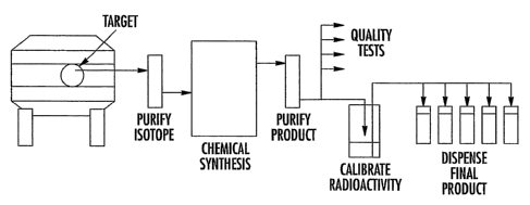
radioisotope-labeled PET molecular imaging probe production process is shown
in
Fig. 1. As shown therein, PET radiotracers are produced using automated or
manual chemistry synthesis techniques to convert raw isotope generated in a
cyclotron to a useable, injectab~e compound. Cyclotrons accelerate ionized
particles and bombard target material, such as enriched [180] water, to
produce the
raw isotope. This target material is removed, once activated, and purified
before
introduction to the synthesis process. Chemical synthesis converts the raw
isotope
into the desired compound and is typically followed by purification of the
product.
Chemical products are accurately calibrated for radioactivity and are
subjected to a
battery of quality control tests. Product batches are then dispensed into
smaller
batches or doses either manually or with automated equipment and shipped to
the
customer. In the process of the present invention, some or all of the above
process
steps are performed within a microfluidic environment.
For example, for a process utilizing fluorine-18 fluoride ion, one or more of
the following steps can be performed in a microfluidic device according to the
present invention:
~ Receive aqueous [18F] fluoride ion from the cyclotron target
~ Separate the [18F] fluoride ion from the water and collect the water
~ Generate a solution of reactive [18F] fluoride ion in an organic or other
polar
aprotic solvent (acetonitrile, DMF, DMSO, etc.)
~ Provide a solution of a reactive precursor in an organic or other polar
aprotic
solvent (acetonitrile, DMF, DMSO, etc.)
-15-
CA 02523189 2005-10-21
WO 2004/093652 PCT/US2004/012189
~ React the [18F] fluoride ion with the precursor using a SN2 nucleophilic
substitution reaction to create a new carbon-fluorine bond, using heat if
necessary
~ Purify the initial [18F] fluorinated product by solid phase extraction or
chromatography
~ React the purified initial [18F] fluorinated product with a second reagent
to
generate the final [18F] fluorinated product (e.g., hydrolysis of protecting
group(s), if necessary)
~ Purify the final (18F] fluorinated product by, for example, solid phase
extraction
or chromatography
~ Desolvate the [18F] fluorinated product
~ Assay the purified final [1$F] fluorinated product for radioactivity, UV
absorbance, and conductivity/pH
~ Deliver the purified final [1$F] fluorinated product
~ Dispense the purified final [18F] fluorinated product
For a process utilizing a carbon-11-labeling agent (e.g., methyl iodide,
methyl triflate, carbon monoxide, hydrogen cyanide), any of the following
steps
can be performed within a microfluidic device according to the present
invention:
Receive [irC]-labeling agent from the cyclotron target or post-irradiation
processor
~ Generate a solution of reactive [11C]-labeling agent in an organic and/or
polar
aprotic solvent (acetonitrile, DMF, DMSO, etc.)
~ Provide a solution of a reactive precursor in an organic and/or polar
aprotic
solvent (acetonitrile, DMF, DMSO, etc.)
~ React the [11C]-labeling agent with the precursor using a SN2 nucleophilic
substitution reaction or other suitable reaction to create a new carbon-
nitrogen,
carbon-oxygen, carbon-sulfur or carbon-carbon bond, using heat or microwave
energy if necessary
~ Purify the initial [11C]-labeled product by, for example, solid phase
extraction
or chromatography
~ React the purified initial [11C]-labeled product with a second reagent to
generate the final [11C]-labeled product (e.g., hydrolysis of protecting
group(s),
if necessary)
-16-
CA 02523189 2005-10-21
WO 2004/093652 PCT/US2004/012189
~ Purify the final [11C]-labeled product by solid phase extraction or
chromatography
~ Assay the purified final [11C]-labeled product for radioactivity, UV
absorbance,
and conductivity/pH
~ Desolvate the [11C]-labeled product
~ Deliver the purified final [11C]-labeled product
~ Dispense the purified final [liC]-labeled product
The microfluidic devices of the present invention can be manufactured using
commercially available equipment from a number of suppliers, such as Caliper
Technologies, Inc., MCS, Fluidigm, Nanostream, and CPC-Systems.
A micro reactor-based radiochemical synthesis system typically comprises a
micro reactor and the associated processing and control equipment required for
performing the synthesis and delivering the product. In one embodiment, the
radiochemistry micro reactor comprises a series or network of interconnecting
microchannels that can be either cut or etched into a solid substrate (i.e., a
microchip) or can comprise an assembly of glass, metal, or polymeric capillary
tubing and fittings.
If a solid substrate is used, the micro reactor may comprise a microchannel
network in a single layer or multiple layers of microchannels in a single chip
with
interconnects, if desired, connecting one layer to another. The wetted
surfaces of
the solid substrate and/or capillary tubing and fittings should be constructed
of a
material that is inert and compatible with the organic solvents and reagents
used,
such as glass, quartz, metal, or appropriate polymeric material (e.g., PEEK,
PTFE,
polystyrene, polypropylene, or acrylic polymers). The solid substrate micro
reactor may be fabricated using commercially known fabrication techniques,
including but not limited to standard photolithographic procedures and wet
chemical etching, with the substrate and cover plate joined using direct
bonding in
glass substrates and embossing in polymeric substrates.
The microchannels are in fluid communication with reservoirs for the
various reagents, precursors and solvents that may be housed within the micro
reactor or located remote from the micro reactor. The microchannels are also
in
fluid communication with reservoirs for the products) and for waste materials.
Using the microchannels, the reagents and solvents can be brought together in
a
-17-
CA 02523189 2005-10-21
WO 2004/093652 PCT/US2004/012189
specific way and allowed to react in a controlled region of the microchannel
network. Multiple ports and reservoirs may be employed as required to allow
mufti-step radiochemical synthesis sequences, where for example the precursor
is
reacted with the radioactive isotope, and then in a subsequent step (after
purification if necessary), protecting groups are removed to yield the desired
product.
The reagents and solvents can be moved through the microchannel network
using any fluid propulsion method known in the art of microfluidics, such as
electrokinetic methods (electroosmotic and electrophoretic) and/or
hydrodynamic
pumping. For electrokinetic pumped systems, electrodes are placed in
appropriate
positions such that specific voltages are delivered under microprocessor
control.
These voltages cause the reactants and products to move and be separated in
the
channels. Hydrodynamic pumping uses appropriate external and/or internal
pumps, tubing, fittings and valves to move the reactants and products through
the
channels by applying a positive pressure to one or more of the inlet ports of
the
micro reactor. Valves of any type known in the art of microfluidics, such as
rotary
switching valves, etched cantilever beams, bubble actuated, and inertial
valves, can
be placed at the miGrochannel junctions to direct flow. Laminar flow with a
planar
velocity profile characterizes the principles of operation inside the
microchannels
and can be utilized to control diffusion and reaction properties.
Monitoring of the reactants and products may be accomplished using
various sensors and detectors that can be integrated into the micro reactor.
For
example, pH sensors, conductivity sensors, radiation sensors, and liquid and
gas
chromatography devices can be integrated into the microfluidic apparatus.
Alternatively, the sensors and detectors can be used remotely from the micro
reactor for analysis and testing.
A number of exemplary embodiments are described below. These
embodiments are provided for illustrative purposes only and should not be
construed as limiting the invention. For example, it would be understood that
microchips comprising additional ports, reservoirs or microchannels not shown
in
the exemplary structures described below could be readily utilized in the
present
invention.
-18-
CA 02523189 2005-10-21
WO 2004/093652 PCT/US2004/012189
In a version of a micro reactor 10 of the invention shown in Fig. 2, the
microchannels, 12a, 12b, and 12c, are formed by connecting three lengths of
capillary tubing to a T-shaped member 16. The reactants are introduced through
parts or reservoirs at each end of the channels, 12a and 12b, forming the
cross of
the "T" and are brought together through the "T junction" to react in the
third
channel 12c. The product is delivered to a reservoir 18 at the end of the
reaction
channel 12c. A portion 14 of the reaction channel 12c can be heated by a
heating
source 22 to promote the desired reaction. Pumps, such as syringe pumps, 20a
and
20b, are used to propel the reagents through the micro reactor 10. Any heating
unit
can be used as heating source 22, including but not limited to resistive
heating,
localized and non-localized microwave heating and Peltier devices. Exemplary
pumps for use in the invention include but are not limited to a Harvard PHD
2000
syringe pumps. An embodiment of the device shown in Fig. 2 was used in
Examples 1 and 2.
Fig. 3 illustrates a further embodiment of a micro reactor 10 comprising a
first microchip 24 and a second microchip 26. The first microchip 24 is
designed
to react a radioactive isotope with a reactive precursor and the second
microchip 26
is designed to deprotect the radiochemical product of the first microchip. The
first
microchip 24 comprises an interconnecting microchannel network comprising a
first microchannel segment 28a in fluid communication with a first inlet 30 of
the ,
microchip, a second microchannel segment 28b in fluid communication with a
second inlet 34 of the microchip, and a third microchannel segment 28c in
fluid
communication with the outlet 36 of the microchip. As shown, all three
microchannel segments intersect within the microchip 24. The first inlet 30 of
the
first microchip 24 is in fluid communication with a supply 40 of a radioactive
isotope, such as a solution of 1$F fluoride. As noted above, the supply 40 of
radioactive isotope is preferably a solution of radioactive isotope dissolved
in a
polar aprotic solvent. The second inlet 34 of the first microchip 24 is in
fluid
communication with a supply 44 of a reactive precursor, such as a supply of a
liquid organic precursor dissolved in a polar aprotic solvent as described
above.
The outlet 36 of the first microchip 24 is in fluid communication with a
first inlet 46 of the second microchip 26. Preferably, capillary tubing having
an
inner diameter of no more than lmm is used to connect the two microchips. As
-19-
CA 02523189 2005-10-21
WO 2004/093652 PCT/US2004/012189
shown, it is preferred for the efrluent from the first microchip 24 to pass
through a
heat exchanger 56 to reduce the temperature of the effluent prior to
introducing the
effluent into the second microchip 26. The heat exchanger can be any known
type
of heat exchanger, such as a water bath or other liquid maintained at a known
temperature. The second inlet 50 of the second microchip 26 is in fluid
communication with a supply 52 of an aqueous base solution. The microchannel
network of the second microchip 26 includes a first microchannel segment 54a
in
fluid communication with a first inlet 46 of the microchip, a second
microchannel
segment 54b in fluid communication with a second inlet 50 of the microchip,
and a
third microchannel segment 54c in fluid communication with the outlet 58 of
the
microchip. As shown, all three microchannel segments intersect within the
microchip 26.
Both microchips are in contact with a heat source, 60a and 60b, capable of
heating each microchip independently. Suitable heat source include but are not
limited to resistive heating, localized and non-localized microwave heating
and
Pettier devices. As would be understood, various sensors (e.g., flow sensors,
radioactivity sensors, pressure sensors, temperature sensors, and the like)
and other
apparatus components (e.g., valves, switches, etc.) (not shown) can be
integrated
into the micro reactor 10 and connected to a computer 64 for process control
and
monitoring purposes. Syringe pumping systems or other pumping devices (not
shown), such as the syringe pumping system described below in connection with
Fig. 4, can be incorporated into the micro reactor 10 in order to propel the
reagents
through the microchannels. Preferably, the reagents flow through each
microchip
in laminar flow and at a flow rate of about 1 to about 120 p.L,/min.
In operation, radioactive isotope will flow into the first microchip 24 from
the isotope supply 40 and reactive precursor will flow into the first
microchip from
precursor supply 44. The two reactants will contact each other and react in a
microchannel 28c of the microchip 24. The heat source 60a maintains the
microchannel network at the desired reaction temperature, which is preferably
at
least about 85°C, more preferably at least about 95°C. In one
embodiment, the
temperature of the microchannel network of the first microchip 24 is
maintained at
a temperature of about 60 to about 100°C, preferably 85 to
100°C. The preferred
reaction temperature for optimal yield is above the boiling point (at 1 atm)
of
-20-
CA 02523189 2005-10-21
WO 2004/093652 PCT/US2004/012189
certain preferred polar aprotic solvents, such as acetonitrile. As a result,
it is
preferred to maintain the pressure within the microchannel network of the
first
microchip 24 at a level sufficient to maintain the solvent in liquid form at
the
desired reaction temperature. In one embodiment, the pressure in the first
microchip 24 is at least about 2 bar, more preferably at least about 4 bar.
Preferably, the pressure in the first microchip 24 is between about 2 and
about 400
bar. The pressure in the first microchip 24 can be elevated to the desired
level by,
for example, connecting capillary tubing having a smaller inner diameter than
the
microchannel network of the first microchip to the outlet 36 of the first
microchip.
The effluent from the fist microchip 24 passes through a heat exchanger 56
that reduces the temperature of the effluent, preferably to a temperature of
about 0
to about 30°C. In one embodiment, the heat exchanger is a water bath
having a
temperature of about 0 to about 30°C, the capillary tubing carrying the
effluent
from microchip 24 being immersed in the water bath. Thereafter, the cooled
effluent from the first microchip 24 in introduced into the second microchip
26
along with base from base supply 52. The second microchip 26 is maintained at
a
desired temperature using the associated heat source 60b. Preferably, the
microchannel network of the second microchip 26 is maintained at a temperature
of about 0 to about 35°C, more preferably about 20 to about
35°C. The
radiochemical in the effluent stream from the first microchip 24 contacts the
base
and reacts with the base to remove protecting groups from the radiochemical by
hydrolysis. For example, in the synthesis of [i8F]FDG, the effluent stream
from
the first microchip 24 may contain 2-deoxy-2-[1gF] fluoro-1,3,4,6-tetra-O-
acetyl-(3-
D-glucose, wherein the acetyl protecting groups are removed by reaction with
the
aqueous base solution (i.e., by hydrolysis) to form the final desired product.
The
product stream is then collected from outlet 58 of the second microchip 26.
Fig. 4 illustrates an embodiment of one preferred syringe pumping system
68 that can be used with the present invention. As noted above, a syringe or
other
suitable pumping system or other pumping apparatus can be utilized to propel
each reagent through the microchannels of the micro reactor 10. In one
embodiment, a syringe pumping device is used to pump each reagent through the
micro reactor 10, meaning a syringe pumping system is provided for the
reactive
precursor, the isotope-containing solution, the base solution, and any other
-21-
CA 02523189 2005-10-21
WO 2004/093652 PCT/US2004/012189
solutions adapted for pumping through the micro reactor, such as wash solvents
and the like. Preferably, each of the reagents (e.g., isotope, reactive
precursor, and
base solution) are pumped through the micro reactor 10 using a separate
syringe
pumping apparatus. As shown in Fig. 4, a preferred syringe pumping system 68
comprises a first syringe 70 and a second syringe 72, wherein the second
syringe is
of sufficient size to aspirate a volume twice the volume of the first syringe.
The
two syringes, 70 and 72, are in fluid communication with each other such that
the
two syringes are capable of providing continuous flow by sequentially
aspirating
and dispensing.
As shown, a fast valve 76 is in fluid communication with the second larger
syringe 72 so that the source from which the second syringe aspirates can be
switched as desired. A second valve 78 is operatively positioned doumstream
from
the first valve 76 so as to control the destination of the material being
pumped. In
this manner, the second valve 78 is used to direct the material being pumped
to, for
example, the micro reactor or a waste port. A pressure sensor 80 is preferably
placed in fluid communication with the two syringes, 70 and 72. As shown, the
pressure sensor can be placed in a line leading to a waste port 82.
In operation, as the second larger syringe 72' dispenses, the first syringe 70
aspirates half of the volume dispensed by the second syringe. Once the second
syringe 72 has completed dispensing, the first syringe 70 begins dispensing
and the
second syringe begins to aspirate from the desired source, which can be
controlled
by manipulating the first valve 76. This cycle continues to achieve continuous
flow through the microfluidic environment.
Fig. 5 illustrates a micro reactor 10 embodiment wherein the reservoirs,
86a, 86b, and 86c, of the reagents used in the radiochemical synthesis process
are
located in the microfluidic environment (i.e., on the microchip), thereby
further
exploiting the advantages of manipulating fluids at the micro scale. The
integration of reagent reservoirs on the microchip will greatly reduce the
volume of
reagents. consumed due to less dead volume, simplify design, and increase
reliability of the system. A single chip could be a self contained disposable
or
reusable device that has everything required for synthesis of a compound and
thus
replacing the much larger and more complex synthesis instruments that are
current
state of the art.
-22-
CA 02523189 2005-10-21
WO 2004/093652 PCT/US2004/012189
Fig. 6 illustrates a micro reactor 10 embodiment integrated with the target
body assembly 90 where the radioisotope is collected. Current state of the art
PET
radiochemical synthesis requires bombardment of target material in a
cyclotron,
then unloading the target to automated or manual chemistry synthesis
instruments.
Volumes are typically 1 to 5 ml and transport distances can be up to 100 feet.
By
integrating microfluidic channels, reservoirs, devices, arid reactors, many
chemical
processes can be performed local to the target. Figure 6 illustrates an
embodiment
where reagents are stored in reservoirs, 86a, 86b, ~,nd 86c, on the same
microfluidic chip that is integrated with the target assembly 90 and proximal
to the
metal target 92 loaded with target material. This allows immediate local
synthesis,
reducing time, risk of contamination, radiation exposure, and considerably
reduces
cost. Further integration is shown in Figure 7, which illustrates a micro
reactor 10
wherein a target chamber 94 and a plurality of reagent chambers, 86a, 86b, and
86c, are etched into a single microfluidic chip along with the interconnecting
microchann~l network 96. This embodiment of the micro reactor 10 should be
constructed of a thermally conductive, chemically resistant material.
Fig. 8 is a further micro reactor 10 embodiment that integrates the metal
cyclotron target 90 with the microfluidic device in a bonded or coupled
assembly.
In this embodiment, the target material is passed from the metal target 92 to
the
adjoining microfluidic chip and processed in a recirculating continuous flow
pattern proximal to the micro-reactor where the activated isotope is removed
and
the unactivated target material returns to the target for irradiation. The
activated
isotope is further processed inside the microfluidic chip to produce the
positran-
emitting molecular imaging probe. In this manner, the target material is
continuously bombarded in a cyclotron while being circulated out of the beam
strike area to allow the activated isotope to be trapped, then recirculated
back into
the beam strike area. Thus, radioisotopes can be continuously processed in
real-
time as needed.
Fig. 9 illustrates a micro reactor 10 embodiment including sensors, 100x,
100b, and 100c, integrated into the microfluidic structure. The use of
integrated
microfluidic sensors/detectors, such as pH sensors, conductivity sensors,
radiation
sensors, liquid and gas chromatography devices, and mass spectroscopy devices,
will allow in-process measurements of starting materials, intermediate
materials,
-23-
CA 02523189 2005-10-21
WO 2004/093652 PCT/US2004/012189
and final products generated in the microfluidic circuit. A computer 64
comprising
control software can utilize these in-process measurements to adjust flow or
reaction parameters and test for clogs, leaks, or reaction failures in real-
time and
then make decisions on how to correct any deviations in the continuous flow
process of the microfluidic circuit. Current technology operating at the
macroscale
utilizes in-process sensing of radiation, temperature, and pressure, but has
no
automated capability to correct the batch mode processes.
Current state of the art production techniques require PET radiolabeled
products to be purified following synthesis to be useful injectable compounds.
Current purification techniques include HPLC separation and or solid phase
extraction to remove unwanted elements and to purify the final product. In one
embodiment of the present invention shown in Fig. 10, such purification
processes
are also integrated into the micro reactor 10 device. Tncorporation of both
solid
phase resins and in-line HPLC column 102 onto the microfluidic chip will allow
continuous flow product purification in a much smaller volume with greatly
improved reliability. In addition to these techniques, Fig. 11 illustrates the
use of
electrokinetic flow as an additional means to separate constituents and to
extract
the purified final product. In this embodiment, electric fields are applied to
separate constituents by capillary electrophoresis and electrochromatography
using
an electrokinetic separation device 106. Further, by utilizing the electric
potential
and viscous drag differences of unlike molecules, constituents can be
separated and
concentrated in a microfluidic channel by driving electrokinetically in one
direction, and hydraulically in the opposite direction. Once separated and
concentrated, the constituents can be directed into channels for dispensing or
further separation.
One of the key strengths in microfluidic design is the ability to parallel
process solutions with high accuracy and minimal loss. To leverage this
capability, one embodiment of the present invention,-shown in Fig. 12, the
microfluidic device 10 is configured to produce multiple PET radiotracers or
multiple paths of the same tracer in parallel. The radioactive isotope would
be
transferred from the cyclotron to the microfluidic chip, then separated and
processed in parallel as needed. Redundancy gives the system improved
reliability
and capability to automatically correct problems detected during synthesis.
Fig. 12
-24-
CA 02523189 2005-10-21
WO 2004/093652 PCT/US2004/012189
illustrates five parallel circuits for five different nucleophilic processes.
This
concept can be applied to electrophilic and gas processing as well as multiple
channels of the same process.
The micro reactor 10 embodiment of Fig. 13 includes integration of
radiation measurement and accurate volume control, which allows on-chip
quantification of activity per unit volume and the automatic dispensing of
calibrated dose volumes. An inline sensor 108 measures radioactivity as the
liquid
moves through the chip or is accumulated in an on-chip chamber. For instance,
beta radiation can be measured by integrating a semiconductor layer with
etched
photo diodes in the microfluidic chip that is in close proximity to the
microchannel. Gamma radiation can be measured using scintillating detectors in
single photon and coincidence photon collection configurations. Computer
control
dispenses the desired amount of activity into product containers 110 and also
adds
saline to deliver the desired volume.
In yet another embodiment of the present invention, the radioactive isotope
is separated from the target liquid via a separation device integrated into
the
microfluidic device, as shown in Figs. 14 and 15. An exemplary device
including
an ion exchange resin as the radioisotope separation device is shown in Fig.
14. As
shown, micro reactor 10 comprises a port 112 wherein the radioactive isotope
in
the target liquid is introduced into the device and allowed to flow across ion
exchange resin 114 and into microchannel 116. The radioactive isotope remains
ionically bound to resin 114 while the liquid flows through microchannels 116
and
118 to waste target liquid port 120. A polar aprotic solvent is introduced
into the
microchip 10 through a port 122. The polar aprotic solvent flows through
microchannels 116 and 118 to collection port 124. This step is essential as it
serves to clean the microchannels of microchip 10 before the organic precursor
and
the radioactive isotope are allowed to come in contact. An eluent dissolved in
a
polar aprotic solvent is introduced into the microchip 10 through port 126 and
the
radioactive isotope is ionically exchanged for the counter ion in the eluent
as it
passes through resin 114, thus releasing the isotope into the polar aprotic
solvent.
The organic or inorganic precursor is then introduced to the microchip 10
through
port 128. The polar aprotic solvent containing the isotope and the precursor
meet
at the junction of microchannels 116 and 118. The two reactants react to form
the
-25-
CA 02523189 2005-10-21
WO 2004/093652 PCT/US2004/012189
positron-emitting molecular imaging probe in microchannel 118 and the product
is
collected in product port 130.
Fig. 15 illustrates an embodiment of microchip 10 wherein the isotope
separation device is an electrolytic cell. As shown, microchip 10 comprises a
port
112 wherein the radioactive isotope in the target liquid is introduced into
the
device and allowed to flow across electrolytic cell 132, which comprises an
anode
134 and a cathode 136, and into microchannel 116 while a voltage is applied to
the
electrolytic cell by a DC power supply 138. The radioactive isotope remains on
the anode 134 of the electrolytic cell 132 while the target liquid flows
through
microchannels 116 and 118 to target liquid port 120. The voltage across the
electrolytic cell 132 is maintained while a polar aprotic solvent flows from
port
122 through microchannels 116 and 118 to collection port 124. Polar aprotic
solvent is again introduced through port 122 and the voltage from power supply
138 is reversed, thereby releasing the isotope into the polar aprotic solvent.
The
organic precursor is then introduced to the microchip 10 through port 128. The
polar aprotic solvent containing the isotope and the precursor meet at the
junction
of microchannels 116 and 118. The two reactants react to form the positron-
emitting molecular imaging probe in microchannel 118 and the product is
collected
in product port 130.
The anion exchange resin or electrochemical cell shown in Figs. 14 and 15
could be integrated on the microchip or could be a separate unit that
interfaces with
the microchip. Multiple anion exchange resin modules or multiple
electrochemical
cells could be present on a single chip allowing multiple syntheses to take
place on
the same chip unit.
The following examples are given to illustrate the invention, but should not
be considered in limitation of the invention. Unless otherwise indicated, all
conversion data was obtained by collecting a sample and spotting 1-2~,L of the
sample onto a Whatman aluminum backed SIL G TLC plate. The plate was then
developed in a TLC chamber using a 95%/5% acetonitrile/water (v/v) mixture as
the mobile phase. After development, the plate was scanned wing a Bioscan AR
2000 radio-TLC scanner. Unless otherwise noted, each 1$F solution used in the
experiments comprises Kryptofix 2.2.2/K2C03/18F- dissolved in acetonitrile.
Mannose triflate referred to in the examples is also known as 1,3,4,6-tetra-O-
-26-
CA 02523189 2005-10-21
WO 2004/093652 PCT/US2004/012189
acetyl-2-O-trifluoromethanesulfonyl-j3-D-mannopyranose. Measurements of pH
were made using Universal Indicator solution.
Example 1
Radiochemical Synthesis of [18F] fluoroethyl tos,
An embodiment of the micro reactor of the invention, which is shown in
Figure 2, was constructed using fused silica capillary tubing (360 N,m OD x
100
p,m ID) and Microtight~ fittings (ITpchurch Scientific). Twa pieces of
capillary
tubing exactly 25 cm long were attached to the opposite sides of a MicroTee
(Part
No. P-775, Upchurch Scientific, 150 pm thru-holes, 29 nL swept volume) and a
third piece of capillary tubing 2 m long was attached to the remaining
orthogonal
position on the MicroTee. The chemical and radiochemical reagents were
introduced into and moved through the reactor using a syringe pump (Harvard
PHD 2000) and two 1 mL polypropylene syringes. A central 125 cm portion of the
2 m reaction channel was formed into faur 10 cm diameter loops that were
secured
together. This section of four loops was placed in a water bath that was
heated to
65-70°C. The output end of the reaction channel was placed into a small
test tube
that contained 700 p.I, of acetonitrile.
Ethylene glycol di-tosylate (8.4 mg, 22.7 E~,mol) was dissolved in 200 ~.L,
acetonitrile, and about 140 p.I, of this solution (containing 15.9 E.irnol)
was loaded
into one of the 1 mL syringes. Dry [18F] fluoride ion in acetonitrile was
prepared
by the standard method: [180] water was irradiated with 11 MeV protons. At the
end of bombardment the [180] water was transferred through a small anion
exchange resin (M1-1) column to trap the [18F] fluoride ion. The [18F]
fluoride ion
was then released from the resin column using 0.6 mL of potassium carbonate
(2.8
mg) in water, and delivered into a vessel containing a solution of I~ryptofix
222
(1.0 g) in acetonitrile (1 mL).
The acetonitrile was evaporated and three additional portions of acetonitrile
(0.6 mL) were added and evaporated. After cooling, acetonitrile (250 p.I,) was
added to the dry [18F] fluoride ion residue, mixed by bubbling with argon, and
140
~.I, of this solution was transferred to the other 1 mL syringe. This solution
contained about 260 mCi of [18F] fluoride ion. Once the two syringes were
loaded
with edual volumes of reagent solution, the syringe pump was started at a flow
rate
-27-
CA 02523189 2005-10-21
WO 2004/093652 PCT/US2004/012189
of 4 p,L,/min. After 1 minute the flow rate was changed to 1.0 p,I,lmin. The
two
solutions were pumped through the 2 m reaction channel that included the 125
cm
portion heated to 65-70°C. At 1 p.L,/min, the reagents had a residence
time of 5
minutes in the heated reaction zone. After about 100 minutes, the collected
product
solution was diluted with acetonitrile to make the total volume equal to 1 mL.
The
product reaction mixture was injected onto a semi-prep HI'LC column
(Phenomenex Luna, Sp, C18, 250 x 10 mm, mobile phase acetonitrilelwater,
50:50,
4 mL/min), and the eluent monitored using UV at 254 nm and a flow-through
radioactivity detector. The unreacted [18F] fluoride ion eluted at about 3
minutes,
and the desired [18F] fluoroethyl tosylate eluted at 1~-15 minutes.
Example 2
Radiochemical synthesis of 2-deox~[1$F] fluoro-1 3,4 6 tetra O acetyl ~3 D
lucose
Using the same micro reactor apparatus described in Example 1 above, a
solution of mannose triflate (4.4 mg, 9.2 p,rnol)) in acetonitrile (140 p.I,)
was
loaded into a 1 p.L, syringe. An anhydrous solution of [18F] fluoride ion (210
mCi)
in 140 p,I, of acetonitrile (prepared as described in Example 1 above) was
transferred to a second 1 p.L syringe. Once the two syringes were loaded with
equal
volumes of reagent solution, the syringe pump was started at a flow rate of 4
p.I,lmin. After 1 minute the flow rate was changed to 1.0 p.L,/min. The two
solutions were pumped through the 2 m reaction channel that included the 125
cm
portion heated to 65-70°C over a period of 100 minutes. After about 100
minutes,
the collected product solution was analyzed by radioTLC (silica gel, ether).
In
addition to unreacted [18F] fluoride ion at Rf= 0.0, the desired
radiofluorinated
product was detected at Rf= 0.65.
Example 3'
Radiochemical synthesis of 2-deoxy-2-[i8F] fluoro-1 3,4 6 tetra O acetyl ~3 D
lucose
[18F] fluoride ion in acetonitrile was prepared by the following method:
[180] water was irradiated with 11 MeV protons. At the end of bombardment the
[180] water was transferred through a Waters QMA Light anion exchange
cartridge
to trap the [18F] fluoride ion. The [18F] fluoride ion was then released from
the
-28-
CA 02523189 2005-10-21
WO 2004/093652 PCT/US2004/012189
resin column using 1.0 mL of potassium carbonate {5.5 mg) in a solution of
97.5%
acetonitrile/2.5% water by weight. This mixture was delivered in to a 20mL
glass
vial where an additional 9mL of dry acetonitrile was added. This resulted in a
[l8F] fluoride solution containing 0.25% water in acetonitrile by weight.
A micro reactor system was constructed using a microchip having a T-
shaped microchannel with two inlet ports and an outlet port. Using a Hamilton
Company, having an address of 4970 Energy Way, Reno, NV 89502, syringe
system comprising SGE gas tight syringe needles, a solution of mannose
triflate
and a [18F] fluoride solution, prepared as described above in this example,
were
pumped separately into an inlet of the microchip. The outlet was connected to
a
2m length of fused silica capillary, 100pm x 360p,m, of which 1.4m was placed
into an oil bath allowing heating of the reaction zone. The system was allowed
to
equilibrate for 15 minutes at a flow rate of 5 ~.L,/min and the product was
collected
for a period of 3 minutes into a HPLC vial for analysis by TLC. Highest yield
observed: 63%.
Example 4
Radiochemical synthesis of 2-deoxy-2-[18F]' fluoro-1,3 4,6-tetra-O-acetyl-~3-D-
lug rose
The micro reactor system of Example 3 was used, except the oil bath was
placed in a water bath'to improve temperature control and stability and held
at a
temperature of 95°C. The [18F] fluoride solution was prepared in the
same manner
as in Example 3. A solution of mannose triflate and an isotope containing
solution
consisting of fluorine-18 fluoride containing 0.25% water by volume were
pumped separately into an inlet of the microchip. The system was allowed to
equilibrate for 5 minutes at a flow rate of 5 pL !min and the product was
sampled
straight from the capillary onto the TLC plate. Highest yield observed: 91%.
Example 5
Radiochemical synthesis of 2-deoxy-2-[18F] fluoro-1 3 4,6-tetra-O-acetyl-1-J3-
D-
lug core
The micro reactor system of Example 4 was used, except a second fused
silica capillary section was connected to the outlet, the second capillary
section
-29-
CA 02523189 2005-10-21
WO 2004/093652 PCT/US2004/012189
being 2m in length, 75~.m x 360 ~,m, which increased the back pressure by 2.6
Bar.
The second outlet capillary section was placed in a cooled water/ice bath. The
[1sF] fluoride solution wvas prepared in the same manner as in Example 3. The
syringes were set at 10 ~,I,lmin and the product was collected for 3 minutes
into a
HPLC vial for analysis by TLC. Average yield: 91.0%.
Example 6
Radiochemical synthesis of 2-deox~[rgF] fluoro-1,3,4,6-tetra-O-acet~(3-D-
lucose
The micro reactor system of Example 5 was used to determine erect of
temperature and flow rate on yield. The [18F] fluoride solution was prepared
in the
same manner as in Example 3. Multiple experimental runs were conducted at
varying flow rates while holding the reaction temperature constant and at
varying
temperature while holding the flow rate constant. Increasing yield was
observed as
temperature increased. Decreasing yield was observed with increasing flow
rate. A
constant flow rate of 20 ~,1/min at a reaction temperature of 98°C
resulted in an
average yield of 97.7%.
Example 7
Radiochemical synthesis of 2-deo~r-2-f i8F) fluoro-1 3,4,6-tetra-O-acetyl-[3-D-
lucose
A micro reactor system was constructed using a two channel Syrris Ltd.,
having an address of 27 Jarman Way, Royston, Herts, SG8 SHW, United Kingdom
pump module attached to a microchip manufactured by Microch~mical Systems
Ltd., having an address of The Deep Business Center, Hull, HU1 4BG, United
Kingdom, having two inlets and an outlet. The [1$F] fluoride solution was
prepared in the same manner as in Example 3. One channel of the pump was used
to deliver mannose triflate to the first inlet of the microchip and the other
channel
was used to deliver the 18F solution. The microchip was loaded into a PEEK
carrier and placed in a Peltier heating unit manufactured by Syrris Ltd. with
the
base of the microchip in contact with the heating unit. The system was plumbed
using PTFE capillary tubing (1/16" and 1/32" o.d.) and connected to the
microchip
using Upchurch Nanoport fittings.
-30-
CA 02523189 2005-10-21
WO 2004/093652 PCT/US2004/012189
Mannose triflate and the 18F solution were driven from their respective
channels of the pump module into the two inlet ports of the microchip. The
Peltier
heater was used to heat the microchannel of the microchip to a temperature of
100°C. The temperature of the microchip was measured by placing
temperature
sensors (e.g., a thermocouple) adjacent to the top and bottom surfaces of the
microchip. The actual temperature in the microchannel can be interpolated
using
this temperature data. To the outlet of the microchip was connected PTFE
tubing
terminating with a PEEK needle. Output from the needle was collected into a
vial
charged with 10,1 of water to quench the reaction.
At a flow rate of 20 ~,I,/min and a reaction temperature of 100°C,
an
average yield (i.e., percent conversion of mannose triflate to [i8F] FTAG
(tetra-
acetyl glucose)) was 99.47%, meaning the conversion was essentially
quantitative.
Example 8
Radiochemical synthesis of 2-deox~~ 2-[1gF] fluoro-D-glucose ([lgFaFDGI
To the micro reactor system of Example 7, a second microchip was added
such that the system embodied the general configuration shown in Fig. 3. The
[i8F]
fluoride solution was prepared in the same manner as in Example 3. The second
microchip was also heated using the Peltier heating unit and the output from
the
first microchip was directed through 200 mm of PTFE capillary tubing (220 ~,m
i.d., 1/32" o.d.) to an inlet of the second microchip. A second Syrris pump
module
was used to deliver 1N aqueous sodium hydroxide to the second inlet of the
second
microchip. The microchannel of the second microchip was maintained at a
temperature of 30°C and monitored using top and bottom temperature
sensors as
with the first microchip. The output of the second microchip was connected to
the
PEEK needle assembly described in Example 7 and the product was collected in a
vial containing 300 ~,I, of water and 80 p.L, of EtOH. Operating at a flow
rate of 20
p,L/min, the effluent was collected for one minute and then the pH of the
contents
of the vial was brought to around neutral by dropwise addition of O.SN aqueous
hydrochloric acid. Average yield was 89.00%. The lower yield as compared to
Example 7 suggests that some decomposition of FTAG or FDG occurs under these
conditions.
-31-
CA 02523189 2005-10-21
WO 2004/093652 PCT/US2004/012189
Many modifications and other embodiments of the invention will come to
mind to one skilled in the art to which this invention pertains having the
benefit of
the teachings presented in the foregoing description. Therefore, it is to be
understood that the invention is not to be limited to the specific embodiments
disclosed and that modifications and other embodiments are intended to be
included within the scope of the appended claims. Although specific terms are
employed herein, they are used in a generic and descriptive sense only and not
for
purposes of limitation.
-32-