Language selection

Search

Patent 2523192 Summary

Third-party information liability

Some of the information on this Web page has been provided by external sources. The Government of Canada is not responsible for the accuracy, reliability or currency of the information supplied by external sources. Users wishing to rely upon this information should consult directly with the source of the information. Content provided by external sources is not subject to official languages, privacy and accessibility requirements.

Claims and Abstract availability

Any discrepancies in the text and image of the Claims and Abstract are due to differing posting times. Text of the Claims and Abstract are posted:

  • At the time the application is open to public inspection;
  • At the time of issue of the patent (grant).
(12) Patent: (11) CA 2523192
(54) English Title: TURBINE SHROUD SEGMENT SEAL
(54) French Title: JOINT D'ETANCHEITE DE NAGEOIRE PERIPHERIQUE DE TURBINE
Status: Granted
Bibliographic Data
(51) International Patent Classification (IPC):
  • F01D 11/10 (2006.01)
  • F01D 11/12 (2006.01)
(72) Inventors :
  • SYNNOTT, REMY (Canada)
  • BLAIS, DANY (Canada)
(73) Owners :
  • PRATT & WHITNEY CANADA CORP. (Canada)
(71) Applicants :
  • PRATT & WHITNEY CANADA CORP. (Canada)
(74) Agent: NORTON ROSE FULBRIGHT CANADA LLP/S.E.N.C.R.L., S.R.L.
(74) Associate agent:
(45) Issued: 2012-07-10
(22) Filed Date: 2005-10-12
(41) Open to Public Inspection: 2006-04-15
Examination requested: 2008-06-25
Availability of licence: N/A
(25) Language of filing: English

Patent Cooperation Treaty (PCT): No

(30) Application Priority Data:
Application No. Country/Territory Date
10/965,234 United States of America 2004-10-15

Abstracts

English Abstract

A ring seal for sealing an annular gap defined between opposed surfaces of concentric inner and outer annular engine parts in a gas turbine engine. The ring seal being wholly disposed within the annular gap and having a wave pattern with alternating peaks. The ring seal radially inwardly loads the inner engine part and provides a fluid seal between the inner and outer engine parts.


French Abstract

Une bague d'étanchéité pour sceller un écart annulaire défini entre des surfaces opposées de pièces de moteur annulaires extérieures et intérieures concentriques de moteur de turbine à gaz. La bague d'étanchéité étant entièrement disposée dans l'écart annulaire et étant dotée d'une formation ondulée avec des pics en alternance. La bague d'étanchéité charge vers l'intérieur de manière radiale la pièce de moteur interne et fournit un joint d'étanchéité fluidique entre les pièces de moteur intérieures et extérieures.

Claims

Note: Claims are shown in the official language in which they were submitted.


CLAIMS:
1. A ring seal for sealing an annular gap defined between opposed surfaces of
concentric inner and outer annular engine parts in a gas turbine engine, said
opposed surfaces being radially spaced apart by a first distance, said ring
seal
being wholly disposed within said annular gap and having a wave pattern
with at least two alternating peaks defining an uncompressed radial height
therebetween greater than said first distance, said ring seal disposed within
said annular gap with each of the alternating peaks abutting one of the inner
and the outer engine parts, said ring seal exerting solely a radial force on
said
inner engine part relative to said outer engine part which is fixed, thereby
radially inwardly loading said inner engine part and providing a fluid seal
between said inner and outer engine parts.


2. The ring seal as defined in claim 1, wherein said alternating peaks are
defined
in said ring seal with substantially even axial spacing.


3. The ring seal as defined in claim 1, wherein said wave pattern includes
three
alternating peaks.


4. The ring seal as defined in claim 3, wherein said wave pattern defines a
substantially "M"-shaped configuration.


5. The ring seal as defined in claim 4, wherein two of said three alternating
peaks abut said outer engine part and one of said three alternating peaks,
disposed between said two peaks, abuts said inner engine part.


6. The ring seal as defined in claim 1, wherein said ring seal is an unbroken
annular seal.


-7-


7. The ring seal as defined in claim 1, wherein said ring seal comprises two
ring
seal portions disposed respectively at upstream and downstream ends of the
inner engine part.


8. The ring seal as defined in claim 1, wherein said inner engine part
includes at
least one axially extending mounting platform received within a
corresponding mounting flange of said fixed outer engine part such that said
inner engine part is axially retained in place, said annular gap being defined

between said opposed surfaces of said mounting platform and said mounting
flange.


9. The ring seal as defined in claim 1, wherein said inner engine part is a
turbine
shroud assembly and said outer engine part is a turbine shroud housing.


10. The ring seal as defined in claim 9, wherein said turbine shroud assembly
comprises a plurality of circumferentially arranged turbine shroud segments.

11. The ring seal as defined in claim 9, wherein said turbine shroud assembly

defines an annular cooling cavity therein, between said turbine shroud
housing and said turbine shroud assembly, said cooling cavity being in fluid
flow communication with a cooling air source of the gas turbine engine such
that said turbine shroud assembly is cooled, said ring seal providing a fluid
seal between said cooling cavity and a main gas flow passage of the gas
turbine engine.


12. A ring seal for sealing an annular gap radially defined between an axially

extending outer surface of at least one turbine shroud segment and an axially
extending inner surface of a surrounding shroud housing in a gas turbine
engine, said ring seal being wholly disposed within said annular gap and
having a wave pattern with at least two alternating peaks each abutting one of

the inner and outer surfaces, said ring seal exerting a radially inward force
on

-8-


said turbine shroud segment such that said turbine shroud segment is radially
inwardly loaded.


13. The ring seal as defined in claim 12, wherein said wave pattern includes
three
alternating peaks.


14. The ring seal as defined in claim 13, wherein said wave pattern defines a
substantially "M"-shaped configuration.


15. The ring seal as defined in claim 14, wherein two peaks of said three
alternating peaks abut said shroud housing and one of said three alternating
peaks, disposed between said two peaks, abuts said turbine shroud segment.


16. The ring seal as defined in claim 15, wherein said ring seal comprises two

ring seal portions disposed respectively at upstream and downstream ends of
the turbine shroud segment.


17. A ring seal for a turbine blade tip shroud in a gas turbine engine having
a hot
main gas flow passage and an outer casing, the shroud being located between
the main gas flow passage and a cooling passage formed between the shroud
and at least a portion of the outer casing, the shroud having at least one
axially extending mounting platform for engagement with corresponding
mounting structure of the outer casing such that an annular gap is defined
between radially spaced walls formed on the mounting platform of the shroud
and the mounting structure of the outer casing, wherein the ring seal is
wholly disposed between the radially spaced walls within the annular gap and
provides fluid sealing between said main gas flow passage and said cooling
passage, said ring seal having a wave pattern with alternating peaks radially
extending between said radially spaced walls and each abutting one of said
radially spaced walls, and said ring seal acting on said shroud to exert a
radially inward force thereon such that said shroud is inwardly loaded.


-9-


18. A method of assembling a gas turbine engine, comprising the steps of:
mounting a turbine shroud segment to a casing;

providing a seal between the shroud segment and the casing; and

grinding the shroud segment to provide accurate tip clearance, wherein radial
support for the shroud segment during grinding is provided
substantially by the seal.


-10-

Description

Note: Descriptions are shown in the official language in which they were submitted.


CA 02523192 2005-10-12
TURBINE SHROUD SEGMENT SEAL
TECHNICAL FIELD
[0001] The invention relates generally to a seal for a gas turbine engine, and
more
particularly, to an improved turbine shroud segment seal.
BACKGROUND OF THE ART
[0002] Seals provided between turbine shroud segments and outer supporting
housings in gas turbine engines are well-known. Such seals reduce gas flow
between
inner cooling air cavities, defined within the turbine shroud segments, and
the main
engine hot gas path defined radially within the turbine shroud segments. In
many
engine designs, relatively cool secondary air flow is fed from the compressor
to the
cooling cavities defined within the turbine shroud segments to provide cooling
thereof. In order to prevent leakage of this cooling air into the main gas
path, seals
are preferably provided between the upstream and downstream edges of the
turbine
shroud segments and the outer supporting shroud housing.
[0003] In order to achieve a tight clearance gap between the turbine blade
tips and
the surrounding shroud segments, it is common to grind the shroud segments,
once
assembled, until the desired tip clearance is achieved. Most known turbine
shroud
segment seals, however, require a special fixture in order to load the
segments
radially inward during this grinding operation in order to prevent the
grinding wheel
from pushing the shroud segments outward as a result of deflections in the
shroud
seals. This results in increased and unacceptable tolerances between the
turbine
blade tips and the surrounding turbine shroud segments.
[0004] A simplified turbine shroud seal which is economical to manufacture and
which obviates the need for special retaining fixtures of the shroud segment
during
assembly grinding operations is accordingly desired.
SUMMARY OF THE INVENTION
[0005] It is therefore an object of the present invention to provide an
improved
turbine shroud segment seal.
DOCSMTL: 1599349\1


CA 02523192 2005-10-12
(0006] In a first aspect, the present invention provides a ring seal for
sealing an
annular gap defined between opposed surfaces of concentric inner and outer
annular
engine parts in a gas turbine engine, said opposed surfaces being radially
spaced apart
by a first distance, said ring seal being wholly disposed within said annular
gap and
having a wave pattern with alternating peaks defining an uncompressed radial
height
therebetween greater than said first distance, said ring seal disposed within
said
annular gap exerts solely a radial force on said inner engine part relative to
said outer
engine part which is fixed, thereby radially inwardly loading said inner
engine part
and providing a fluid seal between said inner and outer engine parts.
(0007] In a second aspect, the present invention provides a ring seal for
sealing an
annular gap radially defined between an axially extending outer surface of at
least one
turbine shroud segment and an axially extending inner surface of a surrounding
shroud housing in a gas turbine engine, said ring seal being wholly disposed
within
said annular gap and having a wave pattern with alternating peaks, said ring
seal
exerting a radially inward force on said turbine shroud segment such that said
turbine
shroud segment is radially inwardly loaded.
(0008] In a third aspect, the present invention provides a ring seal for a
turbine
blade tip shroud in a gas turbine engine having a hot main gas flow passage
and an
outer casing, the shroud being located between the main gas flow passage and a
cooling passage formed between the shroud and at least a portion of the outer
casing,
the shroud having at least one axially extending mounting platform for
engagement
with corresponding mounting structure of the outer casing such that an annular
gap is
defined between radially spaced walls formed on the mounting platform of the
shroud
and the mounting structure of the outer casing, wherein the ring seal is
wholly
disposed between the radially spaced walls within the annular gap and provides
fluid
sealing between said main gas flow passage and said cooling passage, said ring
seal
having a wave pattern with alternating peaks abutting and radially extending
between
said radially spaced walls, and said ring seal acting on said shroud to exert
a radially
inward force thereon such that said shroud is inwardly loaded.
(0009] Further details of these and other aspects of the present invention
will be
apparent from the detailed description and figures included below.
-2-


CA 02523192 2005-10-12
DESCRIPTION OF THE DRAWINGS
(0010] Reference is now made to the accompanying figures depicting aspects of
the
present invention, in which:
[0011] Fig. 1 is a schematic cross-section of a gas turbine engine;
(0012] Fig. 2 is a partial cross-sectional view of a turbine shroud segment
seal of
the prior art;
(0013] Fig. 3 is a partial cross-sectional view of turbine shroud segment
seals in
accordance with the present invention; and
(0014] Fig. 4 is a partial cross-sectional view of the turbine shroud segment
seal of
Fig. 3 shown in greater detail.
DETAILED DESCRIPTION OF THE PREFERRED EMBODIMENTS
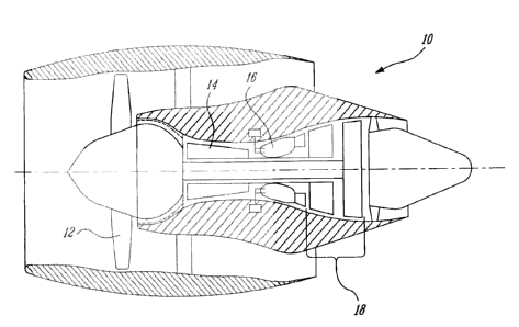
[0015] Fig. 1 illustrates a gas turbine engine 10 of a type preferably
provided for use
in subsonic flight, generally comprising in serial flow communication a fan 12
through which ambient air is propelled, a mufti-stage compressor 14 for
pressurizing
the air, a combustor 16 in which the compressed air is mixed with fuel and
ignited for
generating an annular stream of hot combustion gases, and a turbine section 18
for
extracting energy from the combustion gases.
(0016] The turbine section 18 may comprise several turbine stages, each of
which
generally includes a rotatable turbine rotor having a plurality of blades
extending
therefrom within a surrounding turbine shroud. A plurality of vanes, arranged
in an
annular configuration, are provided immediately upstream of each turbine
rotor.
(0017] Referring to prior art Fig. 2, a turbine stage 20 of a gas turbine
engine
includes generally a turbine rotor 22 having a plurality of radially extending
blades 23
and a turbine stator vane assembly 24 comprising a plurality of vanes 25
extending
between inner and outer vane platforms 27. Surrounding the turbine blades 23,
and
downstream of the stator vane assembly 24, is an annular turbine shroud 26,
which
typically comprises a plurality of individual shroud segments 28
concentrically
arranged around the periphery of the turbine blade tips. The shroud segments
28 are
supported and located within the engine by an outer housing support structure
34.
-3-


CA 02523192 2005-10-12
Spring seals 32 provide sealing between the shroud segments 28 and the
surrounding
support structure 34. While the spring seals 32 having a configuration as
depicted in
Fig. 2 provide adequate sealing properties, their relatively complex shape
makes them
expensive to manufacture. Further, additional support is required during the
shroud
grinding operations to prevent unwanted radial outward movement of the shroud
and
seals. Other shapes of ring seals are also employed elsewhere in gas turbine
engines.
For example, M-shaped seals 29 are known to be employed between the main
platforms 27 and their surrounding support structure 31 for sealing purposes
only.
[0018] Referring now to the present invention as depicted in Figs. 3 and 4, a
plurality of shroud segments 40 surrounding turbine rotor blades 23 include
axially
extending mounting platforms 41 which engage, and are preferably received
within,
corresponding mounting flange projections 45 of the surrounding shroud housing
44
in order to help locate the shroud segments 40 in position within the turbine
section
of the gas turbine engine. Internal cavities 42 are defined within the turbine
shroud
segments 40 and are generally provided with secondary cooling air via
apertures 46
defined in the surrounding housing 44. According to the present invention, M-
shaped
sealing rings 50 are wholly disposed within annular gaps 48, defined between
the
opposed surfaces of the mounting platforms 41 of the shroud segments 40 and
the
mounting flanges 45 of the surrounding housing 44. Particularly, the sealing
rings 50
are disposed between an axially extending outer surface 43 of the mounting
platforms
41 and an axially extending inner surface 49 of the surrounding shroud housing
44.
The M-shaped sealing rings 50 act to seal the shroud cavity 42 such that
leakage of
cooling air from the cavity 42 into the main gas path is at least limited, if
not
prevented. The sealing is particularly achieved by radially pinching the M-
shaped
sealing rings 50 between the axial projections 41 of the turbine shroud
segments 40
and the surrounding outer housing 44.
[0019] M-shaped sealing rings 50 are preferably provided both at the upstream
and
downstream engagement points of the shroud segments 40, between the shroud
segments and the surrounding housing. The M-shaped sealing rings 50 further
act to
load the shroud segments 40 radially inward, and thereby obviate the need for
additional shroud supports at least during the shroud grinding operation
performed
-4-


CA 02523192 2005-10-12
following assembly of the turbine section of the gas turbine engine. This
shroud
grinding step is performed in order to achieve the precise tip clearance gap
desired
between the turbine blade tips and the surrounding shroud segments, thereby
minimizing tip clearance losses. The M-shaped sealing rings 50 also have a
simplified shape in comparison with the more complex sealing rings 32 known in
the
prior art for sealing turbine shroud segments, and are therefore less costly
to produce
than the turbine shroud seals 32 of the prior art, which have a significantly
more
complex shape necessitating more forming operations.
[00201 The M-shaped sealing rings 50 may be constructed as an annular ring to
be
fitted within the annular gap 48. The M-shaped sealing rings may also be
provided
with a split therein to allow circumferential expansion if necessary.
[00211 Referring now to Fig. 4, the M-shaped sealing rings 50 comprise
preferably
three substantially evenly spaced peaks, namely two outer peaks 52 which abut
the
inner surface 49 of the outer shroud housing 44, and a central inner peak 56
which
abuts the outer surface 43 of the axial projections 41 of the shroud segments.
Thus,
the M-shaped sealing rings 50 provide radially inward loading of the shroud
segments 40 within the fixed outer housing 44. This configuration of the M-
shaped
sealing rings permits sufficient radial inward force to be exerted on the
shroud
segments 40, thus preventing unwanted outward movement thereof during the
above
described shroud grinding operation. The M-shaped sealing rings 50 therefore
provide a simple and cost effective seal which acts to load the component,
particularly to load the turbine shroud segments 40 radially inward, while
maintaining a sealing ability sufficient to prevent leakage of cooling air.
[00221 The above description is meant to be exemplary only, and one skilled in
the
art will recognize that changes may be made to the embodiments described
without
department from the scope of the invention disclosed. For example, the sealing
rings
of the present invention may be made of any material suitable for the given
application. Further, while the ring seals of the present invention are
preferably M-
shaped with three alternating peaks, they nevertheless comprise a wave pattern
having at least two alternating peaks and may include more than three while
maintaining a configuration which is cost effective to manufacture. Still
other
-5-


CA 02523192 2005-10-12
modifications which fall within the scope of the present invention will be
apparent to
those skilled in the art, in light of a review of this disclosure, and such
modifications
are intended to fall within the appended claims.
-6-

Representative Drawing
A single figure which represents the drawing illustrating the invention.
Administrative Status

For a clearer understanding of the status of the application/patent presented on this page, the site Disclaimer , as well as the definitions for Patent , Administrative Status , Maintenance Fee  and Payment History  should be consulted.

Administrative Status

Title Date
Forecasted Issue Date 2012-07-10
(22) Filed 2005-10-12
(41) Open to Public Inspection 2006-04-15
Examination Requested 2008-06-25
(45) Issued 2012-07-10

Abandonment History

Abandonment Date Reason Reinstatement Date
2007-10-12 FAILURE TO PAY APPLICATION MAINTENANCE FEE 2008-05-08

Maintenance Fee

Last Payment of $473.65 was received on 2023-09-20


 Upcoming maintenance fee amounts

Description Date Amount
Next Payment if standard fee 2024-10-14 $624.00
Next Payment if small entity fee 2024-10-14 $253.00

Note : If the full payment has not been received on or before the date indicated, a further fee may be required which may be one of the following

  • the reinstatement fee;
  • the late payment fee; or
  • additional fee to reverse deemed expiry.

Patent fees are adjusted on the 1st of January every year. The amounts above are the current amounts if received by December 31 of the current year.
Please refer to the CIPO Patent Fees web page to see all current fee amounts.

Payment History

Fee Type Anniversary Year Due Date Amount Paid Paid Date
Registration of a document - section 124 $100.00 2005-10-12
Application Fee $400.00 2005-10-12
Reinstatement: Failure to Pay Application Maintenance Fees $200.00 2008-05-08
Maintenance Fee - Application - New Act 2 2007-10-12 $100.00 2008-05-08
Request for Examination $800.00 2008-06-25
Maintenance Fee - Application - New Act 3 2008-10-14 $100.00 2008-08-22
Maintenance Fee - Application - New Act 4 2009-10-13 $100.00 2009-10-08
Maintenance Fee - Application - New Act 5 2010-10-12 $200.00 2010-10-12
Maintenance Fee - Application - New Act 6 2011-10-12 $200.00 2011-09-14
Final Fee $300.00 2012-04-19
Maintenance Fee - Application - New Act 7 2012-10-12 $200.00 2012-04-19
Maintenance Fee - Patent - New Act 8 2013-10-15 $200.00 2013-09-13
Maintenance Fee - Patent - New Act 9 2014-10-14 $200.00 2014-09-17
Maintenance Fee - Patent - New Act 10 2015-10-13 $250.00 2015-09-24
Maintenance Fee - Patent - New Act 11 2016-10-12 $250.00 2016-09-21
Maintenance Fee - Patent - New Act 12 2017-10-12 $250.00 2017-09-20
Maintenance Fee - Patent - New Act 13 2018-10-12 $250.00 2018-09-21
Maintenance Fee - Patent - New Act 14 2019-10-15 $250.00 2019-09-20
Maintenance Fee - Patent - New Act 15 2020-10-13 $450.00 2020-09-17
Maintenance Fee - Patent - New Act 16 2021-10-12 $459.00 2021-09-21
Maintenance Fee - Patent - New Act 17 2022-10-12 $458.08 2022-09-22
Maintenance Fee - Patent - New Act 18 2023-10-12 $473.65 2023-09-20
Owners on Record

Note: Records showing the ownership history in alphabetical order.

Current Owners on Record
PRATT & WHITNEY CANADA CORP.
Past Owners on Record
BLAIS, DANY
SYNNOTT, REMY
Past Owners that do not appear in the "Owners on Record" listing will appear in other documentation within the application.
Documents

To view selected files, please enter reCAPTCHA code :


To view images, click a link in the Document Description column. To download the documents, select one or more checkboxes in the first column and then click the "Download Selected in PDF format (Zip Archive)" or the "Download Selected as Single PDF" button.

List of published and non-published patent-specific documents on the CPD .

If you have any difficulty accessing content, you can call the Client Service Centre at 1-866-997-1936 or send them an e-mail at CIPO Client Service Centre.


Document
Description 
Date
(yyyy-mm-dd) 
Number of pages   Size of Image (KB) 
Description 2005-10-12 6 265
Abstract 2005-10-12 1 10
Claims 2005-10-12 4 123
Drawings 2005-10-12 3 156
Representative Drawing 2006-03-20 1 31
Cover Page 2006-04-06 1 55
Claims 2011-05-26 4 125
Cover Page 2012-06-14 1 56
Assignment 2005-10-12 9 282
Correspondence 2008-03-04 1 20
Correspondence 2008-03-04 1 14
Correspondence 2008-02-05 2 64
Fees 2008-05-08 2 64
Prosecution-Amendment 2010-12-14 2 64
Prosecution-Amendment 2008-06-25 2 68
Prosecution-Amendment 2011-05-26 8 281
Correspondence 2012-04-19 2 65