Note: Descriptions are shown in the official language in which they were submitted.
CA 02523382 2005-10-21
WO 2004/100115 PCT/NZ2004/000085
1
IMPROVEMENTS RELATING TO BILLBOARDS
FIELD OF THE INVENTION
The present invention relates to billboards for displaying images and in
particular to
billboards for displaying images that appear to a viewer to be 3D.
BACKGROUND OF THE INVENTION
3D, animation and flip technology is currently implemented using a lenticular
lens
disposed in front of an interlaced image print. US 5,847,808 provides a
general
indication of the technology. The print is created using software that takes
"slices" or
"strips" of several images and interlaces them using an offset press or a
digital printer.
The print is applied directly to the back of the lenticular lens, such that
the interlaced
portions are aligned with the lenticles of the lens. The lenticular lens
obscures a subset
of the interlaced strips when viewed from a particular angle, such that a
composite
image is seen, comprising strips originating from one or more of the
interlaced images.
As the viewer angles shifts, other strips are obscured presenting another
composite
image to the viewer.
Where the print comprises strips from multiple images of different layers of
an object, a
3D effect is achieved. In this context, 3D means the viewer perceives that the
image has
depth, when viewed at various angles. Flip and animation technology operates
in a
similar manner, wherein several interlaced sequential images are provided on
the print,
and the viewer sees each in sequence as they view at different angles. This
produces the
perception of animation-or flipping, if only two images are used. A similar
affect can
be produced using a barrier, instead of a lenticular lens, such as shown in US
5,695,346
and US 4,927,238. In this case, the black barrier lines obscure certain
portions of the
interlaced print at particular angles.
While existing technology can be used to display billboard sized 3D images,
animations
and flips, it is a relatively difficult and costly exercise due to the
limitations of the
CA 02523382 2005-10-21
WO 2004/100115 PCT/NZ2004/000085
2
technology. For example, the largest lenticular lens available is 2.5m by
1.2m.
Therefore, to provide a billboard sized display, multiple lenses and prints
must be
combined.
SUMMARY OF THE INVENTION
It is an object of the invention to provide an apparatus that can display
billboard sized
images that axe perceived as 3D.
In one aspect the present invention comprises an apparatus for displaying
images
including: an enclosure, a frame installed in the enclosure and adapted to
hold an
interlaced image, and an optical barrier spaced from the frame and adapted to
obscure
portions of an installed interlaced image.
Preferably, the apparatus further includes an image installed in the frame.
The image is
a composition of multiple interlaced images.
Preferably, the interlaced images in conjunction with the optical barrier
display 3D
images to a viewer.
In one embodiment the image is applied to a single piece of translucent
material.
Preferably, the optical barrier includes a plurality of elongated grills. The
grills may be
extruded from a non-reflective material, such as anodised aluminium.
Preferably, the
grills have a triangular or circular segment cross-section.
Preferably, the grills are arranged adjacently in a linear array, oriented
vertically, with a
gap between adjacent grills. Preferably, the grills are spaced such that there
is a ratio of
80/20 of grill width to gap. Most preferably, the width of each grill is 20.32
mm wide,
and the gap between each grill is 5.08 mm wide to provide viewing between the
angles
of 15-165°.
CA 02523382 2005-10-21
WO 2004/100115 PCT/NZ2004/000085
3
Preferably, the enclosure is adapted to house a light source to provide back
lighting for
an image installed in the frame. The light source may be a plurality of
fluorescent
lights, for example. Preferably the enclosure is constructed from non-
reflective, opaque
material.
Preferably, the space between the image frame and optical barrier is
adjustable, either
manually or automatically. This may be by way of a suitable mechanical or
electromechanical adjustment system, such as telescopic or slidable spacers.
This can
alter the perceived depth of a displayed image, and/or ensure the desired
optical effect is
achieved by the apparatus.
Preferably, the relative horizontal and vertical position of the image frame
and optical
barrier is adjustable, either manually or automatically. This may be by way of
a suitable
mechanical or electromechanical adjustment system. This may be to align the
interlaced image with the grills of the barrier, and/or ensure the desired
optical effect is
achieved by the apparatus.
Preferably the enclosure can be tilted to provide optimum viewing.
BRIEF DESCRIPTION OF THE DRAWINGS
Preferred embodiments of the invention will be described with reference to the
accompanying drawings, of which:
Figure 1 shows a preferred embodiment of an assembled billboard for displaying
images according to the invention,
Figure 2 shows and exploded view of the billboard, including a image frame and
optical barrier,
Figure 3 shows a cross-sectional view of the billboard viewed from point A in
Figure 1,
Figure 4 shows a cross-sectional view of the billboard viewed from point B in
Figure 1,
CA 02523382 2005-10-21
WO 2004/100115 PCT/NZ2004/000085
4
Figure SA shows one embodiment of the optical barrier in relation to the image
in more detail,
Figure SB shows another embodiment of the optical barrier in relation to the
image in more detail, and
Figures 6A-6D show an example of a interlaced image in relation to the optical
barrier.
DETAILED DESCRIPTION OF THE PREFERRED EMBODIMENTS
Figure 1 shows a preferred embodiment of a billboard 10 according to the
invention in
assembled form. The term "billboard" is used throughout the specification to
refer to a
structure which displays an image. While the structure of the present
invention is not a
billboard in the traditional sense, it can be used to display images of a size
and nature
typically displayed by traditional billboards. For example, it can display
images which
are 6m by 3m or larger in size.
In the preferred embodiment, the billboard 10 is adapted to display 3D images.
The
billboard 10 includes an opaque enclosure 11, constructed from a base (not
visible in
Figure 1) and four sides. An optical barrier 12 covers the enclosure 11.
Preferably the
optical barrier 12 is formed by a plurality of opaque grills, eg 14, supported
in a
rectangular frame 15. The image displayed by billboard 10 is viewed through
optical
barrier 12. The structure 10 forms a light box which substantially restricts
light entering
or escaping. Typical overall dimensions of a billboard are 6.5 m x 3.5 m with
greater
sizes generally seeing a disproportionate increase in the longitudinal
dimension.
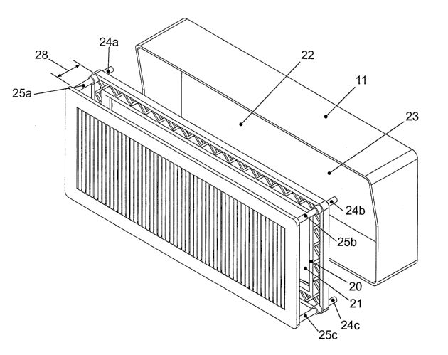
Figures 2 to 4 show internal components of the billboard 10. A image frame 20,
adapted to hold a image 21, is disposed in the interior 22 of the enclosure
11.
Preferably, the image frame is constructed of steel or similar, and has a non-
reflective
border with a width of approximately 10% to 20% of the length of the image 21,
to
enhance viewing. Alternatively different frame widths may be used. The image
21 is a
composition of multiple interlaced images. In one embodiment the image is
applied to a
single piece of suitable light transparent or translucent image material, such
as specified
CA 02523382 2005-10-21
WO 2004/100115 PCT/NZ2004/000085
backlit canvas or the like. The image 21 can be stretched over and installed
on the
frame 20, and a mechanical tension locking system (not shown) holds the image
21 taut.
The image frame 20 is spaced from the back wall 23 of the enclosure 11 by four
spacer
rods, of which three 24a-24c are visible in Figure 2. The spacer rods 24a-24d
are
5 interconnected between the frame 20 and the back wall 23 of enclosure 11 by
any
suitable means known in the art. The optical barrier 12 is attached to and
spaced 28
apart from the image frame 20, by four spacer rods, of which three, 25a-25c
are visible.
In one embodiment, the interior 23 of the enclosure 11 behind the image frame
20
houses a suitable light source (shown in Figures 3 and 4) to back light the
image 21.
The light source could be, for example, an array of fluorescent lights 30 as
shown in
Figures 3 and 4. Illuminating the image 21 in this manner, enables a printed
image to
be viewed through the optical barrier 12. An overhang 27 provides some
shielding of
the front of the enclosure from ambient light to improve viewing conditions.
Preferably, the entire structure can be tilted to optimise viewing.
Figure 3 is a side view of the billboard viewed from point A in Figure 1. This
Figure
shows the spatial relationship between the grid, image and back lights in more
detail.
As can be seen the image 21 is spaced from grid 12 by spacers 25b and 25c. The
image
is also separated from the back of enclosure 11 by spacers 24b and 24c. Lights
30 are
positioned between image 21 and the back of enclosure 11 to back light image
21.
Figure 4 is a view of the billboard viewed from point B in Figure 1. Again the
alignment of the optical barrier 12, image 20 spacers 24a, b, 25a, b, and
lights 30 can be
seen within enclosure 11. This Figure shows that optical barrier 12 includes a
plurality
of grills 14 surrounded by frame 15.
In the embodiments described above the image is provided on print 21. In
alternative
embodiments the image may be provided on other viewing media. Such media
include
rear projection of the image onto a screen or an outdoor television screen.
When images
are displayed on these media a light box behind the screen may not be needed.
These
CA 02523382 2005-10-21
WO 2004/100115 PCT/NZ2004/000085
6
viewing media also allow the image to be easily changed. For example a
billboard of
the invention may be used to sequentially display a plurality of images.
Figures 4 and SA and B show a section the optical barrier 12 in further
detail. In these
Figures the barrier 12 includes a plurality of elongated grills, eg 14, with a
triangular or
circular segmented cross-section. For example, the front face of each grill is
flat or
curved, and the back is angled so that the vertex of the grill faces the
image. The grills
14 are arranged in a linear array, each extending vertically from the top of
the frame 15
to the bottom. The frame 15 is preferably non-reflective and in preferred
embodiments
has a width of approximately 200 mm to 300 mm to enhance the displayed image.
Each
grill 14 is constructed from stiff non-reflective material, such as anodized
aluminium
extrusion. The non-reflective qualities reduce reflection of ambient light
during the day,
which hampers visibility of the image 21.
In alternative embodiments the grills may be any shape that provides a
changing view as
a passer-by walks past the billboard. Ideally, the portion of the grills
closest to the
image has a smaller width than the portion of the grills closest to a passer-
by. For
example the grills may be a "T" shape with the top of the T closest to a
passer-by and
the leg of the T extending towards the image. Ideally the design of the grill
will
maximise the viewing angle of the image. The grill should also be designated
to
minimise reflection from the grill, maximise the strength of the grill, and
minimise
movement of the grill. Reflection from the grill can be minimised in a number
of ways
including by matt black coating at least any surface of the grill visible to a
passer-by or
by pitting at least any surface of the grill visible to a passer-by. The
strength of the grill
can be maximised by forming the grill from stiff material. Additional strength
can be
obtained by running high-tensile wires through the inside of any hollow grill
pieces.
Movement of the grill can be minimised by high tensile wires inside hollow
grill pieces.
Additionally it may be possible to run high tensile wires horizontally behind
and/or
through grill pieces to further prevent movement of the grill in outdoor
conditions.
The adjacent grills 14 are arranged to provide a gap 50 between each pair of
grills,
through which portions of the image 21 can be viewed by a passer-by.
Preferably,
CA 02523382 2005-10-21
WO 2004/100115 PCT/NZ2004/000085
7
there is an 80/20 grill width to spacing 50 ratio, although a variance of up
to 5% can be
tolerated. In Figure SA this ratio is the ratio of A to C where B is the width
of the grill
14 and gap 50. For example, in the preferred embodiment each grill 14 has a
width of
20.23 mm and the gap 50 between each grill is 5.08 mm. As will be appreciated,
other
dimensions that retain the substantially 80/20 ratio of grill width to space
50 could be
used.
As can be seen in Figure SA, the triangle rear portion of each grill 14
enables a passer
by to view the image over a 150° field view. By varying the width and
breadth of the
grills 14 the viewing angle can be changed. For example the viewing angle y
provided
by the grills of Figure SA is between 55° and 125° giving a
complete viewing angle of
70°. In Figure SB the width to breadth ratio of the grill 14 has
increased giving a wider
viewing angle. In Figure SB the viewing angle 'y is between 40° and
140° giving a
viewing angle of 100°. In these Figures the image is obscured at view
angles cp and A.
If the grills are 20.23 mm with a between grill spacing of 5.08 mm and
suitable grill
breadth a viewing angle of 165° can be obtained. If a passer-by is
outside the viewing
angle the image will be obscured, by grid 12. For the best viewing performance
the grill
pieces 14 must remain parallel to each other and equidistant from the image
21. The
grill pieces must be formed of a material that will resist movement under wind
loading
and other outdoor conditions.
Figures 6A to 6D show an example of an interlaced image 21 according to the
invention. The image 21 is shown in both elevation and plan to illustrate its
relationship
with the optical barner 12. Each image forming the image 21 is divided into
pixel
strips, eg 60. The first strip from each image is arranged adjacently in the
image 21, and
this forms one "set". A set may contain any number of strips but in preferred
embodiments between 10 and 25 strips make up each set. The number of sets
depends
upon the number of grills in the billboard. For example, where ten images form
the
interlaced image 21, each set comprises 10 strips, one from each image. The
second set
is formed from the second strip of each of the 10 images, and arranged
adjacently to the
first set. This process is carried out for the third and subsequent sets,
resulting in an
entire image 21 assembled from adjacently placed sets of image slices. The
forming
CA 02523382 2005-10-21
WO 2004/100115 PCT/NZ2004/000085
8
images into strips and sets can be performed on a computer before the image is
printed
or otherwise displayed.
One set 61 from the image 21 can be seen in Figure 6A. The width of the set 61
matches the width of one grill 14 plus the gap 50 to an adjacent grill. For
the preferred
embodiment, this width is 25.4 mm or 1 inch. Each of the 10 strips forming the
set 61
have a width that is one tenth of this total, namely 2.54 mm. All the sets 61
should be
aligned with corresponding grills 14. If they are not, as shown in Figure 6b,
the relative
positions of the barrier 12 and image 21 should be adjusted from an unaligned
position
62, to an aligned position 63.
As will be appreciated, a different number of images may form the interlaced
image 21,
which will result in a different number of strips forming each set 61. For
example, any
number between 10 and 25 images may be used in a image 21, resulting in a
corresponding number of slices per set 61. In each case, the total set 61
width will
match the width of a grill 14 plus gap 50, and therefore the width of
individual strips
must be adjusted accordingly. Where the billboard 11 displays objects in 3D,
each
image forming the image 21 relates to a different layer of the 3D objects.
Where the
billboard displays animations or flips, each image in the image 21 relates to
one image
in the animation/flip sequence. The interlaced image 21 could be created from
individual images using interlacing software. When displaying an image in 3D
the use
of the different layers provided by each image give the whole image an
appearance of
depth thus providing the 3D effect.
Various additional features can be implemented in the basic billboard 10. The
image
frame 20 and optical barrier 12 could be connected by adjustable spacers 24a-
24c to
facilitate adjustment of the gap 28. For example, the spacer rods 24a-24c may
be
telescopic or slidable, such that they can manually or automatically extended
or
retracted to adjust the gap. Alternatively, any other suitable manual or
automatic
mechanical or electromechanical adjustment system could be installed.
Similarly, the
vertical and horizontal position of the image frame 20 and/or barrier 12 could
be
adjusted by a manual or electromechanical means to align the image 21
correctly with
CA 02523382 2005-10-21
WO 2004/100115 PCT/NZ2004/000085
9
the grills 14 of the optical barrier 12. Correct alignment between the sets 61
of the
image 21 and grills 14 of the optical barrier 12 is important to ensure the
desired optical
effect is achieved. Deliberate movement of the image 21 and/or barrier 12, can
however
create a desirable animation effect. Preferably, lateral movement is no
greater than the
width of a grill 14. For example, one option is to use an electric motor to
adjust the
image laterally and/or horizontally by up to 20 mm to 30 mm.
If the image is printed the image material itself may stretch somewhat when
installed on
the image frame 20 depending on the particular properties and composition of
the image
material and the anticipated ambient conditions. It may be necessary to assess
this
stretch in both the longitudinal and transverse directions and compensate for
it, to
ensure correct alignment. A mathematical stretch analysis of the image medium
can be
carried out, and this analysis is used when producing the image 21 to ensure
stretch of
the material is taken into account and the resultant interlacings are
correctly
proportioned within the permissible tolerances. The printing process
preferably uses a
higher resolution than standard billboard printing, and the amount of ink
printed onto
the material is doubled in density to make it light durable, and to avoid
colour blowout.
If the image is displayed using other media stretch analysis may not be
needed.
A displayed 3D image may have an apparent depth of between 60%-100% of the
billboard width, depending on the images used and background layer of the
image 21.
This is a perceived depth, not actual, and may differ from person to person.
The
perceived depth of a 3D image displayed by the billboard 10 can be changed by
altering
the distance 28 (shown in Figure 6C) between the optical barrier 12 and image
21.
Altering the gap 28 also ensures the correct optical effect is achieved. The
distance 28
between the frame 20 and barrier 12 is calculated to give the desired image
clarity, 3D
effect, and depth of image. For example, as shown in Figure 6C, there is a
wider
viewing angle 65 when the gap 28 between the optical barrier 12 and image 21
is
increased by moving the barrier 12 from position A to position B. This is due
to the
increased angles of line of sight 66 from the viewer's eye 67, through the
gaps in the
barrier 12, to the image 21. As a result, different subsets of the strips 60
are view, and
the viewer 67 perceives a greater depth in the displayed image. As shown in
Figure 6D,
CA 02523382 2005-10-21
WO 2004/100115 PCT/NZ2004/000085
if the barrier 12 is moved closer to the image 21, from position B to position
A, there is
a narrower viewing angle 69, due to the decreased angles of line of sight 70.
Different
slices of the images making up the image 21 are blocked, than in Figure 6C.
Those
slices seen by the viewer form a composite image, which has a shallower depth
than for
5 the image viewed in Figure 6C. Similarly, as the viewer moves laterally in
front of the
optical barrier 12, the angle of their lines of sight through the barrier 12
also changes.
This results in a different subset of strips in each set being obscured by the
barrier 12,
causing the viewer to see a different composite image formed from the strips.
In the
case of a 3D image 21, the viewer will perceive that they are viewing the
displayed
10 image at different angles, when moving laterally.
Various additional features can optionally be implemented with the invention.
'The
frame 20 can be unlocked and moved back, for example by 500 mm, to permit
access to
change the image 21 or conduct maintenance or the like. Components of the
structure
10 are preferably constructed from materials with similar thermal expansion co-
efficients to reduce uneven expansion. Doors and access ways can be included
in the
billboard 10 to facilitate maintenance and changing of images. Sensors to
detect
temperature, humidity and light remotely could be installed to monitor
conditions.
Drainage facilities in the billboard could be included. Additional lighting
could be
included in the billboard to accentuate the image and ensure adequate light
distribution.
The foregoing describes the invention including preferred forms thereof.
Alterations
and modifications as will be obvious to those skilled in the art are intended
to be
incorporated in the scope hereof as defined by the accompanying claims.