Note: Descriptions are shown in the official language in which they were submitted.
CA 02523403 2005-10-24
WO 2004/096345 PCT/US2004/011649
-1-
CARDIAC PACING FOR OPTIMAL INTRA-LEFT VENTRICULAR
RESYNCHRONIZATION
This disclosure relates to implantable medical devices and more particularly
to
implantable cardiac pacemakers used to treat ventricular dysynchrony.
Heart failure affects approximately 5 million people in the United States.
Many
moderate to severe heart failure patients may also have a condition in which
the two lower
chambers of the heart (known as the left and right ventricles) are not beating
together as they
do normally. In medical terms, this condition is called "ventricular
dysynchrony."
Ventricular dysynchrony disturbs the synchronous beating of the heart, and as
a result the
heart does not pump blood adequately to meet the needs of the body. More
specifically,
ventricular dysynchrony typically results from intraventricular conduction
delays (IVCD) that
disturb the synchronous beating of the ventricles. Typically, the IVCD has a
left bundle
1 S branch block (LBBB) morphology.
One previous method for optimizing cardiac pacing for infra-left ventricular
resynchronization involves modifying pacing to reduce QRS duration. Even
though QRS
duration can be reduced, reduction in QRS duration does not guarantee optimal
hemodynamic cardiac operation. Kass et al., Improved left ventricular
mechanics from acute
IlDD pacing in patients with dilated cardiomyopathy and ventricular conduction
delay,
Circulation 1999; 99:1567-73.
Another previous method for optimizing cardiac pacing for infra-left
ventricular
resynchronization involves modifying pacing to improve.cardiac ventricle
filling. Typically
cardiac ventricle filling is measured by echocardiography. Although cardiac
filling is one
aspect of hemodynamics, tests have shown that optimal hemodynamic cardiac
operation by
pacing does not result from better cardiac filling. Auricchio et al., Cardiac
resynchronizatioya
therapy restores optimal atrioventricular mechanical timing in heart failure
patients with
ventricular conduction delay, J. Am Coll Cardiol 2002; 39:1163-9.
One therapy to treat left ventricle dysynchrony is Cardiac Resynchronization
Therapy
(CRT). CRT is a new, proven treatment for selected patients with heart failure-
induced
conduction disturbances and ventricular dysynchrony. When used in combination
with
stable, optimal medical therapy, CRT is designed to reduce symptoms by
restoring the
CA 02523403 2005-10-24
WO 2004/096345 PCT/US2004/011649
-2-
mechanical sequence of ventricular activation. Cardiac resynchronization
therapy (CRT)
provides atrial-synchronized, biventricular pacing using standard pacing
technology
combined with a special third lead which is implanted via the coronary sinus
and positioned
in a cardiac vein to sense and pace the left ventricle. Following a sensed
atrial contraction,
both ventricles are stimulated to contract more synchronous. The resulting
resynchronization
of ventricular contraction reduces mitral regurgitation and optimizes left
ventricular filling,
thereby improving cardiac function.
Cardiac pacing for optimal infra-left ventricular resynchronization is
performed as
follows. Early paced inter-ventricular asynchrony is determined during
ventricular pacing.
Baseline inter-ventricular asynchrony is determined without pacing. Average
inter-
ventricular asynchrony is calculated by averaging the early paced inter-
ventricular
asynchrony and the baseline inter-ventricular asynchrony. Atrio-ventricular
delay and
ventricular-ventricular delay are adjusted during ventricular pacing to yield
the average inter-
ventricular asynchrony for optimal infra-left ventricular resynchronization.
The elements
above can be configured in software contained in an implantable medical device
or embodied
as a computer software product that includes a medium readable by a processor.
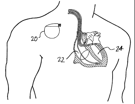
FIG. 1 shows an environmental view of an implantable cardiac device (ICD).
FIG. 2 shows a more detailed environmental view of an ICD.
FIG. 3 shows a simplified block diagram of an ICD.
FIG. 4 shows a flowchart of a method for cardiac pacing for optimal infra-left
ventricular resynchronization.
FIG. 5 shows a flowchart of a method for adjusting atrio-ventricular delay and
ventricular-ventricular delay.
FIG. 6 shows a chart relating atrio-ventricular delay, infra-ventricular
asynchrony, and
inter-ventricular asynchrony during left ventricular pacing.
FIG. 7 shows bulls-eye plots of left-ventricular (LV) endocardial activation
times
during left bundle branch block (LBBB)+LV later wall pacing.
FIG. 8 shows a graph of inter-ventricular asynchrony (interVA) as a function
of the
atrio-ventricular delay (AV-delay) during left bundle branch block (LBBB) +
left ventricle
(LV) pacing.
CA 02523403 2005-10-24
WO 2004/096345 PCT/US2004/011649
-3-
FIG. 9 shows a flowchart of optimization of interventricular asynchrony
(interVA) for
maximal hemodynamic effect during left-ventricle (LV) pacing.
FIG. 10 shows a flowchart of an alternative approach to maximize hemodynamic
effect of left-ventricular (LV) pacing.
FIG. 11 shows a flowchart of optimization of interventricular asynchrony
(interVA)
for maximal hemodynamic effect during bi-ventricular (BiV) pacing.
FIG. 12 shows a graph of the relative change in LVdP/dt~max in percent during
left
ventricle (LV) and bi-ventricle (BiV) pacing in a canine heart with left
bundle branch block
(LBBB).
FIG. 13 shows a graph of inter-ventricular asynchrony (interVA) during bi-
ventricular
(BiV) pacing versus the average interVA during left ventricle (LV) and right
ventricle (RV)
pacing for all atrio-ventricular delays (AV-delays).
FIG. 14 shows three dimensional graph of the relationship between
interventricular
asynchrony (interVA) during bi-ventricular (BiV) pacing as a function of atrio-
ventricular
delay (AV-delay) and ventricular ventricular interval (VV-interval).
FIGS. 1 and 2 show an environmental view of an Implantable Cardiac Device
(ICD)
for optimal infra-left ventricular resynchronization. The ICD can be any ICD
capable pacing
both the right ventricle and the left ventricle known as bi-ventricular
pacing. Implantable
Cardiac Devices suitable for bi-ventricular pacing include certain pacemakers,
cardioverters,
and defibrillators configured for bi-ventricular pacing. For example, the ICD
and be an
InSync~ III Model 8040 pacemaker or an InSync~ Marquis
cardioverter/defibrillator using
two standard right heart electrical leads (in the right atrium and right
ventricle) and one left-
heart electrical lead such as an AttainTM Model 2187, 2188 or 4193 also
available from
Medtronic, Inc. in Minneapolis, Minnesota USA. The left heart electrical lead
is typically
implanted transvenously via the coronary sinus and positioned in a cardiac
vein to pace the
left ventricle.
FIG. 3 shows a block diagram of an implantable cardiac device 20 for optimal
intra-
left ventricular resynchronization. The cardiac pacemaker 20 comprises a
housing 26, a
controller 28, memory 30, pacing electronics 32, sensing electronics 34, a
first electrical lead
36, a second electrical lead 38, and software 40. The housing 26 has a power
supply 42
carried in the housing 26 and a feedthrough 44. The controller 28 is carried
in the housing 26
CA 02523403 2005-10-24
WO 2004/096345 PCT/US2004/011649
-4-
and coupled to the power supply 42. Memory 30 is coupled to the controller 28.
The pacing
electronics 32 are coupled to the controller 28 and the feedthrough 44. The
sensing
electronics 34 are coupled to the controller 28 and the feedthrough 44.
The first electrical lead 36 is coupled to the feedthrough 44 and configured
for
positioning in the right ventricle 22. The first electrical lead 36 has at
least a first electrode
for pacing the right ventricle 22, and the first electrical lead 36 can also
have additional
electrodes for functions such as pacing the right atrium. The first electrode
can also serve as
a sensing electrode to provide sensing signals of right ventricle 22 timing to
the sensing
electronics 34.
The second electrical lead 38 is coupled to the feedthrough 44 and configured
for
positioning in the left ventricle 24. The second electrical lead 38 has at
least a second
electrode for pacing the left ventricle 24, and the second electrical lead 38
can also have
additional electrodes for functions such as pacing the left atrium. The second
electrode can
also serve as a sensing electrode to provide sensing signals of left ventrical
24 timing to the
sensing electronics 34.
In addition to sensors placed on the first electrical lead 36 and second
electrical lead
38, a variety of other electrical or mechanical sensors can be used to sense
asynchronies such
as a vectorcardiogram, bodysurface mapping, echocardiography, heartsounds,
tissue Doppler
Imaging, and the like.
Software 40 is stored in memory 30 that contains a first sequence of
instructions 46, a
second sequence of instructions 48, a third sequence of instructions 50, and a
fourth sequence
of instructions 52. The software 40 can be configured in the implantable
medical device 20
or embodied as a computer software product that includes a medium readable by
a processor.
The first sequence of instructions 46 when executed by the controller 28,
causes the
controller 28 to receive early paced inter-ventricular asynchrony data during
ventricular
pacing through the first electrical lead 36 and sensing electronics 34. The
first sequence of
instructions 46 serves as a means for determining paced inter-ventricular
asynchrony during
ventricular pacing. The second sequence of instruction 48 when executed by the
controller
28, causes the controller 28 to receive baseline inter-ventricular asynchrony
without pacing
data through the first electrical lead 36, the second electrical lead 38, and
sensing electronics
34. The second sequence of instructions 48 serves as a means for determining
baseline inter-
CA 02523403 2005-10-24
WO 2004/096345 PCT/US2004/011649
-5-
ventricular asynchrony without pacing. The third sequence of instruction 50
when executed
by the controller 28, causes the controller 28 to calculate average inter-
ventricular
asynchrony by averaging the early paced inter-ventricular asynchrony data and
the baseline
inter-ventricular asynchrony data. The third sequence of instructions 50
serves as a means
for calculating average inter-ventricular asynchrony by averaging the paced
inter-ventricular
asynchrony and the baseline inter-ventricular asynchrony. The forth sequence
of instructions
52 when executed by the controller 28, causes the controller 28 to adjust
atrio-ventricular
delay and ventricular-ventricular delay during ventricular pacing to yield the
average inter-
ventricular asynchrony for optimal infra-left ventricular resynchronization.
The forth
sequence of instructions 52 serves as a means for adjusting atrio-ventricular
delay and
ventricle-ventricle delay during ventricular pacing to yield the average inter-
ventricular
asynchrony for optimal infra-left ventricular resynchronization.
FIG 4. shows a flowchart of a method for cardiac pacing for optimal infra-left
ventricular resynchronization. The implantable cardiac device 20 such as a
pacemaker
operates by performing a method for optimal infra-left ventricular
resynchronization that
comprises the elements of determining early paced inter-ventricular asynchrony
54,
determining baseline inter-ventricular asynchrony 56, calculating average
inter-ventricular
asynchrony 58, and adjusting delay during ventricular pacing 60. The
implantable cardiac
device 20 can perform infra-left ventricular resynchronization optimization
automatically or
through the control of a clinician. The early paced inter-ventricular
asynchrony is determined
54 during ventricular pacing. The early paced inter-ventricular asynchrony is
determined 54
by applying the short atrio-ventricular delay and then measuring the
activation delay between
the left-ventricle 22 and the right-ventricle 24. The short atrio-ventricular
delay is less than
50 ms. The baseline inter-ventricular asynchrony is determined 56 without
pacing. The
baseline inter-ventricular asynchrony is determined 56 by measuring the
activation delay
between the right-ventricle 22 and the left-ventricle 24. The average inter-
ventricular
asynchrony is calculated 58 by averaging the early paced inter-ventricular
asynchrony 54 and
the baseline inter-ventricular asynchrony 56. The average inter-ventricular
asynchrony 58
optimizes cardiac function by minimizing infra-left ventricular asynchrony.
FIG. 5 shows a flowchart of a method for adjusting atrio-ventricular delay and
ventricular-ventricular delay. The atrio-ventricular delay and ventricular-
ventricular delay
CA 02523403 2005-10-24
WO 2004/096345 PCT/US2004/011649
-6-
are adjusted during ventricular pacing to yield the average inter-ventricular
asynchrony for
optimal infra-left ventricular resynchronization. The atrio-ventricular delay
and ventricular-
ventricular delay are adjusted by adjusting atrio-ventricular delay 62,
measuring the inter-
ventricular asynchrony 64, comparing the inter-ventricular asynchrony 66,
adjusting atrio-
ventricular delay 68, and setting the atrio-ventricular delay 70. The atrio-
ventricular delay 62
is adjusted by an atrio-ventricular delay increment. The ventricular-
ventricular delay can be
increased or decreased by a ventricular-ventricular delay increment. The inter-
ventricular
asynchrony is measured 64 using a sensor such as a left-ventricular pacing
lead and a right-
ventricular pacing lead. The inter-ventricular asynchrony is compared 66 to
the average
inter-ventricular asynchrony. The inter-ventricular asynchrony is compared 66
to the average
inter-ventricular asynchrony by minimizing the absolute difference between the
inter-
ventricular asynchrony and the average inter-ventricular asynchrony. The atrio-
ventricular
delay is adjusted 68 by an atrio-ventricular delay increment and increasing
ventricular-
ventricular delay by a ventricular-ventricular delay increment. The atrio-
ventricular delay
increment and the ventricular-ventricular delay increment are typically less
than about 30 ms.
The atrio-ventricular delay and ventricular-ventricular delay is set once the
average inter-
ventricular asynchrony is reached.
FIG. 6 shows a chart relating atrio-ventricular delay, infra-ventricular
asynchrony, and
inter-ventricular asynchrony during left ventricular pacing. The upper panel
shows intrinsic
(also known as endogenous) left ventricle (LV) pacing induced impulse
propagation during
left bundle branch block (LBBB) + LV pacing. The middle and lower panel show
the
relation between paced AV-delay and infra-ventricular asynchrony and inter-
ventricular
asynchrony during LBBB+LV pacing.
Table 1 data was used to develop the relationships shown above in FIG. 6.
Table 1
below shows hemodynamic and asynchrony parameters before and after creation of
LBBB
and during LBBB+LV pacing for all experiments. Table 1 shows LBBB
significantly
decreased LVdP/dt~max and SW while intraVA and interVA significantly
increased. During
LBBB + optimal LV pacing LVdP/dt~maX and SW restored when pacing with an AV-
delay
equal to the baseline PQ-time. At the optimum hemodynamic response, intraVA
was
restored to pre-LBBB values while a significant residual interVA remained
present.
Table I, Hemodyraamic and Asynchrony Parameters
CA 02523403 2005-10-24
WO 2004/096345 PCT/US2004/011649
_7_
pre-LBBB post-LBBB LBBB+LVP
LVdP/dt~max[mmHg/s] 1627644 1345t413* 1929815'[
SW [ml] 34801062 1972t635* 3224950'[
interVA [ms] -6f9 -28~9* -1810*'[
intraVA [ms] St2 18t3* 4~2~
PQ-time~~BBB-AV-delay- - 1~6
[ms]
*,~ vs. pre and post. (P<0.05)
LBBB resp
In FIG. 6, the data graphed is from one animal experiment with the solid lines
showing the following conceptual relationship. I: LBBB+LV pacing at short AV-
delays; the
ventricles are completely activated by pacing induced activation resulting in
a fixed degree of
intraVA and interVA (X). II: LBBB (or LBBB+LV pacing with long AV-delays);
endogenous activation entirely determines ventricular activation resulting in
a fixed degree of
intraVA and interVA (Y). III: LBBB+LV pacing at intermediate AV-delays
(ranging from A
and B); fusion between pacing induced and endogenous activation. Minimal
intraVA occurs
when pacing induced and endogenous activation meet halfway. This results in a
residual
degree of interventricular asynchrony equal to (X+y)/2 which occurs at an AV-
delay equal to
(A+B)/2.
Based on the results from animal experiments on asynchrony during pacing, a
model
for the behavior of asynchrony as a function of the timing of pacing was
developed. With this
model, the degree of residual inter-ventricular asynchrony at the optimal
cardiac pump
function can be predicted. This allows for optimization of pacing therapy
based on
measurements of inter- instead of infra-ventricular asynchrony. An advantage
of this
approach is that measures for inter-ventricular asynchrony are relatively
simple compared to
the complex techniques required for accurate infra-ventricular asynchrony
measurements.
Inter-ventricular asynchrony can be assessed by non-invasive measures such as
the timing
differences in opening of aortic and pulmonary valves by echocardiography,
Tissue Doppler,
heart sound, and the like. Unfortunately, MRI technology is not suitable for
most pacemaker
patients.
FIG. 7 shows bulls-eye plots of left-ventricular (LV) endocardial activation
times
during left bundle branch block (LBBB)+LV lateral wall pacing with short,
intermediate and
CA 02523403 2005-10-24
WO 2004/096345 PCT/US2004/011649
_g_
long AV-delays and during baseline in one animal. The inner radius of the
bulls-eye plots
represents the LV apex and the outer radius the LV base. Location of the
Septum, Anterior,
Lateral and Posterior wall is indicated by S, A, L and P respectively in the
baseline LBBB
plot. The arrows in the plots represent the Activation Delay Vectors (ADV),
which is the
directional sum of activation times. The amplitude of the ADV is a measure for
the degree of
interVA and the angle of the ADV represents the main direction of conduction.
FIG. 8 shows
a graph of inter-ventricular asynchrony (interVA) as a function of the atrio-
ventricular delay
(AV-delay) during left bundle branch block (LBBB) + left ventricle (LV)
pacing.
FIG. 9 shows a flowchart of optimization of interventricular asynchrony for
maximal
hemodynamic effect during left-ventricle (LV) pacing. The degree of
interventricular
asynchrony is measured 72 during LV pacing with a short AV-delay and measured
74 during
the unpaced situation resulting in interVAs of X and Y, respectively. Then,
starting with
pacing with the longest possible AV-delays, the AV-delays is gradually
decreased while
measuring interventricular asynchrony (Z) 76. Once Z equals (X+Y)/2 78 pacing
is optimal.
The time of 10 ms is an arbitrary value. To account for noise/errors in
interventricular
asynchrony during the decision calculation (X, Y and Z), this may be replaced
by
minimization of the absolute difference between Z and (X+Y)/2. If the minimum
is reached,
LV pacing is optimal.
FIG. 10 shows a flowchart of an alternative approach to maximize hemodynamic
effect of left-ventricular (LV) pacing by optimization of the AV-delay via
interventricular
asynchrony measurements. During pacing with the shortest possible AV-delay,
interVA is
measured (X) 80. Next, the AV-delay is stepwise increased while measuring
interVA (Z) 82.
Increasing the AV-delay continues until Z no longer equals X (AV-delay=A) 84.
Similarly,
during pacing with the longest possible AV-delay interVA is measured (Y) 86.
Next, the
AV-delay is stepwise decreased while measuring interVA (Z) 88. Decreasing the
AV-delay
continues until Z no longer equals Y (AV-delay=B) 90. The optimal AV-delay for
LV-
pacing equals (A+B)/2 92. The time of 10 ms is an arbitrary value. To account
for
noise/errors in interventricular asynchrony during the decision calculation
(X, Y and Z), the
decision calculation can be replaced by the comparison (Z-X)<Sms and (Z-Y)<Sms
(Sms
value arbitrary).
CA 02523403 2005-10-24
WO 2004/096345 PCT/US2004/011649
-9-
FIG. 11 shows a flowchart of optimization of interventricular asynchrony for
maximal
hemodynamic effect during bi-ventricular (Bi-V) pacing. The degree of
interventricular
asynchrony is measured during LV pacing with a short AV-delay 94 and during
the unpaced
situation 96 resulting in interVAs of X and Y, respectively. Interventricular
asynchrony is
measured (Z) 98 with BiV pacing having the longest possible AV-delays (e.g.
200ms) and the
longest possible W-timing (e.g. +SOms). VV-timing is stepwise decreased until
the shortest
possible VV-timing is achieved (e.g. -SOms) while interVA is measured (Z).
Once the degree
of interventricular asynchrony (Z) equals (X+Y)/2 pacing is optimal 100. If
this does not
occur for all tested W-timing the process is repeated but now during BiV
pacing with an
AV-delay that is decreased by l Oms 102. In this approach all combinations of
AV-delay and
VV-timing are tested. However, it is likely that the condition Z=(X+Y)/2 is
fulfilled at more
than one combination of W-timing and AV-delay. Therefore, instead of starting
with the
longest possible AV-delay, an arbitrary choice may be made for the AV-delay to
begin with.
The time of 10 ms is an arbitrary value. To account for noise/errors in
interventricular
asynchrony (X, Y and Z) this may be replaced by minimization of the absolute
difference
between Z and (X+Y)/2. If the minimum is reached, LV pacing is optimal.
Table 2 below shows a list of symbols that will be used in equations to show
theoretical background to cardiac pacing for optimal infra-left ventricular
resynchronization.
Table 2, List of Symbols
Symbol Definition
interVA interventricular asynchrony [ms] {variable}
interVA~opt predicted degree of interventricular
asynchrony [ms] at optimal LV function
{constant}
interVA~BL interventricular asynchrony during baseline
[ms] (no pacing) {constant}
interVA~,,vP interventricular asynchrony during LV pacing
[ms] {variable}
interVA~RVP interventricular asynchrony during RV pacing
[ms] {variable}
interVA~B;vP interventricular asynchrony during BiV pacing
CA 02523403 2005-10-24
WO 2004/096345 PCT/US2004/011649
-10-
[ms] {variable}
VV VV-timing [ms] {variable}
AVD AV-delay [ms] {variable}
AVD~LV AV-delay of the LV [ms] {variable}
AVD~RV AV-delay of the RV [ms] {variable}
AVDO shortest possible AV-delay [ms] {constant}
LVF LV pump function (e.g. LVdP/dt~maX, LV
Stroke Work or Aortic Pulse Pressure)
{variable}
Prediction of optimal inter-VA during LV and BiV pacing. Based on the
conceptual
relation between AV-delay and ventricular asynchrony the following equation
can be derived
to predict the degree of interVA at optimal hemodynamic response during LV
pacing;
Equation 1
interVA~aP, ='/2 ~ [ interVA(AVDO)~LVP + interVA~sL ]
with AVDO, the shortest possible AV-delay, interVA(AVDO)~LVP the degree of
interVA
during LV pacing at AVDO and interVA~B~, the degree of interVA during baseline
(unpaced
LBBB). The same optimal degree of interVA is also valid during BiV pacing
since, animal
experiments showed that at similar degrees of interVA, LV and BiV pacing
produced an
equal hemodynamic response;
Eguation 2
LVF(interVA)~B;vP = LVF(interVA)~LVP
with LVF, LV function during LV pacing (LVP) and BiV pacing (BiVP).
Consequently, the
same interVA~o~,t is valid for BiV pacing.
FIG. 12 shows a graph of the relative change in LVdP/dt~max in percent during
left
ventricle (LV) and bi-ventricle (BiV) pacing in a canine heart with left
bundle branch block
(LBBB). The graph shows typical examples of the hemodynamic response as a
function of
interVA in one animal experiment and in a patient during LV and BiV pacing.
This graph
illustrates that the hemodynamic response during BiV pacing equals the
hemodynamic
response during LV pacing at equal interVA. During BiV pacing however, the
degree of
interVA that could be achieved was smaller than during LV pacing.
CA 02523403 2005-10-24
WO 2004/096345 PCT/US2004/011649
-11-
Effect of AV-delay and W-timing on interVA during BiV pacing. During BiV
pacingthe degree of interVA at each AV-delay, was equal to the average of the
degree of
interVA during LV pacing alone and the degree of interVA during RV pacing
alone at the
same AV-delay. Thus;
Equation 3
interVA(AVD)~swP ='/z ~ [ interVA(AVD)~wP + interVA(AVD)~RVP ]
with AVD, the AV-delay.
FIG. 13 shows a graph of inter-ventricular asynchrony (interVA) during bi-
ventricular
(BiV) pacing versus the average interVA during left ventricle (LV) and right
ventricle (RV)
pacing for all atrio-ventricular delays (AV-delays). This graph shows a
typical example of
interVA during BiV pacing versus the average degree of interVA during LV and
RV pacing.
Linear regression resulted in a near unity slope and only a small intercept of
3ms.
To extend the application to different W-timing which can be applied during
BiV
pacing it should be noted that;
Equation 4
VV = AVD~RV - AVD~w
with AVD~RV and AVD~w the AV-delays of the RV and LV respectively. By
definition
VV>0 if the LV is activated prior to the RV. Based on Equation 3 and Equation
4 we
postulate;
Equation 5
interVA(VV)~gwp ='/2 ~ [ interVA(AVD~LV)ILVP + interVA(AVD~RV)IRVP ]
Because pacemakers don't differentiate between LV and RV AV-delays it should
be
noted that
Equation 6
if VV>0 AVD~LV = AVD
AVD~RV = AVD + VV
if Wc0 AVD~w = AVD - W
AVD~RV = AVD
CA 02523403 2005-10-24
WO 2004/096345 PCT/US2004/011649
-12-
In this case Equation 5 changes to
Eguation 7
if VV>0 interVA(VV,AVD)~B;vP ='~z ~ [ interVA(AVD)~w~+ interVA(AVD+VV) ~RV~ ]
if VV<0 interVA(VV,AVD)~B;vP = %z ~ [ interVA(AVD-VV)~LVP + interVA(AVD) ~RVP
]
FIG. 14 shows three-dimensional graph of the relationship between interVA
during
BiV pacing as a function of AV-delay (x-axis) and VV-interval (y-axis). The
colors in the
3D-plane represent the level of interVA during BiV pacing, which is also
displayed on the z-
axis. In this example characteristic parameters of the heart were set to user
defined values
(interVA(AVDO)~wp, interVA(AVDO)~RVP and interVA~sL). The transparent 2D-plane
represents a constant interVA value at which BiV pacing is optimal. Cross
section of this
plane with the colored 3D-plane represents the combination of AV-delays and VV-
interval at
which BiV pacing is optimal. FIG. 14 was constructed based on the above
equations and
knowledge of a few characteristic asynchrony parameters of the heart
(interVA(AVDO)~LVP,
interVA(AVDO)~RVp and interVA~sL) which were user defined in this example. The
transparent plane in this figure represents the degree of interVA~opt at
optimal hemodynamic
response. The intercept with this transparent plane represents all
combinations of the AV-
delay and VV-timing leading to an optimal hemodynamic response.
Thus, embodiments of the cardiac pacing for optimal infra-left ventricular
resynchronization are disclosed. One skilled in the art will appreciate that
the present
invention can be practiced with embodiments other than those disclosed. The
disclosed
embodiments are presented for purposes of illustration and not limitation, and
the present
invention is limited only by the claims that follow.