Note: Descriptions are shown in the official language in which they were submitted.
CA 02523487 2008-01-21
FLEXIBLE INTRODUCER SHEATH WITH VARYING DUROMETER
BACKGROUND
[0002] Technical Field. This invention relates generally to medical devices
and, in particular, to a delivery catheter or sheatli and, more particularly,
to a
flexible, lcinlc-resistant introducer sheath having a plurality of distal
segments that
are of decreasing durometer.
[0003] Background Information. Introducer catheters or sheaths are widely
used to provide a conduit for percutaneous access to the vascular system. Such
sheaths are generally of thin-wall construction, and thus, have a tendency to
kink
when traversing within the narrow confines of the vascular system. Increasing
the
tllickness of the sheatll wall minimally improves the level of kink
resistance,
however this level is still often considered unacceptable. hi addition,
increasing
the thickness of the sheath wall is generally considered undesirable, because
it
necessitates the use of a larger entry hole than would otherwise be required.
[0004] Sheaths used in certain medical procedures wherein a fluid is to be
introduced and/or removed from the vasculature of a patient, such as
hemofiltration and dialysis, are particularly prone to kinlcing, since such
sheaths
reinain positioned in a patient's body for an extended period of time. While
positioned in a patient, the sheath may be bent or pinched off and, as a
result, kink
due to repeated use or patient movement. A kinked sheatll is unusable and
cannot
be straightened while positioned in the body of a patient. Consequently, the
sheath nlust be removed, leaving an enlarged, bleeding opening which typically
cannot be reused. Vascular access must then be re-attempted at an alternative
site,
and the procedure is restarted. Restarting the procedure causes a time delay,
1
CA 02523487 2005-10-25
WO 2004/096338 PCT/US2004/012795
which is inconvenient, and at times may be life threatening. In addition, in
some
cases, an acceptable alternative site is not available for introducing another
sheath.
[0005] Another problem with existing introducer sheaths is that the sheath may
kink when a physician attempts to insert an interventional device, such as a
catheter or a stent, through the sheath during an emergency procedure. Small
diameter introducer sheaths are particularly prone to being bent and kinked
under
the tiine constraints that arise during an emergency situation. If kinking
occurs,
the sheath becomes unusable and a new sheath must be introduced at the same or
another access site.
[0006] Introducer sheaths are widely used for delivering an implantable
medical device, such as a stent or a stent graft, to a deployment site well
within the
vasculature of the patient. However, catheters or sheaths used to deliver such
devices are susceptible to kinking, particularly when the implantable medical
device or pusher does not have a uniform diameter to reinforce the delivery
catheter or sheath along its entire length. The possibility of kinking is
increased
when the sheath is to be used to introduce an implantable device into one of
the
many smaller vessels that branch off from major vessels, such as the aorta. In
this
event, the sheath may not have enough flexibility at the very point where such
flexibility is required in order to enable proper positioning of the device.
[0007] It is desired to provide an introducer sheath that has sufficient
stiffness
to permit it to be introduced into the vascular system to perform an
interventional
procedure, and yet is sufficiently flexible at designated areas of the sheath
to
permit it to be directed to one or more small branch vessels.
BRIEF SUMMARY
[0008] The present invention has been accomplished in view of the above-
mentioned technical background, and it is an object of the present invention
to
provide a sheath that allows a user to readily traverse vessels in a patient's
vasculature to contact small tortuous vessels and deliver or remove materials
without causing undue damage to any part of the patient's body.
2
CA 02523487 2005-10-25
WO 2004/096338 PCT/US2004/012795
[0009] In one embodiment, the invention comprises a flexible, kink-resistant
introducer sheath. The introducer sheath includes an inner tube having a
passageway extending longitudinally therethrough, a coil comprising a
plurality of
turns positioned longitudinally around the inner tube, and an outer tube
positioned
longitudinally around the coil and inner tube and connected to the inner tube
through spaces between the coil turns. The outer tube comprises a plurality of
tube segments aligned in order of decreasing durometer from the proximal end
of
the sheath to the distal end.
[0010] In another embodiment, the invention comprises a sheath and catheter
assembly. The assembly comprises a sheath having an inner tube having a
passageway extending longitudinally therethrough, a coil comprising a
plurality of
turns positioned longitudinally around the inner tube, and an outer tube
positioned
longitudinally around the coil and connected to the inner tube through the
spaces
between the turns. The outer tube comprises a plurality of tube segments
aligned
in order of decreasing durometer toward the distal end of the sheath. The
catheter
is sized for insertion into the inner passageway of the tube, and is further
sized
such that at least a portion of the distal end of the catheter extends beyond
the
distal end of the sheath when the catheter is inserted into the passageway.
The
catheter has an outer diameter that is 0.0005 to 0.004 inch (0.013 to 0.10 mm)
less
than the diameter of the passageway.
[0011] In yet another embodiment, the invention comprises a method for
inserting an introducer sheath into a patient's vasculature. In the inventive
method,
a wire guide is inserted into the patient's vasculature. A dilator is threaded
over
the wire guide into the vasculature, the dilator being positioned within the
passageway of an introducer sheath. The sheath comprises an inner tube, a coil
comprising a plurality of turns positioned longitudinally around the inner
tube, and
an outer tube positioned longitudinally around the coil and inner tube. The
outer
tube comprises a plurality of tube segments aligned in order of decreasing
durometer from the proximal end to the distal end of the sheath. The dilator
is
withdrawn from the sheath, while leaving the sheath in the vasculature. A
catheter
having a distal end shaped to facilitate entry into remote areas of the
vasculature is
3
CA 02523487 2005-10-25
WO 2004/096338 PCT/US2004/012795
inserted into the vasculature through the sheath passageway, and a remote area
is
thereafter accessed via the shaped distal end.
BRIEF DESCRIPTION OF THE DRAWINGS
[0012] Fig. 1 depicts an illustrative sheath of the present invention, shown
in
combination with a dilator and a manifold;
[0013] Fig. 2 depicts the dilator of Fig. 1 removed from the sheath;
[0014] Fig. 3 depicts a partially sectioned view of sheath of Figure 1, with
the
dilator removed;
[0015] Fig. 4 depicts a partially sectioned view of the inventive sheath
enveloped by a heat shrink tube, prior to heating of the sheath;
[0016] Fig. 5 depicts a partially sectioned view of the sheath of Fig. 4 after
the
sheath outer layer has been melted and prior to removal of the heat shrink
tube;
[0017] Fig. 6 depicts a catheter that may be used with the inventive sheath;
and
[0018] Fig. 7 depicts the catheter and sheath in combination.
DETAILED DESCRIPTION OF THE DRAWINGS AND THE
PRESENTLY PREFERRED EMBODIMENTS
[0019] Fig. 1 depicts an illustrative flexible, kink-resistant, introducer
sheath
10, according to an embodiment of the present invention. Sheath 10 is shown in
combination with a dilator 11 and a comiector valve 14.
[0020] In the embodiment shown, sheath 10 includes an outer tube 20, which is
provided with a proximal end 15 and a distal end 13. Proximal end 15 may be
formed into either a straight or a flared configuration in conventional
fashion.
Distal end 13 may be tapered, and may have a straight shape, a curved shape, a
J-
shape or any other shape that will facilitate the entry of the distal end 13
into a
vascular anatomy. Outer tube 20 comprises a plurality of discrete segments 12,
16, 17, 18 of different durometer.
[0021] In the embodiment of Fig. 1, connector valve 14 comprises a well-
known Tuohy-Borst Side-Arm Adapter. The Tuohy-Borst Adapter includes a
valve seal (not shown) for minimizing blood loss during insertion of the
sheath.
4
CA 02523487 2005-10-25
WO 2004/096338 PCT/US2004/012795
Adapters of this type are available from Cook Incorporated, of Bloomington,
IN.
Connector valve 14 allows a user to inject fluid through the sheath 10 into
the
vascular anatomy. The connector valve shown includes a "Y"- connector 21. Arm
28 of Y-connector 21 is coupled to a suitable second connector 22, which is
coupled to a third connector 23. A suitable polymeric tube, such as polyvinyl
tube
24, extends from connector 23 to a high-flow three-way stopcock connector 25,
for use in introducing and aspirating fluids therethrough. The high-flow three-
way
stopcock connector 25 includes a plug 25a for selectively allowing and
preventing
fluids from flowing through the stopcock connector. Those skilled in the art
will
appreciate that connector valve 14 need not be of the exact configuration
shown,
and that any manifold of the type commonly used in the art for such purposes
may
be substituted for connector valve shown. If desired, such manifolds may be
provided with additional side-arms to enhance the utility of the device, such
as the
introduction and/or aspiration of additional fluids.
[0022] As shown in Fig. 2, dilator 11 has a proximal end 27 and a distal end
19. Distal end 19 is tapered for accessing and dilating a vascular access
site.
Dilator 11 includes a lumen therethrough for passage of a wire guide using,
for
example, the well-known Seldinger technique. Dilator 11 is sized such that
when
its proximal end 27 abuts against the proximal end of connector valve 14,
approximately 10-15 cm of dilator distal end 19 protrudes from the distal end
of
sheath 10. Preferably, the dilator has an outside diameter of about 4-8
French. A
preferred dilator is a Coons dilator, available from Cook Incorporated, of
Bloomington, IN.
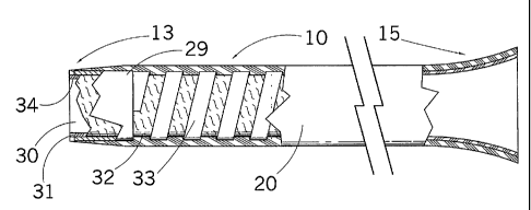
[0023] Fig. 3 depicts an enlarged, partially sectioned view of introducer
sheath
10 of Fig. 1, with dilator 11 and connector valve 14 removed for clarity.
Sheath
10 comprises an inner tube 31, a flat wire coil 33 wound or compression fitted
around inner tube 31, and an outer tube 20. Preferably, outer tube 20 is
mechanically connected to a roughened outer surface 32 of the inner tube 31
through the spacings of the coi133. Outer surface 32 of the inner tube 31 may
be
chemically etched in well-known manner for forming the roughened outer
surface.
5
CA 02523487 2005-10-25
WO 2004/096338 PCT/US2004/012795
[0024] In a preferred embodiment, inner tube 31 comprises a lubricious
material, preferably a fluorocarbon such as polytetrafluoroethylene (PTFE).
Preferably, inner tube 31 has a uniform inside diameter having an inside
diameter
ranging from about 4 to 10 French, more preferably, from 5 to 8 French. The
wall
thickness of inner tube 31 is generally about 0.0015 inch (0.038 mm). These
dimensions are exemplary only, and the inner diameter may be constructed to be
of any size necessary to accomplish the purposes for which the sheath is to be
employed. The lubricious PTFE material presents a slippery inner surface 34 to
allow easy insertion and withdrawal of the dilator 11 as well as other
catheters and
medical apparatus. Inner surface 34 is also smooth and nonporous for
minimizing
the formation of blood clots and other thrombi thereon.
[0025] The uniform inner diameter of inner tube 31 extends the entire length
of
passageway 30 to enable passage of the largest possible diameter catheter or
other
interventional device therethrough. The wall of the inner tube 31 has
sufficient
radial rigidity to prevent the turns of compression-fitted coi133 from
protruding
into inner tube passageway 30.
[0026] Coi133 may be compression fitted or wound around inner tube 31. The
coil includes a plurality of turns, and preferably includes uniform spacings
between the coil turns. Preferably coi133 is stainless steel flat wire,
although
other biologically compatible metals, alloys (including super-elastic alloys),
and
composite materials may also be utilized. In addition, although a flat wire
coil is
preferred, coils of other cross-sectional dimensions, such as round wire, may
also
be utilized. When flat wire stainless steel is used, coil 33 is preferably
formed
from wire that is about 0.003 inch thick by 0.012 inch wide (0.076 mm by 0.30
mm). Preferably, the ends of coil 33 are spaced approximately 5 mm from the
distal end of inner tube 31 and approximately 1.4 cm from the proximal end.
This
spacing permits tapering of the distal tube end and flaring of the proximal
end.
Preferably, the turns of coil 33 are uniformly spaced apart by approximately
0.3
mm. Although it is preferred to use coils having uniformly spaced turns and a
constant pitch, this is not required and coils spaced non-uniform distances,
or at a
varying coil turn pitch may also be used.
6
CA 02523487 2005-10-25
WO 2004/096338 PCT/US2004/012795
[0027] Sheath 10 may be constructed to have any length required to fulfill its
intended purposes. In most cases, the sheath will have a length between about
50
and 125 cm, and most generally, between about 70 and 100 cm. Generally, the
lengths of inner tube 31 and outer tube 20 are the same, and the length of
coi133
will be less than the length of the inner and outer tubes, for the purposes
recited in
the previous paragraph. For an exemplary sheath of 70-90 cm length, the distal
portion, for example the dista160 cm, cm may be covered with a hydrophilic
coating, such as AQ hydrophilic coating.
[0028] Outer tube 20 is formed of any well-known polymer commonly used
for such purpose. Preferably, outer tube 20 comprises a heat formable
polyamide
material, such as nylon. This heat formable material melts upon heating, such
that
portions flow between the turns of the coil and bond to the roughened outer
surface of the inner tube. The pre-melt thickness of the wall of the nylon
tube is
approximately 0.0065 inch (0.17 mm) for exemplary sheaths of 5-8 French.
[0029] In order to construct the sheath 10 according to a preferred embodiment
of the present invention, inner tube 31 is positioned over a stainless steel
mandril
42 as shown in Fig. 4, such that the inner diameter (ID) of the inner tube 31
substantially matches the outer diameter (OD) of the mandril. A flat wire coil
33
having an ID less than the OD of inner tube 31 is compression fitted or wound
around the inner tube. Suitable techniques for compression fitting and winding
coils are well kknown in the art.
[0030] A long, or "major" segment 12, such as a segment having a length of
e.g. 50-100 cm, or even more preferably 55-85 cm, of the outer tube 20 is
longitudinally positioned around inner tube 31 and flat wire coi133.
Preferably,
major segment 12 has a durometer in the range of about 70 to 80 on the Shore D
scale, most preferably about 75. The term "durometer" as used herein is a
common term of art that is normally used to refer to the resistance of
materials
such as rubber or plastics to deformation, typically to deformation by an
indenter
of specific size and shape under a load. The Shore D scale is a common measure
of hardness of plastic materials. A high durometer material is one that is
relatively
inflexible (e.g. harder), whereas a low durometer material is one that is
relatively
7
CA 02523487 2005-10-25
WO 2004/096338 PCT/US2004/012795
flexible (e.g. softer). All durometer readings herein are measured on the
Shore D
scale.
[0031] A plurality of smaller, or "minor", tube segments 16, 17, 18 of
decreasing durometer, to be described in greater detail, extend from major
segment 12 to the distal end of the sheath. Preferably, the length of the
major
segment comprises at least 50% of the length of the outer tube, more
preferably at
least 75%, and even more preferably at least 80-85%.
[0032] Following positioning of major segment 12 as described, segment 16 is
then positioned such that it abuts the distal end of segment 12. In a
preferred
embodiment, segment 16 has a length of about 3 cm, and a durometer in the
range
of about 53-63, preferably 58. Segment 17 is positioned to abut the distal end
of
segment 16. Segment 17 has a length of about 5 cm, and a durometer of about 35
to 45, preferably 40. Finally, in this embodiment, segment 18 is positioned to
abut
the distal end of segment 17. Segment 18 has a length of about 3.2 cm, and a
durometer of about 20 to 30, preferably 25. Preferably, segments 16, 17 and 18
are also longitudinally positioned around the inner tube 31 and flat wire
coi133, in
the same manner as segment 12, although if desired, coi133 may be sized to
terminate prior to one or more of the distal-most segments. If desired, a
radiopaque marker band 29 may be slid under distal segment 18. Marker bands
are well known in the art, and a band formed of any conventional materials may
be
utilized. Preferably, marker band 29 is formed of platinum.
[0033] The reduction in durometer of segments 12, 16, 17, 18 provides a
gradual step-down at the distal end of sheath 10 from a relatively stiff shaft
portion
12 to a relatively soft distal tip portion 18 without abrupt transitions. The
stiff
shaft portion 12 provides the shaft with trackability and non-kinking support
over
a rather long portion of the sheath, and the flexible distal tip enables the
tip to be
as benign as possible. An abrupt transition may otherwise prevent tracking of
the
sheath into remote areas of the vasculature, e.g., the common carotid from the
aorta.
[0034] After outer tube segments 12, 16, 17, 18 have been positioned on inner
tube 31 and flat wire coil 33 as described, heat shrink tube 40 is positioned
such
8
CA 02523487 2008-01-21
that it envelopes inner tube 31, flat wire coi133, and outer tube segments 12,
16,
17, 18, as shown in Fig. 4. Heat shrink tube 40 is somewhat longer than outer
tube
20, and is preferably formed of a fluorinated ethylene propylene heat
slirinkable
material.
[0035] Prior to heating, a space 39 exists between outer tube 20 and inner
tube
31, as well as between the tunis of the coil. When exposed to elevated
temperatures in an oven, heat shrinkable tubing 40 shrinks and causes outer
tube
segments 12, 16, 17, 18 to nlelt. The melted segments flow between the uniform
spacings of the tunis of coil 33 and mechanically connect to roughened outer
surface 32 of inner tube 31, as shown in Fig. 5. The shrink tube is then cut
off,
and the mandril is removed.
[0036] The heat fomlable nylon tube is self-leveling, which provides a uniform
outer diameter surface for outer tube 20. Distal end 13 may be tapered to
provide
a smooth transition to inner dilator 11 or to a catheter. As a consequence of
the
heat treatment, the respective longitudinal ends of the four segments 12, 16,
17, 18
of different durometer nylon tubing bond/melt together to form a single sheath
with three transitions, namely the transition between segments 12 and 16, the
transition between segments 16 and 17, and the transition between segments 17
and 18. The varying durometers of the segments of outer tube 20 transition the
sheath from a rigid shaft at outer tube segment 12 to a soft tip at segnlent
18.
Other details of the construction of sheath 10 are conventional and need not
be
repeated here. Such details are discussed, among others, in U.S. Patent No.
5,380,304.
[0037] Following is a description of an example of the use of sheath 10 in
performing an interventional procedure. In this example, sheath 10 is used for
placing an interventional device, such as a stent, into a patient's carotid
artery. To
initiate the procedure, a needle puncture is made through the patient's slcin
into a
target vessel. A wire guide is then inserted through a bore in the needle into
the
vessel in accordance with the Seldinger technique, and the needle is
withdrawn. A
dilator and sheath combination as shown in Fig. 1 is then threaded over the
wire
guide. The dilator dilates the opening and provides a path to the desired area
of
9
CA 02523487 2005-10-25
WO 2004/096338 PCT/US2004/012795
the vasculature, in this case the aortic arch. In an alternate design, a
dilator may
be inserted followed by introduction of the sheath. In either case, once the
distal
end of the dilator reaches the aortic arch, the dilator is withdrawn from the
sheath.
[0038] A catheter 50 is then inserted over the wire guide into the sheath
through the area vacated by the dilator. Fig. 6 illustrates one example of a
catheter
that may be used to access a smaller branch vessel in the patient's
vasculature.
Catheter 50 has a proximal end 51 and a distal end 53. If desired, distal end
53
may be formed of a radiopaque material. Preferably, catheter 50 comprises a
nylon construction having a stainless steel braid within the nylon to provide
enhanced torque. Distal end 53 of catheter 50 may include a curve or angle of
a
pre-selected configuration, to enable distal end 53 to mimic the vascular
pattern at
the target site to the extent feasible, and thereby facilitate insertion of
the catheter
and wire guide into the selected smaller vessel site. Catheter 50 may be
constructed or formed to have virtually any shape that may be desired for a
particular purpose. Fig. 7 shows catheter 50 inserted into sheath 10. As
shown,
the distal end 53 of catheter 50 extends in the distal direction beyond the
distal end
13 of sheath 10. Conventional marker band 29 may be provided at the distal end
of sheath 10.
[0039] The smaller neurocirculation vessels that may be a target of the
technician comprise a tortuous pathway that branches off from the aorta. The
neurocirculation target vessels include arch vessels like the subclavian
vessels, the
left common carotid and the innominate/brachiocephalic arteries. The curved
distal end 53 of catheter 50 can be manipulated to enter into the desired
area. The
sheath can then be telescoped over the catheter that previously protruded from
the
end of the sheath inside the desired remote vessel, and catheter 50 can be
removed.
An interventional procedure, such as the placement of a stent (with or without
a
balloon), may now be performed. The flexibility of the sheath at the distal
tip
enables it to be benign in, e.g., the common carotid as the beating heart
causes it to
bob up and down.
[0040] A particularly preferred catheter that may be used with the inventive
sheath is a selected one of the family of catheters known as SLIP-CATH
CA 02523487 2005-10-25
WO 2004/096338 PCT/US2004/012795
catheters, manufactured by Cook Incorporated, of Bloomington, IN. SLIP-
CATH catheters are provided in a variety of sizes and distal-end
configurations,
to enable the physician to select an optimally-shaped catheter for a
particular
application. SLIP-CATH catheters are provided in configurations particularly
suitable for cerebral or visceral use. The catheter shown in Fig. 6 includes
merely
one example of a distal tip configuration that may be utilized. Those skilled
in the
art will recognize that many other tip configurations may be utilized for a
particular application. The catheters may be provided in any convenient length
from about 40 to 150 cm. When utilized in combination with a sheath having a
length of from about 70 to 100 cm, the optimal lengths of such catheters are
about
120 to 140 cm, preferably 125 cm.
[0041] In addition to the foregoing, it is preferred that the catheter be
sized
such that its outer diameter is between about 0.0005 and 0.004 inch (0.013 and
0.10 mm), less than the inner diameter of the sheath 10. Thus, for exainple,
if the
inner diameter of the inner tube 31 is about 0.100 inch (2.54 mm), then the
outer
diameter of the catheter is in range of about 0.0995 inch (2.53 mm) to about
0.096
inch (2.44 mm). More preferably, the difference in inner diameter of the
sheath 10
to the catheter is about 0.001 inch (0.025 mm) to about 0.003 inch (0.076 mm).
[0042] The close tolerance between the sheath and the catheter prevents the
catheter from knocking loose any plaque that may be lining the inside of the
vessels traversed by the sheath and the catheter. This is often referred to as
the
"snowplowing" effect. Having a diameter difference is this range is also
advantageous because it provides a smooth transition between the catheter and
the
sheath as the catheter is advanced through the sheath to a vessel within the
vasculature of the patient. If the diameter difference is much greater than
about
0.004 inch (0.10 mm), a ledge-type surface may be created. Upon insertion of
the
catheter or sheath into the vasculature, the presence of such a ledge could
damage
the anatomy of any vessel that is traversed by the component as it, is being
advanced. On the other hand, if the difference is much less than about 0.0005
inch
(0.013 mm), there would be virtually no difference, or perhaps even an
interference fit, between the surfaces. This will hinder the relative axial
11
CA 02523487 2005-10-25
WO 2004/096338 PCT/US2004/012795
movement between the catheter and the sheath, thereby causing difficulty
during
the insertion and/or removal of the catheter from the sheath.
[0043] It is preferred that at least the distal portion of the catheter
include a
hydrophilic coating, such as the AQ hydrophilic coating. A hydrophilic
coating
greatly increases the lubricity of the catheter when compared to non-coated
catheters, and provides for ease of insertion and/or removal of the catheter.
Preferably, the hydrophilic coating will comprise about the distal 60 cm of
the
catheter. In addition, it is preferred to utilize a catheter having a
radiopaque distal
tip portion. This may be formed by loading the polymeric matrix of the
catheter
with a suitable radiopaque material, such as tungsten. Alternatively, a
radiopaque
marker band may be positioned around a distal portion of the catheter in
conventional fashion.
[0044] It is not necessary to use a dilator 11 in all applications. In some
applications, the combination of sheath and catheter 50 can be used to dilate
the
initial opening, and the step of using a separate dilator 1 l may be omitted.
[0045] The durometer ranges recited above are preferred because they provide
a sheath that has the versatility to be used for a wide variety of
applications.
However, those skilled in the art will recognize that other durometer ranges
may
be substituted, and indeed, may be preferred for any specific application. The
scope of the invention includes any sheath having a gradual decrease in
durometer
at the distal end to permit manipulation of the sheath such that it can be
introduced
into small diameter tortuous passages in the vasculature. Preferably, it is
only the
extreme distal end of the sheath, such as the distal 25 to 30 cm, preferably
10 to 15
cm, that is varied in durometer from the main body 12 of the sheath, although
additional variations are possible. Decreasing the durometer over a plurality
of
segments, such as the three segments 16, 17, 18 over the distal 11.2 cm of the
exemplary sheath described, provides a gradual decrease in stiffness, such as
the
described durometer decrease from 75 to 25, in precisely the area of the
sheath
that is often most in need of such variation. However, those skilled in the
art may
prefer a sheath having a more gradual decrease in durometer over a greater, or
12
CA 02523487 2005-10-25
WO 2004/096338 PCT/US2004/012795
lesser, length of the sheath, which variation is also within the scope of the
invention.
[00461 Although the exemplary sheath described above includes four segments
12, 16, 17, 18, a sheath according to the present invention may have more, or
less,
than four segments. For example, the distal end need not be limited to three
relatively short segments, and can include as many segments as desired, as
long as
the segments are aligned to provide a gradual decrease in stiffness (increase
in
flexibility). Given the numerous and varied pathways in the human or animal
vasculature, a sheath can be constructed according to the teachings of the
present
invention to conform specifically to virtually any particular vascular
configuration.
The dimensions provided above are only exemplary, but are believed to provide
a
sheath having sufficient versatility to be useful in a multitude of
applications.
[0047] It is therefore intended that the foregoing detailed description be
regarded as illustrative rather than limiting, and that it be understood that
it is the
following claims, including all equivalents, that are intended to define the
spirit
and scope of this invention.
13