Note: Descriptions are shown in the official language in which they were submitted.
CA 02523942 2005-10-19
EM No. EV fi51899045U5 Attorney Dkt. No. 59507.8001.US00
LAMP INCLUDING A REPLACEABLE ,
LIGHT EMITTING DIODE (LED)
CROSS-REFERENCE TO RELATED APPLICATION
[ppp~] The present application claims priority to Chinese Patent Application
Na. 200520074832.4, filed August 19, 2005, the disclosure of which is
incorporated
by reference herein in its entirety, including drawings.
FIELD 0~ THE INVENTION
[0002] The present invention is directed to a lamp, and more particularly to a
lamp including a light emitting diode (LED) as the lighting source. , '
1p BACKGROUND
[0003] Lamps with an LED light source typically include a tamp cover, the
LED, and a lamp holder. The LED is positioned inside the lamp cover and has
two
legs extending out of a head of the lamp cover through attached lead wires.
The
lamp cover head is then put in a machine for injection, forming a lamp holder
within
which the lamp cover head and the lead wires are tightly enclosed. Producing a
lamp in this manner is relatively difficult and complicated. Additionally, if
the LED or
the Tamp cover breaks, a professional tool is generally required to split open
the
lamp holder and to replace the broken part. The lamp holder must then be
injected
again.
[59507-8001/1A0526B0.048]
CA 02523942 2005-10-19
EM t~o. EV 65~1899045tJS Attorney Dkt. No. 59507.8001.US00,
BRIEF SUMMARY
[oflaal A lamp including an LEA light source is configured such that it is
easy
to assemble and to repair. The lamp includes a lamp cover, an LED, and a lamp
holder. The lamp holder includes a lamp seat, an inner cover, 'and an outer
cover,
all preferably made of an insulating material. An annular groove into which
the head
of the Tamp cover is mounted is provided in the lamp seat.
[UOD5~ ~ Two or more through holes are formed in the lamp seat in a. '.
longitudinal direction to provide openings through which legs on the LED pass.
The
inner cover preferably includes a permanent portion connected to a bottom edge
of
the lamp seat and a movable portion that may be combined with the permanent
portion. Two or more longitudinal channels are formed within an internal space
of
the permanent portion and the movable portion. ~ The longitudinal channels are
positioned adjacent to, and isolated from, each other allowing the LED legs,
which
extend out ~of the lamp seat via through holes therein, to ~ make an
electrical
~! 5 engagement with lead wires projecting upwardly from the bottom end of .
the
longitudinal channels. The inner cover and the embedded lead wires are
inserted
into the outer cover.
[0006 The internal space of the permanent portion includes art insulation
projection that separates the internal space of the permanent portion ~ into
two
.longitudinal channels. Each of the longitudinal channels is in communication
with
one of the respective through holes of the Lamp seat. The internal space of
the
movable portion is recessed with a groove extending longitudinally along the
internal
[595Q7-80011l.r4052B60.0a8] 2-
CA 02523942 2005-10-19
EM No, EV 851899Q45U5 Attorney Dkt. No, bySUi.tsuun.uwv
space of the movable portion for receiving the insulation projection of the
permanent
portion.
[0007 A pair of directive blocks having an angle of inclination is provided at
the upper end of each~of the longitudinal channels of the permanent portion,
with
the directive blocks forming a.space adjacent to the LED into two narrow
slots. A
pair of directive recesses with an oblique angle inclined toward the LED is
provided
in the internal space of the movable portion at a position corresponding to
the
directive blocks of the permanent portion.
[0008] Each of two or more conductive plates, each of which is connected to
an end of one of the lead wires, is held in 'intimate engagement with a
respective
LEA leg extending out of the corresponding through hole at the narrow slot, '
.
[0009] A pair of convex flanges is formed at the lower end of each of the
longitudinal channels of the permanent portion. A convex flange is formed on
each
of the longitudinal channels of the movable portion at a position
correspondingly.
central to the pair of convex flanges of each of the longitudinal channels of
the
permanent portion.
[0070] A corner adjacent to the insulation projection of the permanent portion
includes a positioning pin, and the movable portion includes a positioning
hole at a
corresponding position for engagement with the positioning pin of the
permanent
portion.
(0011] One method of assembling the LED lamp includes positioning each of
the conductive plates into a respective narrow slot of the permanent portion.
The
[59507 8001A.A052860.048] -3..
CA 02523942 2005-10-19
EM No; EV 651899,045US
Attoms~ "~ct. No. 59507.8001.US00
permanent portion is then attached to or otherwise combined with the movable
portion to complete an inner cover. The inner cover is then positioned within
the
outer cover, and the two legs of the LED are inserted through the through
holes of
the lamp seat into the longitudinal channels of the inner cover. ' '.
[0012 The directive blocks at the upper end of the longitudinal channels
guide the LED legs toward a respective narrow slot so that they make contact
with a
respective conductive plate. The lamp cover head is then mounted to the
annular
groove formed in the tap of the lamp seat.
[0D13] The described lamp configuration provides several benefits. For
~ example, if a lamp cover is broken, a repair can be made by pulling the tamp
cover
out of the annular groove and replacing it with a' new (amp cover. ~' if an
LED is
broken, a repair can be made by pulling out the lamp cover and the broken LED
from the lamp seat and replacing the LED with a new LED. If a conductive plate
has
a failure contact with the LED leg, a repair can be made by pulling the inner
cover
95 out of the outer cover and removing the movable portion. Atl of these
repairs are
convenient and may be made without damaging any portion of the LED lamp.
[0014] . ~ Other features and advantages of the invention will appear
hereinafter.
The features of the invention described above can be used separately or
together,
. or in various combinations of one or more of them. The invention resides as
wail in
sub-combinations of the features described. Furthermore, many of the method
steps described herein may be performed in a different order than that which
is
explicitly described.
[59507-8Q09/LA052860_048j -t~.
CA 02523942 2005-10-19
EM NQ. EV 65'1899045US AttarnGy ~kt. No. 59507.8001.US00
BRIEF DESCRIPTION OF THE DRAWINGS , ,
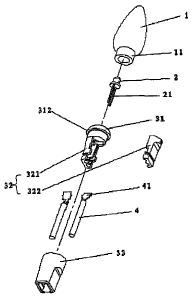
X0015] FIG. 1 is a fragmentary, sectioned, perspective view of an LED lamp
according to one embodiment.
(p0~ ~ F'IG. 2 is an assembled perspective view of the LED lamp illustrated in
FIG.1. ,
(0017 FIG. 3 is a perspective view of a lamp seat and an inner cover of the
LED lamp illustrated in FIG. '!.
DETAILED DE5CRIPTiON OF THE INVENTION
Ipp1 g~ heferring to FIGS. 1 and 2, ari ~ LED lamp includes a lamp cover 1, a
light emitting diode (LED) 2, and a lamp holder 3. The lamp holder 3 includes
a
lamp seat 31, an inner cover 32, and an outer cover 33.
(p0~g] Referring to FIG. 3, an annular groove 311 into which a lamp cover
head 11 may be mounted is provided in the lamp seat 31. Departing from the
central position of the lamp seat 31 in a longitudinal direction is a
positioning flange
312. The interior of the lamp seat 31 includes a cylindrical body having two
or more
openings through holes 314 extending longitudinally through the lamp seat 31.
(OOZO] A plastic-sealed portion of the LED 2 is positioned inside the lamp
cover 1 with the base of the LED seating against the top surface of the
cylindrical
body 313. The LED legs 21 extend out of the lamp cover 1 into and through
respective through holes 314.
[59507-800~/IJ~052860.048] -5-
CA 02523942 2005-10-19
-.- .-., ",."" ~-mu r.uiiiucu rw cu
EM No. EV 6518~99045US ~ Attom~y Jkt No. 59507.8001.US00
[0029) The inner cover 32 includes a permanent portion 321. connected to the
bottom edge of the lamp seat 31, and a movable portion 322 for attachment to
or
combination with the permanent portion 321. The internal space of the
permanent
portion 321 includes an insulation projection 3211 that separates the interior
of the
permanent portion 321 into two longitudinal channels 323. Each of the two
longitudinal channels 323 of the permanent portion 321 is in communication
with a
respective opening or through hole 314 in the lamp seat 31. The internal space
of
the movable portion 322 is recessed with a groove 3221 for receiving the
insulation
projection 3211 of the permanent portion 321.
[0022) A directive block 3212 having an angle of inclination is provided at
the
upper end of each of the longitudinal channels 323 of the permanent' portion
321 for
shaping the space adjacent to the LED 2 into a narrow slot 3213. Directive
recesses 3222, each having an oblique angle inclined toward the LED 2, are
provided in' the internal space of the movable portion 322 at positions
corresponding
to the directive blocks 3212 of the permanent portion 321. A positioning pin
3214. is
fomned adjacent to the insulation projection 3211 and is adapted for fitting
into a
positioning hole 3223 in the movable portion 322.
[0023) Two or more conductive plates 41 are connected to the ends of tvuo or
more corresponding lead wires 4. Each of the conductive plates 41 is. held in
intimate engagement with a respective LED leg 21 extending through an opening
314 into a narrow slot 3213 in the permanent portion 321. .
(59507-8001/LI4052860.048] -6-
CA 02523942 2005-10-19
EM No. w 859899045US Attarn~y ~Ki. no. ab~~~.~~,...".,..,.
(0024] Two convex flanges 325 are formed at the lower end of each of the . ,
longitudinal channels 323 of the permanent portion 321. Convex flanges 3224
are
formed in the internal space of the movable portion 322, with each convex
flange
3224 corresponding to~ ~a central portion located between a pair of the convex
flanges 325 in one of the longitudinal channels 323,. When the permanent
portion
321 and the movable portion 322 ace attached to or otherwise combined with
each
ether, each pair of convex flanges-325 associated with a~ convex flange 3224
tightly
holds a lead wire 4 within a longitudinal channel 323 to eliminate stress
forces
between the lead wino 4 and the conductive plates 41.' Securing the lead wires
4 in
the longitudinal channels 323 in this manner provides a secure' engagement
between the conductive plates 41 of the lead wires 4 and the LED legs 21.
[0025] A groove 324 is formed in the outer wall surface of the inner cover 32,
and a convex fitange is formed at the same position of the inner wall surface
of the
outer cover 33 for engagement with the groove 324. Combining the groove 324
with
the convex flange enables the outer cover 33 to firmly enclose the inner cover
32
with its top edge bearing against the positioning flange 312 of the Lamp seat
31.
[0026 One method of assembling the LED lamp includes positioning the
conductive plates 41 of the lead wires 4 into the narrow slots 3213, -and
fitting the
positioning pin 3214 into the positioning hole 3223 to form the inner cover 32
(which
includes the permanent portion 321 and the movable portion 322). The inner
cover
32 is then inserted into the outer cover 33 to complete the assembly of the
lamp
holder 3. Next, the two legs 21 of the LED 2 are inserted simultaneously into
[59507-80011LA052860.048j -7-
CA 02523942 2005-10-19
EM No, EV 651899045US Attorney ~kt. No. 59507.8DD1.USD0
respective through holes 314 of the lamp seat 31 until the plastic-sealed
portions of
the LED 2 seat stably against the top surface of the lamp seat 31. The LED
legs 2
exit the lamp seat 31 via through holes 314 for engagement with the
corresponding
conductive plates 41 'at the narrow slots 3213 of the permanent portion 32.
The
lamp cover head 11 is then mounted in the annular groove 311 of the lamp seat
31.
[0027a Jf the LED lamp cover is broken, a repair can be made by.pulling the
lamp cover out of the ring-shaped groove and replacing it with a new lamp
cover. If
an LED is broken or otherwise inoperable, a repair can be made by pulling the
lamp
.cover out of the ring-shaped groove, and pulling the bad LED from the lamp
seat
and replacing it with a new LED. If a conductive plate has a failure contact
with the
LED leg, a repair can be made by pulling the inner cover out of the outer
cover, and
removing the rnovable part. All of this repair work can be conveniently
performed
without damaging any section of the LED tamp.
~0028~ Thus, while, several embodiments have been shown and described,
various changes and substitutions may of course be made, without departing
from
the spirit and scope of the invention. Many of the method steps described
herein,
for example, may be pertormed in a different order than that which is
specifically
described. The invention, therefore, should not be limited, except by the
following
claims and their equivalents.
159507-8001 /LA052860.048] -$-