Note: Descriptions are shown in the official language in which they were submitted.
CA 02524477 2005-11-02
WO 2004/099024 PCT/EP2004/004466
VALVE CLOSURE
1
The present invention relates to a closure used to
seal a container having a valve. In particular, the
closure is designed to prevent leakage from the valve
during transport or storage of the container.
Many liquid food products (e.g. honey and sauces
such as tomato sauce) are now packaged in containers
incorporating a valve, which is used to control
dispensing of the product. Also, liquid toiletries, such
as shower gel are packaged in such containers, because
the valve allows the container to be stored in an
inverted position without substantial loss of product,
whilst allowing easy dispensing of the product upon
activation of the valve. In many cases, a self-closing
valve is preferred. A self-closing valve opens in
response to increased product pressure in the container,
achieved for example by a user squeezing the container.
When the product pressure is relieved, the valve
automatically assumes a closed configuration in which the
valve opening is substantially sealed. However, such
valves are known to leak a little over time and may be
activated accidentally during mishandling or pressure /
temperature variation during transport.
To overcome these problems, it is known to provide
an overcap for the valve, which prevents the valve from
opening or leaking, during prolonged storage or
transport. Many different types of overcap arrangement
are described in the prior art. Conventional overcap
CA 02524477 2010-10-06
30856-4
2
designs are concerned with preventing leakage from the
dispensing orifice in the valve.
In contrast, the present invention is based upon the
acceptance that all valves will leak to some degree, but
the level of leakage may be controlled to acceptable
levels by reducing the volume of the cavity into which
leakage can.occur.
Accordingly, an aspect of the present invention provides a
closure for a container, the closure having g-a body, a
valve comprising a 'valve head, said valve head having an
=opening through which the contents of the container may
be dispensed, and a lid, moveable between open and closed
positions relative to the body, and shaped to block the
opening.. in the valve, when the lid is in its closed
position, wherein the lid has an annular projection,
located immediately adjacent the periphery of the valve
head, so that in use with the lid in its closed position,
the projection forms-an annular peripheral seal. around
the valve opening, and the shape of the lid within the
periphery of the projection substantially conforms to the
shape-of the=body and/or valve head within the peripheral
seal, such that when the lid is in its closed position it
contacts the body and/or valve head over substantially
the whole of=the area thereof within the peripheral seal
to minimise the volume therebetween.
Therefore, the closure according to an aspect of the invention
has an open position, in which the contents of the-
container may be dispensed and a closed-position (for*
CA 02524477 2010-10-06
30856-4
3
transport or storage), where the closure lid defines a-
peripheral, fluid tight seal around the valve opening.
The shape of the lid within the boundary of this
peripheral seal is closely matched to the shape of the
valve and surrounding closure parts lying within the
periphery of the seal. in this way, the volume into which
the valve may leak is minimised and. any leakage that
occurs is limited to an acceptable level in the eyes of
the user.
In an embodiment of the invention, the
closure comprises a body, which carries the valve and is
designed to engage the container neck, either removeably
(using a screw thread arrangement, for example) or
permanently (using a snap-fit arrangement, for example)
The closure also has.a lid, which is capable of moving
relative to the body between open and closed positions.
When the lid is. in its open position, the contents of the
container may be dispensed through the opening in the
valve. However, when the lid is in its closed position,
it blocks the valve opening, preventing substantial
leakage from the valve.
Unlike the sealing systems described in the prior
art, the lid is not intended to prevent leakage entirely,
instead the aim-of the invention is to minimise the
volume into which leakage may occur, thus controlling the
leakage to acceptable levels. If the volume is
sufficiently small, then the leakage will form a thin
CA 02524477 2010-10-06
30856-4
3a
film and-surface tension prevents, a drip forming. Thus,
the surface appears clean.
Accordingly, in some embodiments of 'the present invention, the lid is
provided with a projection, which is adapted to form a
'5 fluid-tight, peripheral seal around the valve opening.
The fluid-tight seal may be formed by the lid projection
CA 02524477 2010-10-06
30856-4
4
applying pressure directly to the valve around the valve
opening. However, in some cases this is not desirable,
particularly where the valve-is made from a material
which is prone to creep when subjected to an applied
load. Such creep may reduce the effectiveness of the
peripheral seal over time or may affect the normal
dispensing operation of the valve.
An advantage of some embodiments of the present
invention is that the peripheral seal may be provided by
interaction between the two most suitable surfaces.
Therefore, if the valve is prone to creep, the projection
may be arranged to cooperate with the closure body, rather
than the valve and thereby create an effective fluid tight
seal. Advantageously, the lid projection and the closure
body of some embodiments are designed to form a bore seal
therebetween, when the lid is in its closed position.
In order to minimise the volume into which leakage
may occur, the shape of the lid, within the periphery of
the projection must closely match the shape of the valve
and/or body of the closure within the peripheral seal,
when the lid is in its closed position. In addition, if
the valve is prone to creep and the peripheral seal is
therefore formed between the lid projection and the
closure body, the shape of the valve protruding from the
closure body must be relatively simple, to enable close
matching of the portion of the lid within the projection
and the portion of the closure body and valve within the
peripheral seal.
CA 02524477 2010-10-06
30856-4
4a
According to another aspect of the invention, there is provided a
closure for a container, the closure having a body, a valve comprising a valve
head, and a connecting wall, said valve head having an opening through which
the contents of the container may be dispensed, and a lid, moveable between
open and closed positions relative to the body, and shaped to block the
opening in
the valve, when the lid is in its closed position, wherein the lid has an
annular
projection, located adjacent the periphery of the valve head, and the shape of
the
lid within the periphery of the projection substantially conforms to the shape
of the
valve head, such that when the lid is in its closed position it contacts the
valve
head over substantially the whole of the area thereof within the periphery of
the
projection to minimise the volume therebetween, wherein the annular projection
is
configured either to press against the surface of the valve head within the
periphery thereof, or against the body adjacent the connecting wall radially
outside
the valve head, so that in use with the lid in its closed position, the
projection
forms an annular peripheral seal around the valve opening and minimizes the
volume between the valve head and the lid within the annular projection.
CA 02524477 2005-11-02
WO 2004/099024 PCT/EP2004/004466
The present invention will now be described, by way
of example only, with reference to the accompanying
drawings, in which
FIGURE 1 shows a valve sealing arrangement according to a
5 first embodiment of the invention, comprising a
conventional self-closing valve not prone to excessive
creep and a lid, shown in its closed position.
FIGURE 2 shows a valve sealing arrangement according to a
second embodiment of the invention, comprising a
conventional self-closing valve not prone to excessive
creep and a lid, shown in its closed position
FIGURE 3 shows a closure according to a third embodiment
of the invention, having a self-closing valve prone to
creep and lid, shown in its closed position.
Wherever possible, like components have been
referenced using the same reference numerals.
According to figures 1 and 2, a valve sealing
arrangement comprises a conventional self-closing valve 1
held in a body 2 by a clip 3 and a lid 5, moveable
relative to the body 2 between open and closed positions.
The body 2 may either form part of a container or a
closure. In figures 1 and 2, the clip is shown attached
to the internal surface of the body 2, although it will
be appreciated that the relative positions of the body 2
and the clip 3 may be reversed and the clip 3 may be
attached to the external surface of the body 2. The clip
CA 02524477 2005-11-02
WO 2004/099024 PCT/EP2004/004466
6
3 clamps the valve 1 in the body 2, by means of a snap
fit connection 23 between the body 2 and the clip 3.
The valve 1 comprises a securement flange 11,
connected to a valve head 15 by a connecting wall 12. The
valve head takes the form of an inwardly concave dish,
with an opening 17 provided in the centre thereof. In
figures 1 and 2, the connecting wall 12 of the valve 1
takes the form of a V-shaped elbow, although many
different connecting wall configurations are known from
the prior art. For example, the connecting wall may have
a loose folded configuration, which functions like a
rolling diaphragm upon opening of the valve or a simple
linear configuration, which simply stretches slightly, as
the valve opens.
Referring now to figure 1, the lid 5 is provided
with an annular projection 51, which encircles the valve
opening 17. The annular projection 51 is designed to
apply an axial sealing force F to the valve head 15,
which is braced by the opposing support 31 provided by
the clip 3. The interaction between the annular
projection 51, the valve head 15 and the support 31,
produces the sealing force F, which creates a fluid-tight
seal A around the periphery of the valve opening 17. The
shape of the lid within the periphery of the projection
51, closely matches the shape of the valve head 15 within
the periphery of the annular seal A. Thus, the volume
defined between the lid 5 and the valve head 15 within
the periphery of the annular seal A is reduced to a
CA 02524477 2005-11-02
WO 2004/099024 PCT/EP2004/004466
7
minimum, thereby minimising the volume of leakage that
can occur from the valve opening 17.
Figure 2 shows an alternative valve sealing
arrangement, in which no force is applied to the valve
head 15. This may be an important consideration where the
design of the valve head is critical and therefore the
application of forces to the valve head for a prolonged
period is undesirable. In this arrangement, the body 2 is
designed to apply a radial sealing force F to the
connecting wall 12. The dimensions of the aperture in the
body 2, through which the valve head 15 protrudes, are
chosen to provide the necessary radial sealing force F to
form a fluid-tight annular seal A. In this arrangement,
the lid 5 has an annular flange 55, which is arranged to
form a bore seal with an annular collar 25 provided in
the body 2. The tip 56 of the annular flange 55 may also
be designed to form a face seal within the recess 21
formed in the body 2 adjacent to the collar 25.
The fluid-tight seal A extends around the periphery
of the valve head 15 and thereby encompasses the valve
opening 17. The shape of the lid 5 within the periphery
of the annular flange 55, closely matches the shape of
the valve 1 within the periphery of the annular seal A.
Thus, the volume defined between the lid 5, the valve
head 15 and valve connecting wall 12 within the periphery
of the annular seal A is reduced to a minimum.-Thereby
minimising the volume of leakage that can occur from the
valve opening 17.
CA 02524477 2005-11-02
WO 2004/099024 PCT/EP2004/004466
8
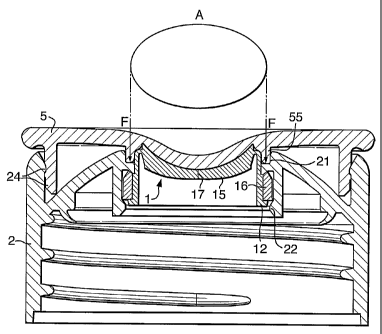
Referring now to figure 3, which shows a closure
according to the present invention having a valve, which
is made from a material that is prone to creep or
distortion when subjected to an applied load for
prolonged periods, for example TPE. The advantage of TPE
is that it can be used to produce valves at low cost and
is suitable for sequential moulding with other materials
such as rigid polypropylene (PP).
In the embodiment shown in figure 3, a TPE valve 1
is sequentially moulded to a rigid polypropylene ring 16.
The polypropylene ring 16 is clipped into a closure body
2 and is held in place by a bead 22. The valve has a
dish-shaped, inwardly concave valve head 15, which is
connected to the polypropylene ring 16 by a connecting
wall 12. The closure also includes a removable lid 5,
which is closed on the body 2 and secured in position by
means of a snap fit arrangement 24. The lid 5 does not
apply any forces to the valve 1, because this could cause
distortion. Instead, the lid 5 has an annular flange 55,
which is designed to co-operate with the closure body 2
to form a peripheral fluid-tight seal around the valve
opening 17. The annular flange 55 is arranged to form a
bore seal within an annular channel 21 provided in the
body 2. The tip of the annular flange 55 may also be
designed to form a face seal within the annular channel
21 as previously described with reference to the
embodiment shown in figure 2. Thus, the annular flange
55, may be adapted to form a fluid-tight peripheral seal
CA 02524477 2005-11-02
WO 2004/099024 PCT/EP2004/004466
9
A in the form of a bore seal, a face seal or a
combination of the two.
The fluid-tight seal A extends around the periphery
of the valve head 15 and thereby encompasses the valve
opening 17. The shape of the lid 5 within the periphery
of the annular flange 55, closely matches the shape of
the valve 1 within the periphery of the annular seal A.
Thus, the volume defined between the lid 5, the valve
head 15 and valve connecting wall 12 within the periphery
of the annular seal A is reduced to a minimum. Thereby
minimising the volume of leakage that can occur from the
valve opening 17.
The embodiments described above are provided as an
illustration of the invention only and many other
configurations of valve and arrangements of the closure
will be apparent to the person skilled in the art. The
invention is ideally suited to liquid seals, where the
reduction in leakage volume allows positive surface
tension effects to occur. However, the invention is also
suitable for gas seals (for example for processed and /
or aseptically filled foods) where a hermetic quality
seal is required. The valve closure according to the
invention can meet this requirement and thus a separate
foil seal is not required (e.g. closures for sauce
bottles often need a barrier foil under the closure).