Note: Descriptions are shown in the official language in which they were submitted.
CA 02524834 2005-10-31
ROTARY AGITATOR FOR PROVIDING OSCILLATING
NAP CLEANING ACTION
This application claims the benefit of U.S. Provisional Patent
Application serial no. 60J623,416 filed on 29 October 2004.
Technical Field
The present invention relates generally to the floor care equipment
field and, more particularly, to a rotary agitator with an agitator element
providing oscillating nap cleaning action, a floor care appliance equipped
with such a rotary agitator and to a method of cleaning a carpet or rug.
Background of the Invention
A vacuum cleaner is an electrically powered, mechanical appliance
utilized for the dry removal of dust and loose dirt from carpets, rugs,
fabrics and other surfaces. Vacuum cleaners have been widely utilized for
years in domestic and industrial cleaning applications.
In operation, a pressure drop is utilized to force air entrained with
loose dirt and dust into the nozzle of the vacuum cleaner. The dust and dirt
laden air is then drawn through a bag or dirt cup which traps and retains the
CA 02524834 2005-10-31
2
dirt. The air is then exhausted by electric fan through an additional filter
to
remove relatively fine particles. It is this fan that provides the air
pressure
drop or vacuum that provides the cleaning action.
The present invention relates to a rotary agitator for a floor cleaning
apparatus such an upright vacuum cleaner, canister vacuum cleaner,
handheld vacuum cleaner, an extractor or the like. The rotary agitator is
equipped with one or more agitation elements adapted to sweep the nap of
an underlying rug or carpet in an oscillating, side-to-side manner. This
cleaning action functions to more efficiently and effectively loosen and
expose dirt and debris embedded down in the nap of a rug or carpet to the
suction airstream so that it may be quickly drawn into the vacuum cleaner.
This results in better cleaning.
Summar~of the Invention
In accordance with the purposes of the present invention as
described herein, a rotary agitator is particularly adapted to provide high
efficiency, deep cleaning of dirt and debris from the nap of an underlying
rug or carpet. The rotary agitator includes a body that has an axis of
rotation and a zero degree pitch plane perpendicular to that axis of rotation.
Further the rotary agitator has at least one agitation element having a first
portion provided at a positive pitch angle relative to the zero degree pitch
plane and a second portion provided at a negative pitch angle relative to the
zero degree pitch plane.
CA 02524834 2005-10-31
3
The agitation element may comprise any number of different
structures including but not limited to a series of bristle tufts, a wiper, a
brush and a beater bar. The agitation element may be substantially
continuous or even comprise an oscillating ring.
Stated another way, the rotary agitator of the present invention
comprises a body including an axis of rotation and a zero degree pitch
plane perpendicular to that axis of rotation. In addition, the rotary agitator
includes at least one endless agitation element carried on the body and
straddling the zero degree pitch plane. More specifically, the endless
agitation element includes (a) a first portion extending in a first arc from
the zero degree pitch plane to a first point a first distance in a first
direction
from that pitch plane and then back to the pitch plane and (b) a second
portion extending in a second arc from the pitch plane to a second point a
second distance in a second direction from the pitch plane and then back to
the pitch plane. That first distance A may be between about 0.5 and 3.0
cm. Further, the second distance may be substantially equal to the first
distance.
In accordance with another aspect of the present invention a method
is provided for removing dirt and debris from the nap of a rug or carpet.
The method comprises providing a rotary agitator with an oscillating
agitation element that functions to push the nap in a side-to-side motion
during rotation of the rotary agitator.
In accordance with yet another aspect of the present invention a
floor cleaning apparatus is provided. That floor cleaning apparatus
CA 02524834 2005-10-31
4
comprises a housing, a suction generator carried on the housing, a dirt
collection vessel carried on the housing and the rotary agitator of the
present invention.
In the following description there is shown and described several
possible embodiments of the invention, simply by way of illustration of
some of the modes best suited to carry out the invention. As it will be
realized, the invention is capable of other different embodiments, and its
several details are capable of modification in various, obvious aspects all
without departing from the invention. Accordingly, the drawings and
descriptions will be regarded as illustrative in nature and not as
restrictive.
Brief Description of the Drawings
The accompanying drawings incorporated in and forming a part of
the specification, illustrate several aspects of the present invention, and
together with the description serve to explain certain principles of the
invention. In the drawings:
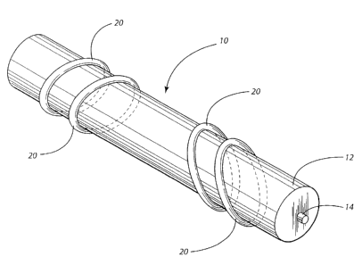
Figure 1 is a perspective view of the rotary agitator of the present
invention;
Figure 2a is a schematical elevational view illustrating the geometry
of the agitation element carried on the agitator;
Figure 2b is a detailed perspective, schematical view illustrating the
arcs formed by the agitation element;
Figures 3a and 3b are schematical side elevational views illustrating
how the rotary agitator functions to push or brush the nap of an underlying
CA 02524834 2005-10-31
carpet from side-to-side;
Figure 4 illustrates a vacuum cleaner equipped with the agitator of
Figure 1; and
Figures Sa-Sf illustrate several additional embodiments of the
5 rotary agitator of the present invention.
Detailed Description of the Invention
Reference is now made to Figure 1 illustrating the rotary agitator 10
of the present invention. The rotary agitator 10 includes a body 12. In the
illustrated embodiment the body 12 is cylindrical in shape but other shapes
could be provided. The body 12 may be molded from plastic, machined or
cast from metal such as aluminum or constructed from any other
appropriate material. In the illustrated embodiment the body 12 carries an
axle or stub shafts 14 that extend from each end. As best illustrated in
Figure 2 the body 12 also includes an axis of rotation 16 defined by the
axle or stub shafts 14 and a zero degree pitch plane 18 perpendicular to the
axis of rotation 16.
As also illustrated in Figures 1, 2a and 2b, at least one agitation
element 20 is carried on the body 12 of the rotary agitator 10. The
agitation element 20 may assume any appropriate form including but not
limited to a wiper, a brush, a beater bar and a series of bristle tufts. Each
element 20 may be molded as an integral part of or affixed to the agitator
body 12. In the illustrated embodiment, each agitation element 20 is
substantially continuous so as to be effectively endless. Further, each
CA 02524834 2005-10-31
6
agitation element 20 straddles the zero degree pitch plane 18 so as to
effectively form an oscillating ring as the agitator 10 is rotated (note
particularly Figure 2a) with respect to a fixed point on the surface being
cleaned.
More specifically, each agitation element 20 has a first portion 22
provided at a positive pitch angle A, relative to the zero degree pitch plane
18 and a second portion 24 provided at a negative pitch angle AZ relative to
the pitch plane 18.
Described another way each endless agitation element 20 includes a
first arc 26 extending from the pitch plane 18 to a first point 28 a first
distance in a first direction from the pitch plane 18 and then back to the
pitch plane (see Figure 2b). Additionally, the agitation element 20 includes
a second arc 30 extending from the pitch plane 18 to a second point 32 a
second distance in a second direction from the pitch plane 18 and then back
to the pitch plane. The distance between the first point 28 and the pitch
plane 18 may be between about 0.5 and 3.0 cm. The second distance
between the second point 32 and pitch plane 18 may be substantially equal
to that first distance.
As the rotary agitator 10 rotates about the axis of rotation 16, the
agitation elements 20 first push, brush or comb the nap of an underlying
carpet being cleaned in a first direction toward the ends of the agitator
(note action arrows D, in Figure 3a). Pushing, brushing or combing nap in
this direction occurs as the rotary agitator rotates through the first 180
degrees of its rotation.
CA 02524834 2005-10-31
7
As the rotary agitator 10 rotates through its second 180 degrees of
rotation, the nap of the underlying rug or carpet being cleaned is pushed,
brushed or combed in a second opposite direction toward the middle of the
agitator (note action arrows DZ in Figures 3b) by the agitation elements 20.
As the rotary agitator 10 continues to rotate, the nap is brushed back
and forth from side to side so as to insure that dirt and debris on two sides
of the nap is not only loosened but also fully exposed to the suction
airstream of the floor cleaning device to which the rotary agitator is
attached. This differs from agitators of the prior art that incorporate
agitation elements that only brush the nap to one side thereby laying the
nap over to that one side and holding it there so as to trap dirt and debris
underneath the nap. By avoiding this problem, the present invention
insures more efficient and effective deep cleaning of the underlying rug or
carpet.
A vacuum cleaner 50 incorporating a rotary agitator 10 of the
present invention is illustrated in Figure 4. The vacuum cleaner 50
includes a housing, generally designated by reference numeral 52,
including a nozzle assembly 54 and a handle assembly 56. As is known in
the art, the handle assembly 56 is pivotally connected to the nozzle
assembly 54 to aid the operator in manipulating the vacuum cleaner 50
back and forth across the floor. Wheels (not shown) carried on the
housing 52 allow the vacuum cleaner 50 to be moved smoothly across the
floor. As illustrated, the nozzle assembly 54 is equipped with a nozzle
inlet 58. The rotary agitator 10 is mounted for rotation on the nozzle
CA 02524834 2005-10-31
g
assembly S4 across the nozzle inlet S8 by means of an end cap and bearing
assembly S9 provided on each end of the agitator 10 in a manner well
known in the art (see Figures 3a and 3b).
The housing 52 houses a suction generator 62 (i.e. a fan and motor
S assembly) and a dirt collector 64 having an internal dirt collection
chamber. In one possible embodiment, the dirt collector 64 comprises a
filter bag. In another possible embodiment the dirt collector 64 comprises
a dirt cup. That dirt cup may be substantially cylindrical in shape and
include a tangentially directed air inlet and an axially directed air outlet.
Such a structural arrangement produces cyclonic airflow which helps
separate dirt and debris from the airstream and increase cleaning
efficiency.
The handle assembly 56 also includes a control stalk 68 and an
actuator switch 66 for turning the vacuum cleaner SO on and off and
1 S thereby driving the rotary agitator 10 and the suction generator 62.
In operation, the rotary agitator 10 efficiently brushes dirt and
debris from the nap of an underlying carpet. By brushing the nap from
side-to-side, dirt and debris on both sides of the nap is exposed to the
vacuum airstream so that it may be more efficiently drawn into the vacuum
cleaner (note agitation elements 20 aligned with suction inlets 67 in the
nozzle assembly 54 as illustrated in Figure 3a). This represents a
significant improvement over prior art agitators that tend to brush nap to
one side laying that nap over dirt and debris on that side and effectively
shielding that dirt and debris from the vacuum airstream. Loosened dirt
CA 02524834 2005-10-31
9
and debris is drawn into the dirt collector 64 through the suction inlets 67
by means of the suction generator 62. Dirt and debris is trapped in the dirt
collector 64 and the now clean air is directed over the motor of the suction
generator 62 before being exhausted into the environment through the
exhaust vent 70.
The foregoing description of a preferred embodiment of the
invention has been presented for purposes of illustration and description. It
is not intended to be exhaustive or to limit the invention to the precise form
disclosed. Obvious modifications or variations are possible in light of the
above teachings. For example, while the illustrated embodiment in Figure
4 is an upright vacuum cleaner 50, the present invention also relates to and
includes canister and handheld vacuum cleaners as well as extractors.
Further, while the illustrated embodiment is a "clean air" system with a
suction generator 62 downstream from the dirt collector 64, the present
invention also includes "dirty air" systems where the suction generator is
located upstream of the dirt collector. Further, while the illustrated
vacuum cleaner 50 includes one rotary agitator 10, it could include two or
more rotary agitators if desired.
It should also be appreciated that the agitator 10 may also take the
form of other embodiments as illustrated in Figures Sa-Se. In Figure Sa,
the agitator 10 includes a series of separate and parallel cleaning rings 80
for agitation elements. In Figure Sb, the agitation element is a single,
coiled element 82 that extends around and along the length of the agitator
10. All portions of the element 82 angle in the same direction with respect
CA 02524834 2005-10-31
to plane 18 but the amount of the included angle varies to produce an
oscillation as the agitator 10 rotates. In Figure Sc, the agitator 10 includes
agitation elements comprising a series of separate and alternating cleaning
rings 84.
5 In Figure Sd, the agitator 10 includes two sets of separate cleaning
rings 86, 88. The first set of rings 86 are on a first side of the centerline
CL of the agitator 10 and are angled in a first direction. The second set of
rings 88 are on a second side of the centerline CL and are angled in a
second direction. The number of rings in each set match and the angles of
10 inclination are equivalent so that all forces are balanced and the nozzle
is
steady as the agitator 10 rotates. In Figure Se two separate coils 90, 92 are
provided with one on each side of the centerline CL of the agitator 10. The
coils 90, 92 are mirror images of each other. In Figure Sf, an agitator 10 is
illustrated incorporating multiple oscillating elements 94 having varying
angles with respect to the pitch plane 18 mirrored about the center line CL.
The embodiments were chosen and described to provide the best
illustration of the principles of the invention and its practical application
to
thereby enable one of ordinary skill in the art to utilize the invention in
various embodiments and with various modifications as are suited to the
particular use contemplated. All such modifications and variations are
within the scope of the invention as determined by the appended claims
when interpreted in accordance with the breadth to which they are fairly,
legally and equitably entitled. The drawings and preferred embodiments do
not and are not intended to limit the ordinary meaning of the claims and
their fair and broad interpretation in any way.