Note: Descriptions are shown in the official language in which they were submitted.
CA 02524934 2005-11-07
WO 03/094811 PCT/US03/14574
METHOD FOR TREATING WOUND,
DRESSING FOR USE THEREWITH
AND APPARATUS AND SYSTEM FOR FABRICATING DRESSING
[001] The present invention generally relates to wound treatment and
systems and methods of preparing a wound dressing. More particularly, it
relates to a
wound treatment including a dressing adapted to match the wound site.
[002] Currently, the common method of wound treatment is to cover the
wound with a wound dressing. The wound dressing is manufactured as a precut
sheet
of multi-layer material of various shapes and sizes. The wound dressing is
applied to
cover the wound and a portion of the surrounding healthy skin. Sometimes the
wound
dressing is cut to reduce the size and to better fit the wound size and shape.
This
reduces the amount of healthy skin covered by the dressing.
[003] A typical wound commonly has two or more regions or areas,
including necrotic, sloughy, bacteria colonized, granulating, epitheliazing,
bleeding,
exudating, and drying. An exemplary wound 10 has a granulating area 12 having
heavy exudates and an epitheliazing area 14 having low exudates, which are
surrounded by healthy skin tissue 16 (see FIG. 1). The wound 10 and its areas
12, 14
are usually of irregular shapes. The areas 12 and 14 of the wound 10 typically
differ
from each other by healing stage, depth, contamination, infection, and tissue
stress
due to patient body movement. Consequently, covering the whole wound area and
surrounding healthy skin with the same dressing type may create adverse
conditions
for certain areas of the wound or the surrounding skin, which may increase the
healing time or even cause adverse effects such as secondary dermatitis.
[004] Accordingly, there is a need in the art for a method for wound care that
provides the optimal conditions for wound healing by matching the size, shape,
and
material properties of a wound dressing to the wound area. There is a further
need for
a system to produce such a wound dressing.
[005] The accompanying drawings, which are somewhat schematic in many
instances and are incorporated in and form a part of this specification,
illustrate
exemplary embodiments of the invention and, together with the description,
serve to
explain the principles of the invention.
CA 02524934 2005-11-07
WO 03/094811 PCT/US03/14574
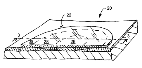
[006] FIG. 1 is an isometric view of a typical wound.
[007] FIG. 2 is an isometric view of a wound covered with a wound dressing
according to one embodiment of the present invention.
[008] FIG. 3 is a sectional view of the wound dressing taken along the line 3-
3 in FIG. 2.
[009] FIG. 4 is a flow chart showing a method of treating a wound using a
wound dressing according to one embodiment of the present invention.
[010] FIG. 5 is a schematic view of a wound dressing fabrication system
according to one embodiment of the present invention.
[011] FIGS. 6A and 6B are flow charts illustrating the steps performed by
the processor of the system shown in FIG. 5, according to various embodiments
of the
invention.
[012] FIG. 7 is schematic view of a portion of a wound dressing fabrication
device.
[013] FIG. 8 is an isometric view of a device for fabricating a wound
dressing according to one embodiment of the present invention.
[014] FIG. 9 is a partial isometric view the device of FIG. 8.
[015] A wound 20 is covered by an adapted or customized wound dressing
22 (see FIG. 2). The wound dressing 22 may include two or more regions or
layers.
Each region or layer is customized to match a size and shape of the wound (see
FIGS.
2 and 3). It is further customized to address one or more wound healing needs.
In
one embodiment, the wound dressing 22 includes a first region 26, second
region 28,
and a backing film 30 (see FIG. 3). The first region 26 of the wound dressing
22 is
located generally near a center of the wound dressing 22 and is sized and
shaped to
generally match or engage the first (e.g., granulating) area 12 of the wound
20. The
second region 28 of the wound dressing 22 surrounds the first region 26 and is
sized
and shaped to generally match or engage the second (e.g., epitheliazing) area
14 of the
wound 20.
[016] The first and second regions 26 and 28 are typically contiguous to
match the contiguous first and second areas 12, 14 of the wound 20. The
backing film
30 is positioned on top of the first region 26 and the second region 28 and
extends
radially outward from the second region 28. The exposed surface of the backing
film
30 generally corresponds to the healthy skin surrounding the wound 20. In
another
-2-
CA 02524934 2011-02-11
71651-99
embodiment, the wound dressing 22 includes only one of the first region 26,
and
the second region 28, in combination with the backing film 30. In one
embodiment, the first region 26 in the second region 28 include multiple
layers of
material having differing material properties.
[017] The present invention, according to one embodiment, is a method 40
for treating a wound on a patient using the adapted or customized wound
dressing 22 (see FIG. 4). In general terms, the method includes evaluating a
set
of wound characteristics (block 42), defining the properties of a wound
dressing
based on the wound characteristics (block 44), fabricating the wound dressing
(block 46), and applying the wound dressing to the wound (block 48).
According to one aspect of the present invention, there is provided a
system for fabricating a wound dressing customized for a wound, the system
comprising: one or more actuators within the system, the one or more actuators
configured to cause relative motions between materials for fabricating the
customized wound dressing; and a controller configured to receive wound
dressing specification defining characteristics of the customized wound
dressing,
the characteristics comprising at least a shape of the customized wound
dressing,
the controller connected to the one or more actuators to control the one or
more
actuators based on the wound dressing specification to shape and prepare the
customized wound dressing as defined by the wound dressing specification.
According to another aspect of the present invention, there is
provided a method of fabricating a wound dressing customized for a wound at an
automated system, comprising: receiving wound dressing specification defining
characteristics of the customized wound dressing, the characteristics
comprising
at least a shape of the customized wound dressing; shaping a wound dressing
material according to the wound dressing specification by controlling one or
more
actuators; and adding one or more materials to the shaped wound dressing
material based on the wound dressing specification to obtain the customized
wound dressing.
-3-
CA 02524934 2010-08-04
71651-99
'[018] Evaluating the characteristics of the wound may be conducted in
various ways. The wound characteristics are evaluated and defined in at least
two
dimensions. In one embodiment, the characteristics are evaluated in three
dimensions. Wound characteristics evaluated may include one or more of type of
wound, amount of exudate, size, shape, depth, advancement level, bacteria
colonization, epitheliazation, sensitivity, severity, health of surrounding
skin,
periwound properties, and pain level. Wound characteristics may also include
one or
more of, or the user may use the following, wound severity, the width, length,
depth,
tunneling, base color of the wound compared to the surrounding skin color, the
condition of the wound edge, amount of necrosis, type of exudate, color of
exudate,
odor of exudate, condition of the periwound area, color or the periwound area,
edemic
qualities of the periwound area, induration, and granulation. Any other
characteristic
of the wound can also be evaluated and used to define the attributes of the
wound
dressing. The wound types may include, for example, bum, cut, ulcer, and
abrasion.
The exudates may include, for example, none, low, medium, and heavy. Each of
the
wound characteristics may be evaluated and categorized based on any desired
system.
[019] In one embodiment, the evaluation includes generating a two- or three-
dimensional map of the characteristics of the wound area. The map may be
presented
in the form of coordinated points or areas of measured size or coordinated
relative to
each other or to a common origin point. The coordinates of the local points or
areas of
the wound may be measured by ruler or digitized using any technique known in
the
art, including a digital camera or various types of two- or three-dimensional
scanners.
This map generation process be performed manually by a person or automatically
-3a-
CA 02524934 2005-11-07
WO 03/094811 PCT/US03/14574
using computer recognition or analytical tools (e.g., chemical, biological,
moisture,
probing, optical (including UV or IR), or gas), or by some combination
thereof. After
the mapping technique is specified, the desired wound characteristics or
properties are
measured for each point in the map. This map may, for example, be stored in a
data
array including a column specifying the location in the wound and a set of
additional
columns including data representing each evaluated wound characteristic. The
use of
discrete data points would facilitate the use of pattern recognition
algorithms, as well
as tree analysis.
[020] The evaluation process, in one embodiment, also includes an
evaluation of certain characteristics of the patient. These patient
characteristics may
include those characteristics that could affect the success of a treatment
routine for the
type and severity of the wound. For examples, these characteristics may
include
allergies, health or immune problems, topography of the body part on which the
wound lies, and a color of the surrounding healthy skin.
[021] In one embodiment, the characteristics of the wound dressing are
determined solely based on the size and shape of the areas or regions of the
wound.
In this embodiment, the dimensions of the wound dressing are set to match
size,
shape, and depth of the wound area. The materials that the wound dressing is
fabricated from are determined by the region of the wound to which the
material
corresponds in another embodiment, the materials from which the wound dressing
is
fabricated from are further determined by the additional wound
characteristics. In yet
another embodiment, the materials from which the wound dressing is fabricated
are
further determined by the patient characteristics.
[022] The defined wound dressing properties or characteristics may include
physical, chemical, geometrical, optical, electrical, number of layers,
porosity of a
layer, thickness, and any other. The determined or assigned characteristics of
the
wound dressing may include adsorbing capacity, water penetration capacity,
water
vapor penetration capacity, gas penetration capacity, thickness, material,
material
form (e.g., continuous film or fiber), number of layers, pharmacological or
healing
enhancing additives, color, local absence of dressing, and adhesive.
[023] Other characteristics important to the healing process may also be
assigned. In other words, based on the wound characteristics, a wound
treatment need
is determined. For example, a wound having high exudate areas requires a high
-4-
CA 02524934 2005-11-07
WO 03/094811 PCT/US03/14574
absorbing and high water evaporation material dressing property. Areas having
low
exudates and epitheliazing wound areas require low absorbing with limited
water
permeability material dressing property to keep wound moist environment. The
healthy skin area around the wound may be used for the wound dressing
attachment
with, as an example, medical adhesive. Also, the portion of the wound dressing
corresponding to healthy skin must be breathable and suitable for holding an
adhesive. This portion of the dressing, for example, may be a porous films or
fiber
web that is completely permeable for gas/vapor but provides mechanical support
for
the dressing and attachment to the health skin.
[024] The wound dressing is fabricated once the dimensions and materials of
the wound dressing are determined. Fabrication is performed using any known
wound dressing fabrication technique.
[025] In one embodiment, at least one wound dressing layer is made from
polymer fibers. The layer is fabricated by electro-spinning or gas blowing of
a
polymer solution or melted for localized deposition onto the wound, the
support, or
underlying dressing layers, according to the wound dressing parameter map. The
fibers may have a diameter of from about 0.01 to about 50 microns, depending
on
chosen parameters of the deposition process.
[026] In one embodiment, the outer layer of the dressing is made from a
continuous polymer film. This film may be porous with a pore size small enough
to
prevent penetration of dust, aerosol, and bacteria. The pore size, in one
embodiment,
may be from about 0.01 to about 1 micron. The film is made of or coated by an
at
least partially-hydrophilic polymer. The film thickness is chosen to provide
mechanical strength and support to the dressing during transfer from the
support and
application on the wound. The film thickness, in one embodiment, may be in the
range of from about 5 to about 100 microns.
[027] The method for deposition of the porous film may be one of the
following: pressure or jet spray, ultrasonic spray, electrodynamic spray in an
electrostatic field, droplet placement, and solution or melt dispensing. The
film
thickness and pore size are controlled by material flow rate, size of droplets
during
spray, velocity of the droplets colliding with the support, electrostatic
field strength,
relative velocity of the support movement or dwelling time at the certain
point of the
-5-
CA 02524934 2005-11-07
WO 03/094811 PCT/US03/14574
dressing, number of passes over the certain point, overlapping of other
deposition
areas, temperature of the droplets and the support.
[028] A medical adhesive may be applied to areas of the outer layer of the
wound dressing extending beyond the area of the wound to assist in attaching
the
wound dressing to the skin. In this embodiment, the wound dressing map is
extended
beyond the wound area so that the outer layer with the adhesive corresponds to
available healthy skin areas. The wound dressing parameter map may be made so
that
the wound dressing layer extending beyond the wound area forms strips or
ribbon, to
be used for wrapping around the patient body (e.g., hand, foot, leg, or
finger) for
convenient and reliable wound dressing placement and attachment. This may
eliminate the need for secondary dressings and attachment enforcing means
(e.g.,
sticky tape, elastic gauze, and compressive wraps). The thickness of these
areas may
be increased to provide additional strength for compressive dressing
application. The
strips or ribbons may be designed in the map to include locking features such
as loops
or hooks. Likewise, the wound dressing parameter map may be developed so that
at
least one dressing layer is provided with thickened strips or any form grid to
provide
expansion strength to the dressing for compression application.
[029] One embodiment of the present invention is a computer-based system
50 for evaluating the wound 20, creating a map of wound properties or
characteristics,
and fabricating and adapted or customized wound dressing 22. In one
embodiment,
the system 50 includes a digital imaging device 52, a computer or processor
54, and a
wound dressing fabrication system 56 (see FIG. 5).
[030] The digital imaging device 52 may be any digital imaging device
known in the art, including a digital camera and a digital scanning device.
For
example, the digital imaging device may be the RAINBOW 3D camera marketed by
Genex Technologies, Inc. of Kensington, MD. The digital imaging device 52 is
used
to generate a digital image of the wound and the surrounding tissue. In one
embodiment, the device 52 is used to produce a digital image of the entire
body part
on which the wound is located. In one embodiment, the system 50 does not
include a
digital imaging device 52. In this embodiment, the characteristics and
dimensions of
the wound dressing are specified solely based on information provided by a
user of
the system 50.
-6-
CA 02524934 2005-11-07
WO 03/094811 PCT/US03/14574
[0311 The computer or processor 54 is programmed with a software program
for receiving characteristics or attributes of the wound 20 and creating a
wound
dressing map for output to the fabrication system 56. The processor 54 may be
programmed with various algorithms, depending upon the needs of a user. In one
embodiment, the processor 54 performs a first algorithm 60 (see FIG. 6A). This
first
algorithm 60 includes receiving a digital image from the digital imaging
device (block
62), requesting and receiving wound characteristics as specified by a user
(block 64),
determining a size and shape of the wound, based on the digital image and the
wound
characteristics (block 66), and generating a wound dressing specification,
based on
the size and shape of the moment, and sending the specification to a wound
dressing
fabrication device (block 68).
[032] In another embodiment, the processor 54 performs a second algorithm
70 (see FIG. 6B). This second algorithm 70 includes receiving a digital image
from
the digital imaging device (block 72), requesting and receiving wound
characteristics
as specified by the user (block 74), requesting and receiving patient
characteristics as
specified by a user (block 76), determining a size and shape of the wound,
based on
the digital image and the wound characteristics (block 78), determining
healing needs
of the wound, based on the digital image in the wound characteristics (block
any),
generating a wound dressing specification and sending the specification to a
fabrication device (block 82).
[033] In this embodiment, the software program may receives input data
concerning any diseases and allergies suffered by the patient. The software
program
then flags, or issues output alarms if appropriate, patient characteristics
that could
affect treatment of a wound having the type and severity previously determined
by the
software program. In one embodiment, the patient data is taken from an
electronic
file containing the patient's medical history.
[034] In one embodiment, the user chooses desired properties of the dressing
for at least some points or zones of the wound characteristic map. This choice
may be
based on user knowledge of wound healing process or procedures and
recommendations available by the time to provide optimal healing conditions
for the
certain wound areas. The user may also optionally expand the desired dressing
properties area (and correspondingly the map) on surrounding healthy skin, for
example, for sealing the wound or dressing attachment with a medical adhesive
or for
-7-
CA 02524934 2005-11-07
WO 03/094811 PCT/US03/14574
protective, cosmetic, marking, aesthetic, and any other purpose. For example,
in one
embodiment, an outer layer of the dressing may colored or patterned for
marking or to
match the patient's healthy skin color.
[035] Based on the desired dressing properties map, the user creates a map of
dressing properties. As described above, the dressing properties may be
physical,
chemical, geometrical, pharmacological, biological, optical, electrical,
number of
layers, porosity of a layer, thickness, and any other. The combination of
these
parameters at any given point or location of the dressing, define the desired
dressing
properties map. In one embodiment, the definition of the dressing properties
map is
done by the user manually. In one embodiment, for example, the user assesses a
wound shape (e.g., round, elliptical, triangular, rectangular, trapezoidal,
rhomboidal,
and narrow strip) and chooses a closest shape from a library of predetermined
shapes
stored within the processor 54. This may be done for the whole wound or for
some
areas of the wound and the surrounding skin. The user defines characteristic
dimensions of the chosen shape in accordance with the real dimensions of the
wound
or wound areas. Then the shapes are combined together with coordinated
overlapping
of these shapes to define the shape of the entire wound area.
[036] In another embodiment, the wound dressing specification or properties
map is generated by the processor executing software in automatic or semi-
automatic
mode, using predetermined experimentally or theoretically dependence of the
resulting properties of the dressing on the dressing parameters. If a three-
dimensional
digitizer or scanner was used for three-dimensional wound or patient body
mapping,
the image may be flattened to create a two-dimensional wound map and
corresponding dressing properties maps.
[037] In another embodiment, characteristics of the wound dressing are
determined by comparing wound or patient characteristics to a data set, such
as a
look-up table, to determine a desired dressing characteristics. The patient
characteristics and wound characteristics may be compared to a library of
wound
dressings properties to generate a selection of proposed wound dressings
properties
that support the treatment needs or goals.
[038] For a wound dressing including several layers, a separate dressing
parameter map may be created for each layer so that the overlapping of the
layers and
-8-
CA 02524934 2005-11-07
WO 03/094811 PCT/US03/14574
their properties provides the resulting local dressing properties in
correspondence with
the desired dressing properties map.
[039] The fabrication system 56 uses the dressing parameter map for
fabrication of the wound dressing. The fabrication system 56 fabricates the
dressing
with the characteristics or properties specified by the dressing properties
map. In one
embodiment, for example, these characteristics include the material, the
dimensions,
and pharmacological additives.
[040] Proper materials are used in correspondence with the dressing
parameter map. Exemplary materials that may be used include polymers
(synthetic or
natural), biomaterials, pharmacological additives, water, hydrogel or
hydrocolloid,
adhesives, paints, and fragrances. Any other material that would enhance
healing of
the wound may also be used in the wound dressing. The selection of an
appropriate
dressing material for each location within the parameter map may be manually
selected by a user, or automatically selected by the processor 54. In one
embodiment,
for example, the processor 54 selects the material based on the amount of
exudate. If
the amount of exudate is high, the processor 54 selects the material having a
high
absorbency. For example, the inner wound dressing layer that will contact the
wound
may be made from bioabsorbable polymer fibers, including bioabsorbable polymer
fibers that are self adherent to a wet wound. If, on the other hand, the
amount of
exudate is low, the processor 54 may select a moisturizing material. For
example, an
inner wound dressing layer that will contact the wound may be made from
hydrogel
having a high concentration of distilled water.
[041] A proper material deposition or application method is used to fabricate
the shape or form of the material at every point or area specified in the
dressing
parameter map. The fabrication methods may include, for example, spraying of
polymer solution or melt (with or without electrostatic field or gas now
assistance),
jet deposition, dispensing, and any other known or to be invented methods of
controllable localized material deposition. Such parameters as the material
delivery
rate, dwelling time, material temperature, electrical or magnetic field
strength and
polarity, incident angle, substrate temperature, ambient pressure, temperature
and gas
or liquid composition, radiation, distance between the material source and the
deposition place and any other may be used to meet the requirements of the
dressing
-9-
CA 02524934 2005-11-07
WO 03/094811 PCT/US03/14574
parameter map. In one embodiment, the dressing is built layer-by-layer using
localized material deposition in correspondence with a parameter map for every
layer.
[042] The needed thickness of the wound dressing or at least particular layer
may be achieved by corresponding variation of the dwelling time over the given
point
or area, or by variation of the material delivery rate, or by combination of
the both
methods. The dressing layers may be made by deposition of a substantially
homogeneous mixture of any of a variety of hydrophilic and at least weakly
hydrophobic polymers, which may be blended with any of a number of medically
important wound treatments, including analgesics and other pharmaceutical or
therapeutic additives. Materials to fabricate the wound dressing may be in
solid-state
form and melted, softened, dissolved, mixed, or powdered before and/or during
and
after deposition.
[043] Such polymeric materials suitable for forming microfibers may
include, for example, those inert polymeric substances that are absorbable
and/or
biodegradable, that react well with selected organic or aqueous solvents, or
that dry
quickly. Essentially any organic or aqueous soluble polymer or any dispersions
of
such polymer with a soluble or insoluble additive suitable for topical
therapeutic
treatment of a wound or for skin treatment or protection may be employed.
Examples
of suitable hydrophilic polymers include, but are not limited to, linear
poly(ethylenimine), cellulose acetate and other grafted celluloses, poly
(hydroxyethylmethacrylate), poly (ethylene oxide), and poly vinylpyrrolidone.
Examples of suitable polymers that are at least weakly hydrophobic include
such as,
poly(caprolactone), poly(D,L-lactic acid), poly (glycolic acid), similar co-
polymers of
theses acids. The present invention provides a method of depositing films or
fibers on
a surface for other therapeutic or cosmetic reasons, which comprises using the
mixture with a biocompatible polymer which may be bioabsorbable or
biodegradable
polymer such as polylactic acid, polygylcolic acid, polyvinyl alcohol or
polyhydroxybutyric acid. Ratio of polymer to solvent in the mixture may vary
from
90:10% to 30:70%. Electro conductivity of the mixture may be in the range from
104
to 1010 Ohm/cm.
[044] In one embodiment, other additives, either soluble or insoluble, may
also be separately applied or included in the mixtures to be incorporated into
the
dressing films or fibers. These additives may include medically-important
topical
-10-
CA 02524934 2005-11-07
WO 03/094811 PCT/US03/14574
additives provided in at least therapeutically-effective amounts for the
treatment of
the patient or for a skin treatment or protection. Such amounts depend greatly
on the
type of additive and the physical characteristics of the wound as well as the
patient.
Examples of such therapeutic and other additives include, but are not limited
to,
antimicrobial additives such as silver-containing agents, iodine and
antimicrobial
polypeptides, analgesics such as lidocaine, soluble or insoluble antibiotics
such as
neomycin, thrombogenic compounds, nitric oxide releasing compounds such as
sydnonimines and NO-complexes that promote wound healing, other antibiotic
compounds, bactericidal or bacteriostatic compounds, fungicidal compounds,
analgesic compounds, other pharmaceutical compounds, fragrances, odor
absorbing
compounds, and nucleic acids. The additives may also include vitamins,
antioxidants,
insect and animal repellent, dye, paints, ink, UV, visible, and infrared
absorbing
and/or reflecting additives, cosmetic additives, paints for fiber coloring,
and
adhesives. Also, additives for hair treatment, removal, extension, volumizing,
protection, coloring, restoration; tattoo and skin defect covering,
discoloration, or
removal; and skin rejuvenation.
[045] Materials formed of two or more components which have only a short-
shelf life when mixed together may be formed in a timely manner using a method
embodying the present invention by encapsulating the respective components in
respective fibers, particles or microcapsules so that mixing of the various
components
only occurs when the components are released from the encapsulating material
by, for
example, leaching through the encapsulating material, rupture by pressure
being
applied to the encapsulating material, temperature, or degradation, for
example
bioabsorption or biodegradation, of the encapsulant. Such a method may be used
to
form, for example, two component adhesives that may be applied separately or
simultaneously to a surface as fibers, particles or microcapsules by a method
embodying the invention.
[046] The wound dressing fabrication may be done directly on the wound. In
this case the dressing parameter map is coordinated and oriented according to
the
physical position and orientation of the patient body part to be dressed. The
system
for dressing fabrication may be provided with means for patient body part
immobilization. The system may be provided with means to detect the
instantaneous
position or orientation of the patient body part by optical or X-ray or any
other means,
-11-
CA 02524934 2005-11-07
WO 03/094811 PCT/US03/14574
and correspondingly provide proper orientation and positioning of the tools
for
dressing fabrication relative the wound.
[047] The wound dressing fabrication may be done on a support and then
transferred onto the wound. The dressing and the wound are properly positioned
and
oriented relatively to each other to provide acceptably exact application of
the wound
dressing on the wound. The application may be done manually by the patient,
medical
personnel or automatically or semi-automatically by a manipulator or robot.
[048] A method and device embodying the invention may also be used for
non-medical or skin treatment purposes. For example, coatings of fibers,
particles or
microcapsules maybe formed on substrates such as paper with good control of
the
thickness and uniformity of the coating. For example, adhesive may be
deposited onto
a substrate using a method embodying the invention.
[049] A fabrication device 56 for fabricating the wound dressing 22,
according to one embodiment of the invention, includes a localized material
deposition source 62, a stage or support 64, and an actuation system 66 (see
FIG. 7).
The wound dressing 22 is formed on the support 64, by directing material from
the
deposition source 62 onto the support 64. The actuation system 66 operates to
position the support 64, based on the specified wound dressing properties.
[050] The device 56 may be provided with enclosure for sterile and protected
dressing manufacturing. The device 56 may be provided with means to sterilize
the
dressing and internal volume of the system by elevated temperature,
irradiation, ultra-
violet, or gas for bacteria, spore and microbe elimination. The device 56 may
be
provided with a sub-system for gas or air recirculation to keep clean and
sterile
environment with controlled humidity, elimination of solvent vapor or other by-
products of material deposition, or ozonating air for sterility. The system
interior or
the stage may be kept under elevated temperature for sterility or assisting
wound
dressing fabrication. The system internal volume may be kept under pressure
that is
higher than ambient atmospheric pressure outside the system to prevent
interior
contamination by outside air. In one embodiment, the device 56 includes an
internal
vacuum chamber for dressing fabrication under vacuum or dressing drying or
degassing after fabrication.
[051] The deposition source 62 includes a reservoir or cartridge 70 filled
with a material 72. The material 72 may be any appropriate material specified
by
-12-
CA 02524934 2005-11-07
WO 03/094811 PCT/US03/14574
using any of the techniques described above. The. material may be in solid,
liquid,
gel, powder, granule or any other state, or it may be a mixture of different
states. The
cartridge 70 includes a capillary or outlet 73. The deposition source 62 is
held in
place by the mounting fixture, 74. The deposition source 62 operates by
pushing an
actuator 75, which forces the material 72 out of the cartridge 70 through the
capillary
73, using any technique known in the art. For example, the actuator 75 may be
a
piston. The cartridge 70 or the capillary 73, may include a device for
controlling a
temperature of the structures or of the material 72, such that the material 72
has a
temperature that is required by the deposition process. For example, if the
material 72
is a powder then it reaches melting temperature upon exiting the capillary 13,
as a
liquid melt. In one embodiment, the cartridge 70 and capillary 73 are made of
electrically conductive material and may be isolated from the mounting fixture
74.
An electrical potential may be applied to the capillary 73 or it may be
grounded. The
mounting fixture 74 may be made of conductive material and held under
electrical
potential. In one embodiment, the capillary 73 is located from about 0.02 to
about 25
cm from the support 64 and faces a deposition surface of the support 64 onto
which
the wound dressing 22 is fabricated. The internal diameter of the capillary
73, in one
embodiment, may be from about 0.1 to about 10 mm. In one embodiment, the
deposition source 62 includes two or more cartridges 72 containing different
materials
72.
[052] The localized material deposition sources may be any known or to be
invented devices that may include, but not limited to, spraying of polymer
solution or
melt with or without electrostatic field or gas flow assistance, jet
deposition, droplet
or continuous material placement and dispensing, and any other known or to be
invented methods of controllable localized material deposition. In one
embodiment,
the droplet size is in the range of from about 0.01 to about 50 microns, the
fiber
thickness is in the range of from about 0.01 to about 20 microns. In one
embodiment,
the deposition area is controllably changed from about 1 to about 300 mm2.
[053] The support 64 may be selected to provide for low adhesion to the
dressing material, including a medical adhesive if it is used for dressing
fabrication.
In one embodiment, the support 64 forms a part of the final dressing 22. For
example,
it may provide mechanical rigidity for the dressing to keep the shape, or it
may
provide support or additional mechanical protection for the wound (to ease the
-13-
CA 02524934 2005-11-07
WO 03/094811 PCT/US03/14574
pressure or prevent tissue moving). In other embodiments, the support 64 is a
separate
component from the dressing 22. In these embodiments the support 64, may serve
as
part of the packaging over may be discarded after fabrication of the dressing
22. The
support for wound dressing fabrication may have a three-dimensional topography
that
reproduces the patient body three-dimensional topography. That allows
manufacturing a wound dressing that fits three-dimensional topographies of the
wound or patient body. The stage or support 64 may be include heating or
cooling
elements to control a temperature during deposition of dressing materials, or
for
processing after dressing fabrication.
[054] The support 64 may be made as a thin film or plate. It may have
lateral dimensions larger than those of the dressing 22. In one embodiment,
the
thickness of the support 64 is in the range of from about 10 microns to about
2 mm.
[055] The actuation system 66 includes components for positioning the
support 64, relative to the deposition source 62. The actuation system 66 may
include
components for either two or three-dimensional movement of the support 64 (or
the
deposition source 62). In one embodiment, the actuation system 66 includes a
computer or processor 76, a first linear actuator 78 and a second linear
actuator 80.
The first linear actuator 78 is coupled to the support 64 and the second
linear actuator
80 is coupled to a movable platform 82. The movable platform 82 supports a
first
lower electrode 84. In one embodiment, the first lower electrode 84 is
surrounded on
either side with a dielectric material 86 and a second lower electrode 88. The
second
lower electrode 88 may also be surrounded by an additional dielectric material
followed by yet another electrode, and so on. The first lower electrode 84 is
positioned on the opposite side of the support 64 as the capillary 73. The tip
of the
first lower electrode 84 may be located close to the support 64, or may touch
the
surface of the support 64. The tip of the first lower electrode 84 may be made
rounded and coated with a material for low friction. The second (and any
following)
electrode tips may be located close to the support 64 or may even touch the
surface of
the support 64. The tips of these electrodes may be rounded and may be coated
with a
material for low friction.
[056] The first linear actuator 78 is coupled to the support 64, such that it
causes translation of the support 64 and either an "x" (to the left or right
is shown in
FIG. 7) or a "y" (Intuit out of the page as shown in figure seven) direction.
In one
-14-
CA 02524934 2005-11-07
WO 03/094811 PCT/US03/14574
embodiment, two actuators are coupled to the support 64 to cause motion in
both
directions. Likewise, the second linear actuator 80 is coupled to the movable
platform
82, such that it causes translation and either in the "x" or the "y"
directions. In one
embodiment, two actuators are coupled to the movable platform 82 to cause
motion in
both directions.
[057] The controller 76 actuates the linear actuator 78 to control position
and
speed of the support 64 relative to the deposition source 62 according to the
wound
dressing parameter map. The controller also actuates the linear actuator 80 to
control
the position in speed of the electrodes 84, 88, relative to the deposition
source 62.
Using a combined motion of the support 64 and the movable platform 82, the
controller can control the position on the support 64 that the material 72
impacts. For
example, the controller might control the linear actuator 78 to effect motion
in the "x"
direction, and control the linear actuator 80 to effect motion in the "y"
direction. In
another embodiment, for example, one of the support 64 and the movable
platform 82
may be fixed, and the other may be used to accomplish motion in both
directions. If
the support 64 includes actuators for effecting two-dimensional controlled
movement
along its plane, the first lower electrode 84 may be installed along the line
perpendicular to the support 64 surface and originating in the center of the
outlet of
the capillary 73. The velocity of the first lower electrode 84 may be in the
range of
from about 0 to about 10 m/sec for thin and porous films.
[058] Other actuation mechanisms known in the art may also be used in the
system 56 to effect motion of the support 64 and the movable platform 82. In
one
embodiment the total relative motion between movable member platform 82 and
the
support 64 is in the range of from about one to about 400 mm.
[059] The controller 76 also operates to turn activate the deposition source
62 and to control deposition conditions, developed for the particular
deposition
method, according to the wound dressing properties map.
[060] In one embodiment, the device 56 further includes a third dimension
actuator for controlling movement in a third dimension. This actuator may be
used
for fabricating three-dimensional topography of the dressing, or providing
optimal
conditions for a specific material deposition method, which may differ for
different
deposition techniques.
-15-
CA 02524934 2010-08-04
71651-99
[061] During operation, the system 56, such parameters as the material
delivery rate, dwell time, material temperature, electrical or magnetic field
strength
and polarity, incident angle, substrate temperature, ambient pressure,
temperature and
gas or liquid composition, radiation, distance between the material source and
the
deposition place and any other may be used to fabricate a dressing 22 having
the
properties specified in the dressing properties map. The dressing may be
fabricated
layer-by-layer using proper relative motion of the support 64 and the
deposition
sources 62 controlled in correspondence with the dressing properties map for
each
layer. The thickness of the wound dressing or at least a particular layer may
be
controlled by a variation of the dwelling time over the given point or area
while the
proper material delivery source is on, a variation of the material delivery
rate, or by a
combination of both methods.
[062] To accomplish deposition of the material 72 from the deposition source
62 onto the support 64, an electrical potential is implying between the
capillary 73
and the first lower electrode 84, such that the electrical field strength
between them in
range from about 0.1 to about 10 kV/cm. If the support 64 is made of non-
electrically conductive material, the shape and size of the first lower
electrode 84 is
chosen according to the accuracy of material deposition requirements. The
diameter
of the first lower electrode may be in range from 0.1 to 100 mm. The second
lower
electrodes 88 and other additional electrodes may also be electrically
connected to a
sources of electrical potential relative the capillary 73. These additional
electrodes
may be placed between the capillary 12 and support 16.
[063] According to one embodiment, the system 56 operates as follows. The
material 72 is forced out through the capillary 73 with a flow rate of from
about 0.01
to about 50 ml/min. The material 72 is pulled by the electrical field, applied
between
the capillary 73 and the electrodes 84, 88, and accelerated toward the first
lower
electrode 84, because of the material 72 is carrying an electrical charge.
Depending
on the material flow rate, material viscosity, polymer molecular mass, and the
electric
field strength, the material 72 is reaching the surface of the support 64 in
the form of a
jet, a flow of droplets or microfibers. US Patent No. 7,105,058
-16-
CA 02524934 2005-11-07
WO 03/094811 PCT/US03/14574
discloses one system that could be used as the device 56 for fabricating the
wound
dressing.
[064] The size of the deposition spot is defined by the size of the first
lower
electrode 84 and electrostatic repelling of the droplets or micro-fibers from
each
other. The deposition spot size may be controlled by the potential, polarity,
and
positioning of the second lower electrodes 88 and any additional electrodes.
The
closer the potential of the second lower electrodes 88 and any additional
electrodes to
the potential of the first lower electrode 84, the wider the deposition zone.
If the
potential of the second lower electrodes 88 and any additional electrodes is
close to
the potential of the capillary 73, the material deposition will be more
concentrated
over the first lower electrode 84. The type and thickness of the dielectric 86
is chosen
to prevent the electrical breakdown between the electrodes. In various
embodiments,
the dielectric may be Teflon or ceramic.
[065] Moving the support 64 relative the capillary 73, the second electrode
17, or both, leaves a trace of deposited material on the surface of the
support 64. A
continuous layer of material may be achieved by proper two-dimensional
scanning
and overlapping the scans or traces of the deposited materials. If the
dressing layer is
made by several consequent passes over the same area then the overlapping may
be
optimized experimentally with a few simple measurements of thickness
uniformity
over the resulting layer.
[066] Controllable motion of the first lower electrode 84 caused deflection of
the flow of material so that the material deposition spot is moved along the
surface of
the support 64 without moving the support 64. The deflection may reach about
40
degrees from the perpendicular to the surface of support 64. The morphology of
the
deposited layer may be changed due to incident angle change so the acceptance
of the
resulting layer properties has to be checked experimentally. The material flow
rate
and electrical field strength may be changed as a function of angular position
of the
first lower electrode 84 to partially compensate for the material travel time
variations
and, possibly, properties of the material upon reaching the surface. The
larger the
angular position of the first lower electrode 84, the larger the electric
field between
the capillary 73 and the first lower electrode 84.
[067] Porosity of the continuous film can be increased by reducing the
material flow rate, reducing the electrical field strength, increasing the
velocity of the
-17-
CA 02524934 2005-11-07
WO 03/094811 PCT/US03/14574
first lower electrode 84, or reducing the film thickness. The pattern of
motion of the
support 64 may be controlled to fabricate a mesh- or web-like film layer. A
skilled
artisan will be able to readily determine the necessary combination of
parameters for
the given material.
[068] In one embodiment, the outer layer of the wound dressing 22 is the
first layer deposited on the support 64, which minimizes potential
contamination
transfer from the support to the internal wound dressing layer that will
contact the
wound 20. In another embodiment of the invention, the inner layer of the wound
dressing 22, which will contact the wound 20 is the first layer deposited on
the
support 64, which minimizes potential contamination transfer from the ambient
environment to the internal wound dressing layer.
[069] The wound dressing fabrication may be done on a support and
packaged for storage before use. The package is sterile and hermetic. The
package
may be vacuumed or filled with a gas to provide dry or inert or non-oxidizing
ambient
inside the package. In one embodiment, the support for the wound dressing
application is at least partially a part of the wound dressing package. The
manufactured dressing may be additionally placed in a water vapor, water,
contamination impermeable bag with moisture absorbent.
[070] The system may be provided with a sub-system for packing the
fabricated dressing in a sterile and hermetic package. Any known or to be
invented
means and mechanisms for packaging may be used like bagging, wrapping in a
film
with the following thermo-compress sealing, etc. The auxiliary support may be
at
least a part of the package and made of the packaging material. The packaging
material may be supplied in form of roll or stack of a film, or may be
fabricated by
spraying or extrusion in the system by any known or to be invented method and
apparatus.
[071] Another embodiment of the present invention is an apparatus 90 for
wound dressing fabrication (see FIGS. 8 and 9). The apparatus 90 includes a
housing
92, deposition tools 94, in deposition table 96, and a controller 98. The
housing 92
may be a hermetic enclosure that provides a protected environment for the
dressing
fabrication. In FIGS. 8 and 9, the housing 92 is shown without front panels
for better
visibility of the components. The ambient pressure inside the enclosure may be
kept
positive relatively the atmospheric pressure to prevent penetration of the
potentially
-18-
CA 02524934 2010-08-04
71651-99
contaminated air from outside. The enclosure interior may be provided with
short
wave ultra-violet lamps (not shown) for in-situ sterilization of the internal
volume and
dressing components.
[072] The deposition table 96 includes a two (x,y) or three (x,y,z)
dimensional motorized stage 102. The deposition table 96 is installed inside
the
housing 92. The deposition table 96 may be made of conductive material and
provided with means for temperature stabilization. The deposition tools 94
include a
melt film extruder 104, a microfiber with electro-spinner 106, and an
applicator 108.
The melt film extruder 104 and the electro-spinner 106 are used to fabricate
the main
dressing components. For example, they can be used to fabricate the backing
film and
the hydrophilic micro-fiber layer.
[073] Cartridges 110 may hold the polymers and/or therapeutic adjuvants,
that are necessary for the wound dressing fabrication (including any of the
materials
identified above). The cartridges 110 include displacement pumps for
controlled
delivery of the materials to the deposition tools 94. The controller 98
controls these
displacement pumps along with the motion of the deposition table 96.
[074] The melt film extruder 104 is used for fabrication of the backing film
of the wound dressing. It includes a barrel 112, filled with the polymer and
heated to
the temperature recommended for extrusion of that polymer. For example,
polyurethane PELLETHANE, available from Dow Chemical, Inc. is extruded at a
Tm'
recommended temperature of from 190 C to 210 C. The barrel 112 has an outlet
slot or orifice at its bottom for the polymer extrusion under pressure created
by the
actuator 114. During film extrusion, the outlet orifice faces the table 96 and
leaves the
thin film on its surface in accordance with the pattern programmed for the
motorized
stage 102.
[075] The electro-spinner 106 is used for fabrication of the dressing
microfiber layer using a fiber electro-spinning technique, such as is
described in
US Patent No. 7,105,058. In one embodiment, the microfibers are deposited onto
the table
96 surface within an area having a diameter of about 20 mm. Programmed motion
of the
motorized stage 102 is used to cover larger or irregular shape areas of the
dressing.
-19-
CA 02524934 2005-11-07
WO 03/094811 PCT/US03/14574
[076] The applicator 108 may be used for application of hydrogel or
therapeutic adjuvants or medical adhesive according to the dressing design
requirements by dispensing the substances through the capillaries 116. The
substance
flow rate is provided by the corresponding displacement pumps 110.
[077] Example
[078] The device 56 has been used for fabrication of a two layer wound
dressing having a rectangular outer layer with a size of about 100 by 80 mm
and a
round internal layer having a diameter of about 50 mm. The electro-
hydrodynamic
method of microfiber deposition, described above, has been used for both the
inner
layer and outer layer with changes of material flow rate and electrostatic
field value.
[079] A mixture of polyvinilpirralidone (M=360,000) and poly-d,l-lactide
(M= 150,000), in ratio 1:10, and 80% of solvent ethyl acetate has been used.
Flow
rate of the mixture was 1 mL/min for the inner dressing layer and 2.5 mL/min
for the
outer dressing layer. Electrical field strength between the capillary and
grounded
support was 1.5 kV/cm for the inner dressing layer and 0.5 kV/cm for the outer
dressing layer. The distance between the cartridge outlet and the surface was
10 cm.
The velocity of the support relative the capillary was 0.5 cm/sec and scanning
overlapping was 70%. The internal dressing layer was fabricated as a micro-
fiber
layer with thickness 1 mm and with size of the micro-fibers about 0.2 micron.
The
outer dressing layer was fabricated as a continuous film with a thickness of
20
microns and porosity less than 0.5 micron. The internal layer provides wound
exudate absorbing properties and transport of the exudate to the external
layer. The
external layer allowed evaporation of the water from the internal layer to
keep
balanced moist environment over the wound. Due to its porosity, the outer
layer
allowed air supply to the wound and, at the same time, prevented contamination
and
infection of the wound by protecting it from the dust and aerosols that may
carry
bacteria.
[080] As can be seen from the foregoing, a method of treating a wound using
a customized dressing has been provided in one embodiment of the invention. In
the
method, at least one wound characteristic is evaluated. A treatment need as a
function
of the at least one wound characteristic is determined. A dressing having a
dressing
characteristic responsive to the treatment need is fabricated and applied to
the wound.
-20-
CA 02524934 2005-11-07
WO 03/094811 PCT/US03/14574
[081] In another embodiment of the method, a method of fabricating a
dressing to treat a patient having a wound with at least first and second
contiguous
regions is provided. The method includes the step of evaluating the wound
characteristics of the first region of the wound. The size and shape of the
first region
of the wound is determined and a dressing having a first portion with a size
and shape
corresponding to the size and shape of the first region and made from a first
material
for enhancing treatment of the wound characteristics of the first region of
the wound
is fabricated.
[082] In another embodiment of the invention, a wound dressing for treating
a patient having a wound with at least first and second contiguous regions
surrounded
by skin is provided. The dressing includes a laminate structure having a first
portion
made from a first material adapted for engaging the first region of the wound
and a
second portion made from a second material different than the first material
adapted
for engaging the second region of the wound. The laminate structure includes
an
adhesive layer for adhering the laminate structure to the skin of the patient.
[083] In a further embodiment of the invention, a system for fabricating a
wound dressing for treatment of a wound is provided. The system includes
assessment means for assessing a plurality of wound characteristics associated
with
the wound, a processor for determining a set of parameters of the wound
dressing,
based on the plurality of wound characteristics, and fabrication means for
fabricating
the wound dressing based on the set of parameters.
[084] In another embodiment of the invention, an apparatus is provided for
fabricating a wound dressing. The apparatus includes a stage having a
fabrication
surface, a deposition source of a material directed toward the stage, and at
least one
controller for controlling a relative position between the deposition source
and the
stage based on a set of characteristics of the wound. The controller is
coupled to the
source for activating the source based on the set of wound characteristics and
the
relative position between the source and the stage.
[085] Although the present invention has been described with reference to
exemplary embodiments, persons skilled in the art will recognize that changes
may be
made in form and detail without departing from the spirit and scope of the
invention.
In particular, the coatings produced according to the present-invention are
not
necessarily limited to those achieved using the apparatus described. Thus, the
scope
-21-
CA 02524934 2005-11-07
WO 03/094811 PCT/US03/14574
of the invention shall include all modifications and variations that may fall
within the
scope of the claims.
-22-