Note: Descriptions are shown in the official language in which they were submitted.
CA 02525005 2008-11-21
-1-
An apparatus for blending two different components
The present invention relates to an apparatus for blending two different
components.
Two-component systems in which two different components are blended with each
other for specific purposes have sufficiently been known. For example, it is
possible to
employ reactive adhesives and sealants for very different applications.
Likewise, two-
component systems can be used for potting and encapsulating items in the field
of
electrotechnical equipment.
A known blending apparatus, for example, is designed as a two-component
blending
gun in which the materials being blended are provided in two cartridges. The
material is
forced out of the cartridges into a tubular or tip-shaped mixer via one piston
each. A detent
mechanism is provided to actuate the blending gun and cause the rams to be
advanced by
steps in the cartridges. It is also known to provide a pneumatic advancing
motion system for
the pistons instead of the mechanical detent mechanism.
It is the object of the invention to provide an apparatus for blending two
different
components which allows to easily handle the components being blended and
control the
expulsion thereof.
In one aspect of the invention there is provided an apparatus for blending two
different components. The apparatus includes two vessels, each containing one
of the
components, and a connection means for receiving the components which are fed
separately
from the vessels. The apparatus includes an actuation device for initiating
the entry of the
components into the connection means from the vessels at a predetermined
ratio. Each of the
vessels is pressurized for discharging its component via an outlet valve and
the outlet valves
of the vessels are operated via the actuation device. The connection means
includes a
blending body having two inlet openings, two inlet channels and an outlet
channel body.
Each inlet channel has a check valve for preventing the components from
flowing back into
the vessels.
The inventive apparatus serves for blending two different components which
preferably react with each other to obtain the desired material. The device
has two vessels
which receive one component each, connection means to which the components are
separately fed from the vessel and from which they exit in order to be
contacted with each
other in a mixer, for example. Further, an actuation device is provided which
initiates the
CA 02525005 2008-11-21
- la-
entry of the components into the connection means from the vessels at a
predetermined ratio.
According to the invention, a pressurized vessel each is provided as a vessel
from which the
components are dispensed by means of
CA 02525005 2005-11-01
-2-
an expulsion medium via a valve. In the inventive apparatus, the valves of the
vessel
are opened and closed via the actuation device.
Unlike in the known 2-component blending gun, a piston is no longer moved
directly by the actuation device in the inventive apparatus, but a valve is
opened on a
pressurized vessel. The components will then exit from the pressurized vessel
through the valve and are fed to the connection means and/or passed on to a
mixer.
A particular advantage of the inventive apparatus is that the components being
blended are provided in pressurized vessels from which the components being
blended are caused to exit by an expulsion medium in the vessel.
It is preferred that a dispensing vessel is provided as a vessel which is of a
substantially cylindrical shape. The dispensing vessels may be arranged as a
package
in parallel with each other, the vessels preferably being provided with a
valve each
at their fronts.
In a preferred aspect, at least one of the vessels is provided with a male
valve
which opens when a pressure acts on its projecting stem in an axial direction
and/or
which opens when its projecting stem is tilted crosswise to the axial
direction.
Alternatively, it is possible for at least one of the vessels to have a female
valve
which opens when under a pressure in an axial direction.
In a preferred aspect, the connection means have a blending body including
two inlet openings and two channels. The blending body preferably has provided
therein a check valve each in the channel that prevents the components from
flowing
back to the vessel. This avoids any undesirable reaction between components in
the
blending body. The connection means further have an insert body which defines
the
channels, along with the blending body. It is preferred that the connection
means are
provided with a blending tube in which the components then undergo thorough
blending. The blending tube is suitably placed on top of the blending body.
The inventive device has a holder to releasably connect to the vessels. The
vessels may be exchanged singly or by pairs for use on the holder. The holder
is
provided with a handle and an actuation lever. The actuation lever is hinged
to the
CA 02525005 2005-11-01
-3-
holder and has a projection which interacts with the vessels. It is preferred
that the
holder has a head portion in which the connection means are disposed.
The vessels can be jointly disposed in a reception sleeve where the sleeve has
detent means which grip behind a projection of the vessel. The detent means
have a
catch plate including two indentations and a lever may additionally be
provided to
disengage the catch plate from its engaged position.
The reception sleeve further has an abutting surface which interacts with the
actuation device. The sleeve can be moved, along with the vessels, within the
head
portion of the holder to open the valves of the vessels. Force is transmitted
to the
valve via the connection means here.
As an alternative of the reception sleeve, a pair of vessel attachments may
also be used which are placed on the top and bottom portions of the vessels.
Each
vessel attachment has two receptacles which accommodate the vessel in its top
and
bottom regions. At least one of the vessel attachments, in the region of the
receptacle, has a through opening through which the valve is accessible. If a
vessel
is used with a male valve the stem will protrude through the through opening.
If a
female valve is used an extension socket or the like can pass through the
through
opening and operate the valve in the vessel attachment. For a connection of
vessels
and vessel attachments, catch lugs are provided which grip behind appropriate
projections on said vessels.
As in the case of the reception sleeve, the vessel attachment for the head
portion of the vessels has an abutting surface which interacts with the
actuation
device. Upon actuation, the vessel attachment is advanced along with the
vessels and
the force expended for the purpose is utilized to open the vessel valves.
Preferred embodiments of the inventive device will be explained in more
detail below.
In the drawings:
Fig. 1 shows a perspective view of the inventive blending gun as seen
obliquely
from the front,
Fig. 2 shows a perspective view of the inventive blending gun as seen from a
side,
CA 02525005 2008-11-21
-4-
Fig. 3 shows an exploded view of the blending gun of Fig. 1 as seen obliquely
from top,
Fig. 4 shows an exploded view of the blending gun of Fig. 1 as seen obliquely
from bottom
in a perspective view,
Fig. 5 shows a section through the connection means,
Figs. 6 and 7 show two perspective views of vessel attachments for the bottom
and top
regions of the vessels,
Figs. 8 and 9 show an alternative aspect in a perspective view,
Fig. 10 shows an exploded view of the blending gun of Fig. 8, and
Fig. 11 shows a section through the connection means for the blending gun of
Fig. 8.
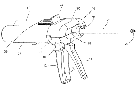
Figures 1 and 2 show a two-component blending gun 10. The blending gun 10 has
a
handle 12 with an actuation lever 14. The handle 12 has a receptacle 16 which
receives the
actuation lever 14 when in its depressed condition. The handle 121aterally is
further
provided with a lug 18 which can serve as an abutment for the thumb during an
actuation.
The two-component blending gun has a mixer 20 which internally exhibits
helically
shaped blending plates which are known as such and thoroughly blend the
components
which are advanced by them. The components, when blended together, exit
through the
mixer tip 22. The mixer 20 is selected in its diameter and its arrangement of
the guide plates
used in a manner known as such depending on the requirements made to the
components
being blended. The mixer 20 is screwed to a holder 26 by means of a spigot nut
24. The
holder 26 exhibits a head portion 28 which has an upper half 30 and a lower
half 32 which is
joined to the handle 12 (as shown in Figure 2). The holder 26 further exhibits
a supporting
plate 34 through which the actuation lever 14 is extended (cf. Figure 3). The
upper and lower
parts of the head portion 28 can be screwed to each other.
Referring back to Figure 1: The two-component blending gun which is shown
further
has a sleeve-like vessel receptacle 36 which accommodates two cylindrical
dispensing
vessels 38, 40. At its end facing the mixer 20, the vessel
CA 02525005 2005-11-01
-5-
receptacle 36 has a catch plate 42 which is fixed to a movable tongue 46 of
the
mounting 36 and can be moved via a lever 44 that stands out (cf. Figure 3).
For insertion, the dispensing vessels 38 and 40 are axially introduced into
the
receptacle 36 and are advanced until the catch plate 42 grips behind the valve
disks,
the rim of the vessel or another lug on the dispensing vessels. The vessels
will then
be in communication with the vessel receptacle 36. For an exchange of the
vessels
38 and 40 after use, the lever 44 is bent away from the mixer 20 to release
the cans
38 and 40.
As is apparent from Figures 3 and 4 the head portion 28 has provided thereon
connection means. The connection means illustrated comprises a blending body
46
which has two inlet openings 48, 50 for the valves of the vessels 38 and 40.
As will
be explained now the components are blended in the mixer only and not yet in
the
blending body. The components are fed to the mixer separately through the
blending
body. The inlet openings point towards the blending tube 20. The inlet channel
52
and 54 that respectively joins the inlet opening 48 and 50 has a check valve
56 and
58. The check valves 56 and 58 are introduced into the blending body through a
lateral opening to facilitate their assembly. The check valves concerned are
conically
converging membrane elements which have a slot which is opened by the medium
in
the direction of channel and is squeezed in the opposite direction.
Centrally interposed between channels 52 and 54 is a channel body 60 which
defines an extension of the two channels 52 and 54 towards the mixer. The
inserted
body 60 has a partition 62 which extends through the channel. For example, the
inserted body 60 may be held by lugs on that side of the blending body 46
which
faces away from the mixer.
The channel body 60 also serves as a gate for the mixer 20.
As can be seen distinctly in Figure 4 the vessel receptacle 36 has a groove 64
at its underside that opens into an abutting surface 66 at the side facing the
mixer.
The actuation lever 14 has a bore 70 through which the actuation lever 14 is
pivotally supported by a spigot 68 about the handle 12. A projection 72
extends into
the holder and bears on the abutting surface 66. Actuating the lever 14 causes
the
CA 02525005 2005-11-01
-6-
receptacle 36 to be moved towards the mixer via the projection 72 and abutting
surface 66. As a result, the projecting stem of the valves 74 and 78 urges the
vessels
38 and 40 into the receptacles 48 and 50. The valves of the vessels 38 and 40
will
open after a sufficient lift and the components will exit and get into the
mixer 20.
For guidance of the receptacle on the holder device the latter is laterally
provided with lugs 78 which are guided in an appropriate seat 80 on the head
portion
28.
Not illustrated is a second catch plate which substantially corresponds in
geometry to that of the catch plate 42 and is disposed opposite this one in
the vessel
receptacle 36. This enables the dispensing vessels 38 and 40 to be held in the
vessel
receptacle 36 for an application of an appropriate force. To prevent the catch
plate
42 from coming off incidentally it can be biased to its engaged position via a
leaf
spring 80. The leaf spring 80 is guided on the receptacle 36 via tracks 82 and
84.
In the embodiment which is shown, force is applied by the actuation lever
directly to the vessel receptacle for the dispensing vessels. An
intensification of the
force would also become possible by providing a transmission or gearing here.
The 2-component blending gun is preferably manufactured from a reinforced
plastic and is designed for permanent use. The lift to be provided is
different,
depending on the valve used. As a rule, a lift of two to three millimeters is
adequate
for standard valves. Tilting valves may be employed in addition to the axially
actuated valves which are shown. The design of the valves may vary as well
and,
thus, it is also possible to use so-called bag-on valves or valves having an
internal
pressure-guided piston.
Figure 6 shows two can-shaped vessels 160 and 162 each of which has a
projecting stem 164, 166. For example, the valve interacting with the stem may
be a
valve as is used for PU foam. The vessels 160 and 162 are held in parallel and
at the
same orientation to each other by means of a pair of vessel attachments 168
and 170.
Each vessel attachment is of a roughly bone-like shape with one receptacle
each for
the vessel. The substantially circular receptacles for the vessel ends are
joined to
each other via a bridging portion. The bridging portions have cruciform webs
172,
CA 02525005 2005-11-01
-7-
174. The vessel attachment 168 provided in the top region of the vessels has
an
abutting surface which is provided on the side facing away from the valves and
is for
an actuation device. This abutting surface can suitably be located
approximately at
the level of the longitudinal axis of the vessels 160, 162 so that this avoids
tilting the
vessels while they are advanced.
It is preferred to use a snap-in mechanism to join the vessel attachments 160
and 170 to the vessels 160 and 162. The vessel attachments are renewed
together
with the vessels in case of a replacement. The risk of confusing them may be
ruled
out by providing appropriate contours to the vessel attachments and the
holder.
As was the case for the vessel receptacle 136 already the vessel attachment
168 is slidably guided in the head portion 128 of the holder, which makes the
vessel
receptacle 136 unnecessary here.
In this aspect, a spring-loaded release lever may be provided which grips
behind the bridging portion. This also secures the inserted vessels from being
taken
out. For a detachment of the vessels with the vessel attachment, a solvent is
provided
which loosens the vessel attachment in the head portion of the holder so that
the
vessel attachment can be removed.
In a possible aspect, the two dispensing vessels are interconnected to form a
package already. An appropriate geometry of this package allows a suitable
receptacle or appropriate blending body to prevent a confused introduction of
the
vessels. Dispensing vessels can be provided in different volumes and with
different
valves, depending on the desired blending ratio. If dispensing vessels having
a rolled
rim are used the detent means preferably grip behind the rim.
An alternative aspect of a two-component blending gun 210 is shown in
Figures 8 and 9. Like the model described previously, the blending gun has a
handle
212 with a receptacle 216 for an actuation lever 214. Again, a lug 18 is
provided as
an abutment for the thumb. Like in the model which is known already, the mixer
220
is fixed to a holder 226 by means of a spigot nut 224.
As can be seen from Figure 10 the holder 226 is composed of a lower shell
half 228 and an upper shell half 230. The lower shell half 228 is joined to
the handle
CA 02525005 2005-11-01
-8-
212 and, at the side facing the handle, has an opening through which a
projection
272 of the actuation lever 214 extends into the interior. The upper shell half
230 may
be fixed, along with the lower shell half 228, by means of two pairs of screws
which
are guided in the lower shell half 228 via screw channels 229.
In addition to the upper shell half 230, a cover element 231 is provided
which engages both the upper shell half 230 and lower shell half 228 via
lateral
detent edges 233 and a detent projection 235. At its rear end, the cover 231
centrally
has a projection 237 with a catch nose 239. The projection 237 is passed
through
between the vessels 238 and 240 and additionally secures the cover element 231
to
the lower shell half 228.
The two vessels 238 and 240 are accommodated in a pair of vessel
attachments 268 and 270. The vessel's front attachment 268 is joined to either
of the
two vessels 238 and 240. The vessel attachment 268 has an annular indentation
with
detent means which snap into a circumferential lug along the valve disk. At
its
underside, the vessel adapter 268 has a recess into which the projection 272
of the
actuation lever 214 extends. During use, the actuation lever 214 is depressed
and the
force applied is transmitted to the upper vessel adapter. The vessels 238 and
240,
along with the lower vessel attachment 270, are thus moved towards the mixer
220.
The projecting stem of the valves extends through the vessel attachment 268
and into a blending body 246 which serves as a gate to the mixer. The
components
being mixed are separately fed to the mixer through the blending body.
Figure 11 shows a cross-section through the front portion of the blending
gun. The blending body 246 has two separate channels 252 and 254. The stems
248
and 250 are mounted in the blending body 246. So-called tilting valves which
will
also open when under an axial pressure are shown as valves in Figure 11.