Note: Descriptions are shown in the official language in which they were submitted.
CA 02525218 2005-11-08
WO 2004/105621 PCT/US2003/014691
ANASTOMOTIC STAPLE WITH FLUID DISPENSING CAPILLARY
BACKGROUND
1. Technical Field
The present disclosure relates to a surgical staple used for
performing an anastomosis of tubular body structures, and more particularly to
a
surgical staple which includes a capillary disposed thereon which is designed
to
expel a bonding agent or other medicament upon deformation of the staple.
2. Background of Related Art
Anastomosis is a surgical procedure for joining two tissues, e.g.,
vessels and tubular organs, for fluid communication therebetween. Generally,
anastomosis procedures can be categorized into two main types, coronary artery
bypass graft (CABG) procedures and gastrointestinal surgical procedures. A
CABG procedure restores blood flow to damaged or ischemic heart muscle
whose blood supply has been compromised by occlusion or stenosis of one or
more of the coronary arteries. Gastrointestinal anastomosis procedures such as
a low anterior resection of the colon are designed to alleviate colon cancer,
CA 02525218 2005-11-08
WO 2004/105621 PCT/US2003/014691
diverticular disease, gastrointestinal bleeding, inflammatory bowel disease,
intestinal polyps and large bowel obstruction.
One method for performing CABG surgery involves harvesting a
saphenous vein (or other venous or arterial vessel from elsewhere in the body)
and connecting the saphenous vein as a bypass graft from a viable artery, such
as the, aorta, to the coronary artery downstream of the blockage or narrowing.
Such procedures typically require that the heartbeat be arrested while
maintaining
circulation throughout the rest of the body. Cardioplegic fluid, such as
potassium
chloride (KCI) is delivered to the blood vessels of the heart to paralyze the
myocardium. Cardioplegic fluid is infused into the myocardium through the
coronary arteries by a catheter inserted into the ascending aorta.
Alternatively,
cardioplegic fluid is inf used through the coronary veins in a retrograde
manner by
a catheter positioned in the interior jugular vein accessed at the patient's
neck.
Such procedures require the introduction of multiple catheters into the blood
vessels adjacent the heart, which is a complicated procedure requiring that
the
desired vessels be properly located and accessed. The progression of the guide
wires and catheters must be closely monitored to determine proper placement.
Furthermore, the introduction of catheters form punctures in the blood vessels
that
must be subsequently closed, and there is an increased risk of trauma to the
interior walls of the vessels in which the catheters must pass.
-2-
CA 02525218 2005-11-08
WO 2004/105621 PCT/US2003/014691
Alternatively, the CABG procedure may be performed while the heart
is permitted to beat. Such a procedure is now commonly referred to as
minimally
invasive direct coronary artery bypass (MIDCAB) when performed through a
thoracotomy (when performed through a sternotomy, the procedure is commonly
called open coronary artery bypass (OP-CAB). A surgical instrument is used to
stabilize the heart and restrict blood flow through the coronary artery during
the
graft procedure. Special care must be given to procedures performed on a
beating
heart, e.g. synchronizing procedures to occur at certain stages in the cardiac
cycle, such as between heartbeats.
To perform a CABG procedure, the harvested vessel segment, such
as the saphenous vein, is grafted to the coronary artery by end-to-side
anastomosis. Typically, sutures are used to graft the vessel segments.
However,
conventional suturing is complicated by the use of minimally invasive
procedures,
such as the window approach, e.g., limited access and reduced visibility to
the
surgical site may impede the surgeon's ability to manually apply sutures to a
graft.
Additionally, it is difficult and time consuming to manually suture if the
CABG
procedure is being performed while the heart is beating as the suturing must
be
synchronized with the heart beat.
In order to reduce the difficulty of creating the vascular anastomoses
during either open or closed-chest CABG surgery, it would be desirable to
provide a
-3-
CA 02525218 2010-02-24
rapid means for making a reliable end-to-side or end-to-side anastomosis
between a
bypass graft or artery and the aorta or the other vessels of the heart. A
first approach
to expediting and improving anastomosis procedures has been through stapling
technology. Stapling technology has been successfully employed in many
different
areas of surgery for making tissue attachments faster and more reliable. The
greatest
progress in stapling technology has been in the area of gastrointestinal
surgery as
described below.
Anastomotic staplers are used commonly for end-to-end anastomosis,
side-to-side or end-to-side anastomosis for various coronary artery bypass
procedures
and gastrointestinal procedures. Surgical stapling devices for applying an
array of
staples or fasteners to tissue are well known in the art. For example,
surgical stapling
devices for applying an annular array of staples, as well as devices for
completing a
surgical anastomosis through the provision of anastomosis rings, are known in
gastric
and esophageal surgery, e.g., in classic or modified gastric reconstruction
typically
formed in an end-to-end, end-to-side, or side-to-side manner. Several examples
of
instruments are shown and described in commonly-owned U.S. Patent No.
7,204,843,
commonly-owned U.S. Patent No. 6,726,697 and commonly-owned
-4-
CA 02525218 2010-02-24
U.S. Patent No. 6,769,594. These devices generally include a circular array of
fasteners such as staples and an anvil member. The staples are deformed
against the
anvil member to complete the anastomosis.
In use in gastrointestinal surgery, the anvil is positioned within the
lumen of an organ such as the stomach, esophagus, or intestine and the tissue
is
pulled about and around the anvil member and tied off, e.g., by a purse string
suture,
ring mechanism or the like. The stapler assembly is then positioned within the
opposite end of the lumen and the tissue is pulled about and around the
stapler
assembly over the staple array and also tied off. At this point the tissue is
positioned
between the anvil and the stapler assembly. The anvil is typically slowly
retracted (or
advanced) to approximate the two tissue halves prior to deformation of the
staples
usually by virtue of a wing-nut and worm gear assembly which allows a surgeon
to
methodically advance the anvil towards the staple array to hold the tissue
between the
anvil and the stapler assembly. Many prior art devices also provide a visual
indicator
to signal the surgeon when the anvil has reached a firing position adjacent
the stapler
assembly. The surgeon then unlocks a safety device deform the staples against
the
anvil. As the staples are
25
-5-
CA 02525218 2005-11-08
WO 2004/105621 PCT/US2003/014691
expelled from the stapler assembly, a circular knife typically follows the
application
of the staples to excise unwanted tissue at the anastomosis site. The
instrument is
then removed from the lumen of the organ.
Since it is essential that each anastomosis provide a smooth, open
flow path for the blood and that the attachment be completely free of leaks,
there is
often a frequent need for re-suturing of the anastomosis to close any leaks
that are
detected once the site is tested. Leaks may be attribute to any number of
factors
one of which is slippage of the tissue along the staple after the anastomosis.
Commonly-owned U.S. Patent Serial No. 10/160,460 describes a retaining ring or
strap which is designed for use during an anastomosis which is designed to
prevent
slippage between the two luminal vessels after the anastomosis. The ring
maintains
a reliable and consistent anastomosis between the two luminal vessels after
the
surgical instrument is fired and the surgical fasteners are released.
A continuing need exists, however, for improved surgical instruments
and methods for performing remote anastomoses during both conventional and
minimally invasive procedures which reduce the likelihood of leaks due to
tissue
slippage.
-6-
CA 02525218 2005-11-08
WO 2004/105621 PCT/US2003/014691
SUMMARY
The present disclosure relates to a surgical fastener for use with an
anastomosis of two tissues. The surgical fastener is generally L-shaped and
includes a base leg and an upright leg. The base leg is selectively deformable
and includes a traumatic tip for piecing tissue and the upright leg includes a
prong
which preferably extends atraumatically against the tissue. The surgical
fastener
also includes a capillary disposed on the base leg which has a reservoir
defined
therein for retaining a liquid. The capillary (or capillaries) is designed to
rupture
upon deformation of the surgical fastener to dispense the liquid to the
anastomosis site. It is envisioned that many different staple design may be
used
with one or more capillaries disposed on the deformable portions thereof.
Which
are designed to rupture upon deformation to expel the liquid disposed therein.
In one embodiment, the liquid in the reservoir includes a bonding
agent, a medicinal agent and/or a therapeutic agent. Preferably, the medicinal
agents or therapeutic agents include: anti-coagulants, bio-adhesives,
coagulants;
antibiotics, sterilizing solutions, anti-inflammatory medication, inflammatory
medications; immuno-stimulating agents, antiviral agents and/or anti-rejection
medications. The bonding agent is preferably made from a material which
adheres to tissue upon curing. As can be appreciated from the present
-7-
CA 02525218 2005-11-08
WO 2004/105621 PCT/US2003/014691
disclosure, this staple design enables a bonding agent to be accurately and
efficiently delivered to the anastomotic site which may promote better
anastomoses between tissues, promote healing, reduce leakage at the tissue-to-
tissue site, and reduce infection.
In another embodiment, the reservoir includes a series of chambers
which each include a liquid disposed therein selected from the group
consisting of:
bonding agents, medicinal agents and therapeutic agents.
In yet another embodiment, the surgical fastener includes a base leg
of having first and second capillaries which are designed to sequentially
rupture
upon deformation. It is envisioned that the first capillary may include a
medicinal
agent and the second capillary may include a bonding agent or other agent.
Preferably, the capillaries are radially disposed along the base leg of the
surgical
fastener.
The present disclosure also relates to a surgical fastener for use
with a surgical instrument for performing an anastomosis between two tissues.
The surgical instrument includes a selectively enageable loading unit (e.g., a
single-use loading unit or "SULU") for supporting an array of surgical
fasteners
-8-
CA 02525218 2005-11-08
WO 2004/105621 PCT/US2003/014691
and an actuator (handle) for initiating deformation of the surgical fasteners.
Each
of the surgical fasteners includes a base leg and an upright leg. The base leg
is
selectively deformable and includes a tip for piecing tissue. At least one
capillary
is disposed on the base leg and includes a reservoir defined therein for
retaining a
liquid such as a bonding agent, medicinal agent and/or therapeutic agent. Each
of the capillaries is ruptures upon deformation to dispense the liquid to the
anastomosis site.
BRIEF DESCRIPTION OF THE DRAWINGS
Other objects and features of the present invention will become
apparent from the following detailed description considered in connection with
the
accompanied drawings. It should be understood, however, that the drawings are
designed for the purpose of illustration only and not as a definition of the
limits of the
invention.
An illustrative embodiment of the subject'surgical fastener is described
herein with reference to the drawings wherein:
Fig. 1 is a perspective view of a surgical instrument for use with a
surgical fastener in accordance with an embodiment of the present disclosure;
-9-
CA 02525218 2005-11-08
WO 2004/105621 PCT/US2003/014691
Fig. 2 is an enlarged, perspective view of the surgical fastener
according to the present disclosure showing a set of bonding agent capillaries
disposed on a base leg thereof;
Fig. 3 is an enlarged, side view of the surgical fastener of Fig. 2;
Fig. 4A is an enlarged, partial perspective view of a single use
loading unit (SULU) which is designed to support an array of surgical
fasteners
and which is designed for operative engagement with a working end of the
surgical anastomosis instrument ;
Fig. 4B is an enlarged perspective view of the SULU being loaded
onto an actuating assembly prior to firing.
Fig. 5 is a perspective view of the SULU with a first vessel inserted
therethrough;
Fig. 6 is perspective of the SULU with an end of the first vessel
everted over a distal end of the disposable unit being inserted into an
incision in a
second vessel;
Fig. 7 is an internal, perspective view of the second vessel with the
SULU and the everted first vessel shown inserted therein;.
Fig. 8 is a side cross-sectional view of the SULU and the everted first
vessel shown inserted within the second vessel in pre-firing position;
Fig. 9 is an enlarged, perspective view of the SULU and the surgical
fastener shown after firing;
-10-
CA 02525218 2005-11-08
WO 2004/105621 PCT/US2003/014691
Fig. 10A is an enlarged, perspective view of the SULU and the
surgical fastener shown after firing;
Fig. 10B is a greatly enlarged, perspective view of the surgical
fastener shown in a "stapled" configuration;
Fig. 11 is cross section of the two luminal vessels showing the
bonding agent retaining the surgical fastener in position after firing;
Fig. 12 is a view showing a completed anastomosis;
Fig. 13 shows a retaining ring for use with the surgical fastener;
Figs. 14-17 show a series of surgical fasteners being used during an
end-to-end anastomosis; and
Figs. 18A-18C are views showing alternate configurations for the
surgical fastener.
DETAILED DESCRIPTION
Preferred embodiments of the surgical fastener disclosed herein will
be described in terms of a surgical instrument used for coronary artery bypass
procedures wherein a vascular anastomosis is created by joining a section of a
harvested vessel, e.g., the saphenous vein, to bypass an occlusion in a
coronary
artery, e.g., the left anterior descending artery ("LAD"). Alternatively, the
presently disclosed surgical instrument may also be utilized in performing
anastomosis of other tubular luminal body structures, e.g., colon resection.
-11-
CA 02525218 2005-11-08
WO 2004/105621 PCT/US2003/014691
In the drawings and in the description which follows, the term
"proximal", as is traditional, will refer to the end of the apparatus which is
closer to
the user, while the term "distal" will refer to the end which is further from
the user.
Referring now in detail to the drawing figures in which like reference
numerals identify similar or identical elements, one embodiment of an
instrument
for use with a surgical fastener 200 according the to present disclosure is
shown
by way of example in Fig. 1 and is designated therein as surgical instrument
10.
As explained in more detail below, surgical instrument 10 includes two
principal
components, namely, an actuator assembly 20 and a disposable loading unit
("DLU") or a single use loading unit ("SULU") 100, which along with their
internal
working components, mechanically cooperate to deform the surgical fastener 200
to complete an anastomosis between two vessels, e.g., a saphenous vein 320
and an aorta 310 (Fig. 8). Surgical instrument 10 is preferably designed to
deform
an array of surgical fasteners 200.
Actuator assembly 20 includes a proximal end 24, a distal end 22
and a housing 26 defined therebetween for storing the internal working
components of the actuator assembly 20. Preferably, a plate 90 covers the
internal components of the actuator assembly 20 when assembled. Actuator
-12-
CA 02525218 2010-02-24
assembly 20 also includes a handle 12 which initiates firing of the surgical
instrument
and a spring-loaded thumb tab 30 for loading the SULU 100 onto the actuator
assembly 20 both of which will be explained in greater detail below.
Preferably, handle
12 is provided with an ergonomic surface which is contoured and configured to
be
5 comfortably gripped by the hand of the user during operation of the
instrument.
For the purposes herein, only the general operating features of the
surgical instrument 10 are described.
As best shown in Figs. 4A and 4B, the SULU 100 includes a first
retracting sleeve 110 and second retracting sleeve 120 which cooperate to
deform
fasteners 200 and securely fasten the saphenous vein 320 to the aorta 310 in
fluid
communication (see Fig. 11). More particularly, retracting sleeve 110 includes
a
circular lip 112 located at its proximal end and a semi-circular anvil 118
located at the
opposite end. Movement of the first retracting sleeve 110 deforms the surgical
fasteners 200. Movement of the second retracting 120 sleeve release the
surgical
-13-
CA 02525218 2010-02-24
fasteners 200. The operative details associated with the inter-cooperative
relationship
of the SULU 100 and the actuator assembly 20 are described in more detail with
respect to commonly-owned U.S. Patent No. 6,769,594. For the purposes herein,
only
a limited discussion of the working features of the SULU 100 and the actuator
assembly 20 is warranted.
As best seen in Fig. 4B, movement of tab 30 will expose carriages 86
and 88 disposed within a first retractor 80 in the distal end of the actuating
assembly.
The carriages 88 and 86 are designed to receive the first and second
retracting
sleeves 110 and 120, respectively. More particularly, carriage 86 is generally
circular
in shape and is designed to receive an outer lip 122 of second retracting
sleeve 120.
Carriage 88 is likewise circular in shape and receives outer lip 112 of the
first retracting
sleeve 110.
The SULU 100 is then loaded within actuator assembly 20 by placing lip
112 within carriage 88 and lip 122 within carriage 86. Lip 122 is positioned
near the
distal end of carriage 86 which allows lip 122 and, hence, second retracting
sleeve
120, to move independently from the first retracting sleeve to release the
surgical
fasteners after deformation. Once the SULU is
14
CA 02525218 2005-11-08
WO 2004/105621 PCT/US2003/014691
positioned within carriages 86 and 88, thumb tab 30 is released to lock the
SULU
100 within the actuator assembly 20.
As mentioned above, upon actuation of actuator assembly 20, the
first retractor 80 retracts the first retracting sleeve 110 which, in turn,
causes
surgical fasteners 200 to deform. More particularly, proximal movement of the
first
retractor 80 causes both the first retracting sleeve 110 and the second
retracting
sleeve 120 to move proximally relative to a biasing post 102 on the end of the
SULU 100. As a result, the anvil 118 deform the distal ends 235 of surgical
fasteners 200 upwardly and proximally towards a series of corresponding
support
braces 137 located on the SULU. The arc-like distal ends of the anvil 118
cause
surgical fasteners 260 to deform upwardly and proximally upon retraction of
the
first retracting sleeve 110. Fig. 10A illustrates the resulting deformation of
the
surgical fastener 200 through the two luminal structures 320 and 310.
Preferably, the opposite ends 235 and 230 of the surgical fasteners
200 are deformed at an angle a relative to one another as best shown in Fig.
10B.
This allows end 235 to deform proximal to braces 137. Preferably, braces 137
have a tapered cross section to further deform end 235 of surgical fastener
200
radially from end 230 during deformation.
-15-
CA 02525218 2005-11-08
WO 2004/105621 PCT/US2003/014691
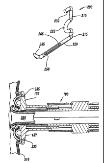
As best seen in Figs. 2 and 3, surgical fastener 200 is generally L-
shaped and includes a base leg 220 and an upwardly extending support leg 210.
Preferably, base leg 220 includes a distal end 235 which is sufficiently
shaped to
penetrate the saphenous vein 320 and aorta 310 upon deformation of the
surgical
fastener 200. The upwardly extending support leg 210 is attached to base leg
220
at a pivot point 215 and includes an inwardly extending prong 230 disposed at
its
free end designed to penetrate the aorta 310 and secure surgical fastener 200
in
position after anastomosis. It is envisioned that pivot point 215 may also be
dimensioned to include a relief or coined section (not shown) which will
facilitate
deformation of the surgical fastener 200.
A convexity 225 projects inwardly between the base leg 220 and the
support leg 210 and is preferably sufficiently dimensioned to cooperate with
the
base leg 220 to retain the saphenous vein 320 against aorta 310 in fluid
communication after anastomosis as will be explained in greater detail below.
It is
envisioned that the surgical fastener 260 can be arranged on the SULU in
different patterns/arrays depending upon a particular purpose.
Surgical fastener also includes a capillary 250a which extends along
base leg 220. Capillary 250a includes an internal reservoir design to retain a
bonding agent 255 therein. The term "bonding agent" is defined herein to
include
fluids and gels (e.g., hydrogels and gelatins), which having the ability to
bond two
-16-
e
CA 02525218 2005-11-08
WO 2004/105621 PCT/US2003/014691
tissues together under compression. As can be appreciated different bonding
agents with different bonding characteristics, e.g., strength, duration (as it
relates
to the biodegradability of the bonding agent), tackiness, curing attributes,
etc.
may be employed depending upon a particular purpose.
It is envisioned that the capillary 250a may contain one or more
reservoirs 257a-257c which contain one or more bonding agents 255 (or other
medicinal agents) depending upon a particular purpose (e.g., designed to
activate
upon mixing). In some instances it may be desirable to utilize more than one
capillary, e.g., 250b. Moreover, one of the capillaries 250a (or one of the
reservoirs 257a-257c in a single capillary system) may contain a bonding agent
255 and another, e.g., 250b may contain additional bonding agents or other
medicinal' agents or therapeutic agents such as: anti-coagulants, bio-
adhesives
(e.g., polymer-based, co-polymer based, organic compounds, barnacle-based,
plant-based, Progesterone-based, etc.), coagulants; antibiotics, sterilizing
solutions, anti-inflammatory medication, inflammatory medications (which may
help secure seal as explained in more detail below); immuno-stimulating
agents,
antiviral agents and/or anti-rejection medications.
The capillary (or capillaries) are designed to rupture upon
deformation of the surgical fastener 200 thereby releasing the bonding
agent(s)
atop and along each surgical fastener. Preferably, the capillary ruptures at
-17-
CA 02525218 2005-11-08
WO 2004/105621 PCT/US2003/014691
multiple locations along the length thereof to more evenly disperse the
bonding
agent along the surgical fastener 200. It is also envisioned that the
capillary can
be designed to rupture sequentially at multiple positions along the length
thereof
which would allow sequential mixing of bonding agents and/or other medicinal
agents.
As best illustrated in Figs. 10A-11, by design, the capillary 250 is
designed to rupture simultaneously upon deformation of the surgical fastener
200. As can be appreciated, this enables the bonding agent to dispense along
the
base leg 220 of the surgical fastener between the two tissues. Preferably, the
bonding agent 255 quickly cures to seal both the pierced areas of the tissues
and
secure the surgical fastener 200 to the tissues to prevent slippage. As
mentioned
above, the bonding agent 255 may be a composition of medicinal agents and
adhesives which promote healing and/or reduce the chances of infection around
the anastomotic site. In addition, it is envisioned that a bonding agent 255
may be
employed which slightly expands upon curing to facilitate sealing of the
pierced
tissues after firing.
As mentioned above and as best seen in Figs. 10A and 11, the
convexity 225 of the surgical fastener projects inwardly between the base leg
220
and the support leg 210 to retain the saphenous vein 320 against aorta 310 in
fluid communication after anastomosis. More particularly, after deformation of
the
-18-
CA 02525218 2010-02-24
surgical fastener 200, the convexity 225 is designed to assert a consistent
pressure
against the aorta 310 to squeeze the two tissues 310 and 320 into tight
abutment with
one another.
It is envisioned that the surgical fastener 200 can be other or more
conventional shapes to enhance anastomosis between the two tissues 310 and
320.
For example, Figs. 18a-18c show configurations for various surgical fasteners
which
may include one or more capillaries which when deformed expel a bonding agent
therefrom.
A retaining ring or strap may also be utilized to maintain a consistent
anastomosis between the two luminal vessels 310 and 320 after the SULU 100 is
fired
and the surgical fasteners 200 are released (see Fig. 13). More particularly,
retaining
ring includes a series of alternating loops and arcuate portions which are
formed
radially about the ring. Each loop defines an aperture therein which is
dimensioned to
receive the distal end 235 of a surgical fastener 200. Several examples of
retain rings
and straps are disclosed in U.S. Patent 6,769,594.
Turning now in detail to the operation of the surgical instrument 10 and
in particular, the operation of the SULU 100 as detailed in Figs. 5-10B, once
the
saphenous vein 310 has been harvested, the user inserts the free end 322
19
CA 02525218 2005-11-08
WO 2004/105621 PCT/US2003/014691
into opening 133 of the SULU 100 and pulls (via a surgical hook or graspers)
the
free end 322 towards the distal end of the SULU 100. The user then everts the
saphenous vein 320 over the anvil 118 of the SULU 100 such that the free end
322 of the saphenous vein 320 is retained by end 235 of the surgical fasteners
200. Everting of the saphenous vein 320 may be achieved by any suitable known
instruments and/or techniques such as by using graspers.
The remaining portion of the saphenous vein 320 is preferably
positioned away from the instrument 10 to facilitate insertion of the
saphenous
vein 320 into the aorta 310 as shown in Figs. 6 and 7. The user then inserts
the
end of the SULU 100 into an incision 312 in the aorta 310 such that the distal
end
235 of each of the plurality of fasteners 200 and the everted end portions 322
of
the saphenous vein 320 are sufficiently inserted into and through incision 312
(Figs. 7 and 8). As seen best in the enlarged view of Fig. 8, the support leg
210,
convexity 225 and prong 230 of each surgical fastener 200 remains outside
incision 312. The instrument is now preset for firing.
When the handle 12 is depressed by the user, it ultimately moves
the retractor 80 proximally to retract the first retracting sleeve 110 which,
in turn,
causes surgical fasteners 200 to deform as shown in Figs. 9 - 10B. More
particularly, proximal movement of the first retractor 80 causes both the
first
-20-
CA 02525218 2005-11-08
WO 2004/105621 PCT/US2003/014691
retracting sleeve 110 and the second retracting sleeve 120 to move proximally
relative to biasing post 102. As a result, anvil 118 deforms the distal ends
235 of
surgical fasteners 200 upwardly and proximally towards brace 137. At the same
time, the aorta 310 is forced slightly proximally and extending prongs 230
penetrate to hold the aorta 310 in position as best seen in Fig. 10A. As
mentioned
above, the opposite ends 235 and 230 of the surgical fasteners 200 are
deformed
at an angle a relative to one another which allows end 235 to deform
proximally
past braces 137. Fig. 12 shows a completed anastomosis.
In use, surgical instrument 10 facilitates the performance of a
vascular anastomosis and either eliminates and/or minimizes the need for
manual
suturing of the vessels. Although the uses described herein will be addressed
in
terms of vascular anastomosis performed on a beating heart, the presently
disclosed surgical instrument 10 and surgical fastener 200 may also be used in
performing anastomoses of other tubular or luminal body structures without
departing from the scope herein. For example, surgical instrument 10 may be
used in conventional open CABG procedures using a median sternotomy or other
large incision without stopping the heart. Alternatively, the thoracic
"window"
procedure may be used to achieve access to the heart. The "window" approach
involves a smaller incision and less displacement of the ribs, and therefore
is less
traumatic to the patient. For this approach, conventional surgical techniques
are
used to determine the location of the incision to access the chest cavity.
-21 -
CA 02525218 2005-11-08
WO 2004/105621 PCT/US2003/014691
To gain access to the heart, after an incision is made, a surgical
retractor assembly may be used to separate the ribs at the site of the
incision.
Specifically, the retractor assembly is mounted on a base and used to retract
ribs
until a sufficiently large opening in the chest cavity is defined to provide
direct
access to the heart. For example, the sternum and the fourth and fifth ribs
can be
split apart to create a window. Other configurations of spreading the ribs
and/or
selectively cutting individual ribs away from the sternum may also be utilized
for a
particular procedure.
Once the desired access to the heart is achieved, the graft vessel,
e.g., the saphenous vein 320 is dissected and harvested from the leg, and a
free
end of the vessel is exposed. The occluded coronary artery, e.g., the LAD 310,
is
then prepared for receiving the saphenous vein 320 graft. The heart is
positioned
in the desired orientation either by traction sutures passing through the
pericardium or by manipulation with heart manipulation instruments which are
held
by the surgical personnel or clamped in a fixed orientation to a base such as
the
retractor assembly base. Blood flow through the aorta 310 can be restricted by
cardiopulmonary bypass and pericardial cooling. Alternatively, a dampening
instrument may be applied directly on the aorta 310 to restrict blood flow and
reduce movement of the heart near the aorta 310.
-22-
CA 02525218 2010-02-24
Continual movement of the handle 12 after deformation of the surgical
fasteners 200, moves the second retracting sleeve 120 within carriage 86
relative to
the first retracting sleeve 110. Proximal movement of the second retracting
sleeve 120
releases the surgical fasteners 200 after deformation. A more detailed
explanation
relating to the release of the surgical fasteners is disclosed in U.S. Patent
No.
6,769,594.
Figs. 14-17 show the presently disclosed staple for use with an end-to-
end anastomosis. More particularly, the user inserts a free end 322 of the
first luminal
structure, e.g., intestine, into opening 133 of the SULU and pulls via a
surgical hook or
graspers the free end 322 towards the distal end of the SULU 100. The user
then
everts the first luminal structure 320 over the anvils 118 of the SULU 100
such that the
free end 322 is retained by end 235 of the surgical fasteners 200 (see Fig.
14).
Everting of the first luminal structure 320 may be achieved by any suitable
known
instruments and/or techniques such as by using graspers. The first luminal
structure
320 is preferably everted over the full length of the base leg 220 such that
the first
luminal structure 320 resides in close proximity to convexity 225 as best seen
in FIG.
15.
-23-
CA 02525218 2005-11-08
WO 2004/105621 PCT/US2003/014691
The first luminal structure 320 may then secured to the distal end of
the SULU 100 by a suture or other convention means or by virtue of an
additional
securing mechanism (not shown) disposed on the SULU 100. The user then
inserts the end of the SULU 100 and the first luminal structure 320 into the
second
luminal structure 310 such that the distal end 255 of each of the plurality of
fasteners 200 and the everted end portions 322 of the first luminal structure
320
are sufficiently inserted into end 312 (Fig. 15). The support leg 210,
convexity 225
and prong 230 of each surgical fastener 200 remains outside opening 312. The
instrument is now preset for firing.
Much in a similar manner as described above, when the handle 12
is actuated by the user, it ultimately moves the retractor 80 proximally to
retract
the first retracting sleeve 110 which, in turn, causes surgical fasteners 200
to
deform as shown in Fig. 16. More particularly, proximal movement of the first
retractor 80 causes both the first retracting sleeve 110 and the second
retracting
sleeve 120 to move proximally relative to biasing post 102. As a result, anvil
118
deforms the distal ends 235 of surgical fasteners 200 upwardly and proximally
towards brace 137. At the same time, the aorta 310 is forced slightly
proximally
and extending prongs 230 penetrate to hold the aorta 310 in position as best
seen
in Fig. 16. As mentioned above, the opposite ends 235 and 230 of the surgical
fasteners 200 are deformed at an angle a relative to one another which allows
end
-24-
CA 02525218 2005-11-08
WO 2004/105621 PCT/US2003/014691
235 to deform proximally past braces 137. Fig. 17 shows a completed
anastomosis.
As mentioned above, the first retractor 80 retracts the first retracting
sleeve 110 (FIG. 21) which, in turn, causes surgical fasteners 260 to deform
as
shown in FIGS. 21 B and 21 D. More particularly and as best shown in FIG. 21
B,
proximal movement of the first retractor 80 causes both the first retracting
sleeve
110 and the second retracting sleeve 120 to move proximally relative to
biasing
post 102 until biasing post 102 abuts the end 69 of elongated stop 65. As a
result, anvils 11 8a and 11 8b deform the distal ends 269 of surgical
fasteners 260
upwardly and proximally towards braces 137a and 137b, respectively, i.e., arc-
like
distal ends 184a and 184b cause surgical fasteners 260 to deform upwardly and
proximally upon retraction of the first retracting sleeve 110. At the same
time, the
second luminal structure 310 is forced slightly proximally and extending
prongs
267 penetrate to hold the second luminal structure 310 in position as best
seen in
FIG. 22A. FIG. 26 illustrates the resulting deformation of clip 260 through
the two
luminal structures 320 and 310.
It is anticipated that the radially offset orientation of the opposite
ends 186a, 186b and 184a, 184b of the support channels 119a and 119b,
respectively will cause the opposite ends 267 and 269 of the surgical
fasteners
-25-
CA 02525218 2010-02-24
260 to deform at an angle a relative to one another as best shown in FIG. 21
D. This
allows end 269 to deform proximal to braces 137a and 137b. Preferably, braces
137a
and 137b have a tapered cross section to deform end 269 of surgical fastener
260
radially from end 267 during deformation.
It is anticipated that the presently disclosed surgical fasteners 260 can
also include an end 269 which is blunt and which does not penetrate the
luminal
structures 320 or 310 upon deformation. As can be appreciated, this offers the
user
the option of performing a less traumatic anastomosis.
Figs. 18A-18C show configurations for various surgical fasteners which
may include one or more capillaries which when deformed expel a bonding agent
therefrom.
From the foregoing and with reference to various figure drawings, those
skilled in the art will appreciate that certain modifications can also be made
to
25
-26-
CA 02525218 2005-11-08
WO 2004/105621 PCT/US2003/014691
the present disclosure without departing from the scope of the same. For
example,
it may be preferable to position the capillaries 250 at different locations on
the
surgical fasteners 200 depending upon a particular purpose or to achieve a
particular result. Moreover, at least one of the ends of one or more surgical
fasteners may include a plurality of tips for piercing tissue. In addition,
one of the
end of the surgical fastener, e.g., 235, may be traumatic, while the other end
may
be atraumatic (i.e., does not pierce tissue). Alternatively, both ends of the
surgical
fastener 235 may be atraumatic.
_. -t i :
It is also envisioned that the surgical fastener 200 may include two or
more capillaries 250a, 250b which are radially disposed along the length of
the base
member 220.
It will be understood that various modifications may be made to the
embodiments shown herein. For example, the instrument may be sized. to
perform an anastomosis for other vessels and luminal tissue, e.g., intestine,
bowel, colon, etc. Therefore, the above description should not be construed as
limiting, but merely as exemplifications of preferred embodiments. Those
skilled
in the art will envision other modifications within the scope and spirit of
the claims
appended hereto.
-27-