Language selection

Search

Patent 2525352 Summary

Third-party information liability

Some of the information on this Web page has been provided by external sources. The Government of Canada is not responsible for the accuracy, reliability or currency of the information supplied by external sources. Users wishing to rely upon this information should consult directly with the source of the information. Content provided by external sources is not subject to official languages, privacy and accessibility requirements.

Claims and Abstract availability

Any discrepancies in the text and image of the Claims and Abstract are due to differing posting times. Text of the Claims and Abstract are posted:

  • At the time the application is open to public inspection;
  • At the time of issue of the patent (grant).
(12) Patent: (11) CA 2525352
(54) English Title: ADJUSTABLE ELECTRICAL OUTLET BOX
(54) French Title: BOITE DE PRISE DE COURANT AJUSTABLE
Status: Granted
Bibliographic Data
(51) International Patent Classification (IPC):
  • H02G 3/08 (2006.01)
  • H02G 3/12 (2006.01)
(72) Inventors :
  • LALANCETTE, DANIEL (Canada)
(73) Owners :
  • THOMAS & BETTS INTERNATIONAL, INC. (United States of America)
(71) Applicants :
  • THOMAS & BETTS INTERNATIONAL, INC. (United States of America)
(74) Agent: MACRAE & CO.
(74) Associate agent:
(45) Issued: 2011-07-05
(22) Filed Date: 2005-11-03
(41) Open to Public Inspection: 2006-05-22
Examination requested: 2005-11-03
Availability of licence: N/A
(25) Language of filing: English

Patent Cooperation Treaty (PCT): No

(30) Application Priority Data:
Application No. Country/Territory Date
60/630,005 United States of America 2004-11-22

Abstracts

English Abstract


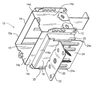
The present invention is directed to an electrical outlet box assembly for
adjustable positioning with respect to a wall stud. An electrical outlet box
includes plural side
walls defining a box interior having an open front face. A box locator is
adjustably positioned on
one of the side walls so as to adjust the location of the front face with
respect to the stud to which
the box locator is mounted. A support bracket is adjustably attached to
another of the side walls
for supporting the adjustably positioned box with respect to the back wall
board.


French Abstract

La présente invention a trait à un ensemble de boîte de prise de courant pour le positionnement ajustable par rapport à un poteau mural. Une boîte de prise de courant comprend plusieurs parois latérales définissant l'intérieur d'une boîte possédant un devant ouvert. Un box localisateur de boîte est placé de manière ajustable sur une des parois latérales, de manière à ajuster l'emplacement du devant par rapport au poteau mural auquel le localisateur est monté. Un support de montage est fixé de manière ajustable à une autre des parois latérales pour supporter la boîte placée de manière ajustable par rapport à la paroi arrière.

Claims

Note: Claims are shown in the official language in which they were submitted.


WHAT IS CLAIMED IS:


1. An electrical outlet box assembly for adjustable positioning with respect
to a wall
stud comprising:
an electrical outlet box having plural side walls defining a box interior
having an
open front face;
a box locator adjustably positioned on one of said side walls, said box
locator
having a mounting surface portion parallel to said open front face of said box
and an
attachment surface perpendicular thereto, said attachment surface including a
pair of rails
to adjustably position said box locators along said one side wall so as to
adjust the
location of said front face with respect to said stud, said attachment surface
being fixable
to said one side wall upon adjustable positioning of said front face of said
box with
regard to said stud; and
a support bracket including one side and two perpendicular sides extending
from
either end of said one side, said one side being adjustably attached to
another of said side
walls for supporting said adjustably positioned box with respect to said stud.


2. An adjustable electrical outlet box of claim 1, wherein said box locator is
screw
attached to said side wall.


3. An adjustable electrical outlet box of claim 2, wherein said screw
attachment is
achieved through said box interior.


4. An electrical outlet box assembly for adjustable positioning with respect
to a wall
stud comprising:
an electrical outlet box having a back wall, a pair of opposed bottom walls
and a
pair of opposed side walls defining an interior volume therebetween;
an extending compartment attached to each of said pair of opposed side walls
defining first extending compartment and second extending compartment, said
extending
compartments increase said interior volume;


8


an adjustable box locator slidably attached to said first extending
compartment;
and
a support bracket adjustably attached to said second extending compartment.


5. An electrical outlet box assembly of claim 4, wherein said box locator is a
right
angled member having an attachment surface and a mounting surface
perpendicular
thereto, said attachment surface is slidably attached to said first extending
compartment.

6. An electrical outlet box assembly of claim 5, wherein said first extending
compartment further including a pair of rails which slidably attaches said
first extending
compartment to said box locator.


7. An electrical outlet box assembly of claim 6, wherein said attachment
surface of
said box locator further includes protrusions to prevent dislodgment of the
box locator
from said pair of rails.


8. An electrical outlet box assembly of claim 7, wherein said support bracket
includes a pair of opposed right angled stop members and an elongated body
therebetween.


9. An electrical outlet box assembly of claim 8, wherein said elongated body
having
a central elongated slot and an attachment screw therethrough to attach said
support
bracket to said second extending compartment.


10. An electrical outlet box assembly for adjustable positioning with respect
to a wall
stud comprising:
an electrical outlet box having a back wall and a pair of opposed side walls;
an extending compartment attached to each of said pair of opposed side walls
defining first extending compartment and second extending compartment;
an adjustable box locator having an attachment surface and a mounting surface
perpendicular to said attachment surface, said attachment surface is slidably
attached to

9


said first extending compartment, said first extending compartment further
including a
pair of rails which slidably attaches said first extending compartment to said
box locator,
said attachment surface of said box locator further includes protrusions to
prevent
dislodgment of the box locator from said pair of rails; and
a support bracket includes a pair of opposed right angled stop members and an
elongated body therebetween, said elongate body having a central elongated
slot and an
attachment screw therethrough to adjustably attach said support bracket to
said second
extending compartment, said second extending compartment further including a
pair of
rails to engage with said support bracket providing adjustable attachment
thereto.


Description

Note: Descriptions are shown in the official language in which they were submitted.


CA 02525352 2008-06-06

ADJUSTABLE ELECTRICAL OUTLET BOX
FIELD OF THE INVENTION

[0002] The present invention relates generally to an electrical outlet box
mounted to a
wall stud. More particularly the present invention relates to an electrical
outlet box which may
be adjustably mounted to the wall stud so as to accurately position the outlet
box with respect to
the wall stud.

BACKGROUND OF THE INVENTION

[0003] Electrical outlet boxes are widely used to house electrical components
such as
switches and receptacles for termination of electrical wires run through the
wall of a structure.
Typically, these electrical outlet boxes are mounted to a wall stud supporting
structural wall
board. In new construction, the outlet box is mounted to the wall stud prior
to attachment of the
wall board. Thus, the outlet box must be properly positioned with respect to
the stud so that the
front face of the outlet box is aligned with the front of the wall board once
it is placed against the
stud. Such positioning of the box must be taken into consideration for the
various thickness and
layers of wall board.


CA 02525352 2008-06-06

[0004] In addition to such accurate mounting, subsequent electrical
termination of the
switches and receptacles in the box may cause the box to be moved or displaced
once secured.
In certain situations, there may be a tendency for the electrical installer to
push the box inwardly
into the wall cavity rendering the box useless.

[0005] The art has seen a number of brackets which are used in combination
with stud
mounted electrical boxes to both accurately align the front face of the outlet
box with respect to
the wall board and to prevent the box from being pushed into the wall cavity.

[0006] U.S. Patent No. 4,978,092 shows an adjustable support bracket that
prevents the
box from being pushed into the wall cavity.

[0007] U.S. Patent No. 2,473,051 also shows a box having an adjustable support
preventing the box from being pushed into the cavity.

[0008] U.S. Patent Nos. 5,289,934; 5,253,831 and 3,834,658 show adjustable
stud
mounted brackets which allow the box to be adjustably positioned with respect
to the wall stud.
[0009] None of the prior art devices, however, allow both for adjustment of
the box once
the box is attached to the wall stud, as well as providing separate
independent structure to

prevent the adjusted box from being pushed into the wall cavity.
SUMMARY OF THE INVENTION

2


CA 02525352 2005-11-03

[0010] The present invention provides an electrical outlet box assembly for
adjustable
positioning with respect to a wall stud. An electrical outlet box includes
plural side walls
defining a box interior having an open front face. A box locator is adjustably
positioned on one
of the side walls. The box locator includes a mounting surface parallel to the
open front face of
the box and an attachment surface perpendicular thereto. The attachment
surface is adjustably
positioned along one of the side walls so as to adjust the location of the
front face with respect to
the stud to which the box locator is mounted. The attachment surface is
fixable to the side wall
upon adjustable positioning of the front face of the box. A support bracket is
provided. The
support bracket is adjustably attached to another of the side walls for
supporting the adjustably
positioned box with respect to the back wall board.

BRIEF DESCRIPTION OF THE DRAWINGS

[0011] Figures 1 and 2 are perspective opposite side showings of adjustable
electrical
outlet box of the present invention.

[0012] Figures 3-5 show the adjustable electrical outlet box of Figure 1
accommodating
various thicknesses and numbers of wall board.

DETAILED DESCRIPTION OF THE PREFERRED EMBODIMENT

[0013] The present invention provides an electrical outlet box for supporting
electrical
components such as switches and receptacles (not shown). In conventional
fashion, the stripped
ends of insulated wires (not shown) are run into the box so as to be
terminated to the components
mounted within the box. The box itself is designed to be secured to a wall
stud such that when

3


CA 02525352 2005-11-03

wall board is placed over the wall stud, the front face of the box is
positioned generally flush
thereto.

[0014] Referring now to Figures 1 and 2, the electrical outlet box 10 of the
present
invention is shown. Box 10 includes a back wall 12, perimetrical side 14
including top and
bottom walls 14a and 14b and opposed lateral side walls 14c and 14d. The box
defines a box
interior 15 where the components are terminated and supported. Each of the
side walls 14c and
14d includes an extending compartment 16 so as to increase the interior volume
of box 10.
[0015] The extending compartments 16 define extending forward surfaces 16a
which are
generally parallel to the open front face 15a of box 10. As will be described
in further detail
herein below, the surfaces 16a are used to support wall board so that the
front face 15a of the box
may be positioned flush thereto.

[0016] Referring specifically to Figure 1, box 10 includes an adjustable box
locator 20
which is slidably attached to the side of compartment 16. The box locator 20
is generally a right
angled member having a mounting surface 22 positioned generally parallel to
front face 15a and
an attachment surface 24 perpendicular thereto. The attachment surface 24 is
held to
compartment 16 by a pair of rails 25 which slidably accommodate attachment
surface 24. The
distal edges of attachment surface 24 may include protrusions 24a to prevent
dislodgement of the
locator from the box. The box locator 20 allows the box 10 to be adjustably
positioned with
respect to a wall stud as will be described in further detail herein below.

4


CA 02525352 2008-06-06

[0017] Referring now to Figure 2, a support bracket 30 is adjustably attached
to
compartment 16 on the opposite side wall 14d of box 10. Support bracket 30
includes an
elongate body 32 having right angled stop members 34 and 36 extending from the
ends thereof.
Body 32 has a central elongate slot 33 through which an attachment screw 35
extends so as to
attach the support bracket to the compartment 16. The box is slidably coupled
to compartment
16 by a pair of rails 38 so that the support bracket 30 can be slidably
adjustably positioned along
compartment 16. As will be described in further detail herein below, the
support bracket 30 is
adjustably positioned so that stop 36 abuts against the inside of wall board
and stop 34 is
positioned adjacent the opposed wall board to prevent the box from being
pushed into the wall
during use.

[0018] Having described the components of the adjustable box of the present
invention,
its use may be described with respect to Figures 3-5.

[0019] As shown in Figure 3, the box 10 of the present invention may be
supported to a
wall stud 40 in such a manner that it accommodates a single thickness of 1/2"
wall board 50.
The box is installed on the stud in the following manner. The mounting surface
22 of box
locator 20 is secured to the face 40a of the stud using a conventional
mounting screw 60. The
box 10 is then adjustably positioned by slidable movement of the box with
respect to the locator
20 such that the front face 15a of the box extends approximately 7/16" from
the face 40a of the
stud. Once the box is properly positioned, a second screw 60 may be installed
through the
interior 15 of the box and through the attachment surface 24 to fix the
position of the box with
respect to the stud. The wall board 50 may now be attached to the stud 40. A
ledge 16a formed


CA 02525352 2005-11-03

by compartment 16 serves to seat the wall board 50. In this position, the
front face 15a of the
box is fixed at a position nearly flush with the wall board. Once the position
of the front face of
the box is fixed, support bracket 30 may be slidably positioned with respect
to wall board 50.
The attachment screw 35 is loosened so that the support bracket 30 can be
slidably adjustably
positioned along the box. The bracket 30 is positioned such that stop 36 is
slidably positioned
against wall board 50. The length of the support member is selected such that
when properly
positioned, the opposite stop 34 will be positioned next adjacent the wall
board (not shown)
which is attached to the opposite face 40b of stud 40. In this manner, during
use and installation,
and subsequently upon reattachment of components to box 10, the box will not
be pushed into
the wall.

[0020] Figure 4 shows a similar mounting technique for box 10 employed with
two
layers of 1/2" wall board 50. In this embodiment, the box 10 is adjusted such
that the front face
15a thereof is aligned substantially flush with the outer wall board surface
at a distance of
approximately 15/16" from face 40a of stud 40. The wall boards 50a and 50b are
attached to the
stud 40 such that the outer wall board 50a is positioned over ledge 16a of
compartment 16 while
the inner wall board 50b is positioned rearwardly and to the side of
compartment 16. The
bracket 30 is adjusted so that the stop 36 abuts against the inner surface of
wall board 50b. In
this position, opposed stop 34 abuts against the wall board attached to the
face 40b of stud 40 to
prevent the box from being inadvertently pushed into the wall during use.

[0021] As shown in Figure 5, box 10 may also be used to accommodate multiple
layers
of different thicknesses of wall board. For example, in Figure 5, wall board
50 which is 1/2"

6


CA 02525352 2005-11-03

wall board is combined with wall board 52 which is 3/4" wall board. In this
embodiment, the
front face 15a of box 15 is positioned approximately 15/16" from the face 40a
of stud 40. The
adjustable positioning of both the box locator 20 and the support bracket 30
accommodate this
combination by adjustment in a manner similar to that described with respect
to Figures 3 and 4.
[0022] Furthermore, it is contemplated that the present invention can be used
with a
variety of wall board thicknesses as well as a variety of multiples of wall
board layer. In each
case, the box is adjustably positioned with respect to box locator 20 so as to
position the front
face 15a of box 10 substantially flush with the outer surface of the wall
board. In the same
manner, support bracket 30 can be adjustably positioned so as to prevent the
box during use from
being pushed into the wall.

7

Representative Drawing
A single figure which represents the drawing illustrating the invention.
Administrative Status

For a clearer understanding of the status of the application/patent presented on this page, the site Disclaimer , as well as the definitions for Patent , Administrative Status , Maintenance Fee  and Payment History  should be consulted.

Administrative Status

Title Date
Forecasted Issue Date 2011-07-05
(22) Filed 2005-11-03
Examination Requested 2005-11-03
(41) Open to Public Inspection 2006-05-22
(45) Issued 2011-07-05

Abandonment History

There is no abandonment history.

Maintenance Fee

Last Payment of $473.65 was received on 2023-10-24


 Upcoming maintenance fee amounts

Description Date Amount
Next Payment if standard fee 2024-11-04 $624.00
Next Payment if small entity fee 2024-11-04 $253.00

Note : If the full payment has not been received on or before the date indicated, a further fee may be required which may be one of the following

  • the reinstatement fee;
  • the late payment fee; or
  • additional fee to reverse deemed expiry.

Patent fees are adjusted on the 1st of January every year. The amounts above are the current amounts if received by December 31 of the current year.
Please refer to the CIPO Patent Fees web page to see all current fee amounts.

Payment History

Fee Type Anniversary Year Due Date Amount Paid Paid Date
Request for Examination $800.00 2005-11-03
Registration of a document - section 124 $100.00 2005-11-03
Application Fee $400.00 2005-11-03
Maintenance Fee - Application - New Act 2 2007-11-05 $100.00 2007-10-19
Maintenance Fee - Application - New Act 3 2008-11-03 $100.00 2008-10-21
Maintenance Fee - Application - New Act 4 2009-11-03 $100.00 2009-10-22
Maintenance Fee - Application - New Act 5 2010-11-03 $200.00 2010-10-20
Final Fee $300.00 2011-04-18
Maintenance Fee - Patent - New Act 6 2011-11-03 $200.00 2011-10-17
Maintenance Fee - Patent - New Act 7 2012-11-05 $200.00 2012-10-17
Maintenance Fee - Patent - New Act 8 2013-11-04 $200.00 2013-10-17
Maintenance Fee - Patent - New Act 9 2014-11-03 $200.00 2014-10-08
Maintenance Fee - Patent - New Act 10 2015-11-03 $250.00 2015-10-14
Maintenance Fee - Patent - New Act 11 2016-11-03 $250.00 2016-10-12
Maintenance Fee - Patent - New Act 12 2017-11-03 $250.00 2017-10-11
Maintenance Fee - Patent - New Act 13 2018-11-05 $250.00 2018-10-11
Maintenance Fee - Patent - New Act 14 2019-11-04 $250.00 2019-10-09
Maintenance Fee - Patent - New Act 15 2020-11-03 $450.00 2020-10-15
Maintenance Fee - Patent - New Act 16 2021-11-03 $459.00 2021-10-25
Maintenance Fee - Patent - New Act 17 2022-11-03 $458.08 2022-10-24
Maintenance Fee - Patent - New Act 18 2023-11-03 $473.65 2023-10-24
Owners on Record

Note: Records showing the ownership history in alphabetical order.

Current Owners on Record
THOMAS & BETTS INTERNATIONAL, INC.
Past Owners on Record
LALANCETTE, DANIEL
Past Owners that do not appear in the "Owners on Record" listing will appear in other documentation within the application.
Documents

To view selected files, please enter reCAPTCHA code :


To view images, click a link in the Document Description column. To download the documents, select one or more checkboxes in the first column and then click the "Download Selected in PDF format (Zip Archive)" or the "Download Selected as Single PDF" button.

List of published and non-published patent-specific documents on the CPD .

If you have any difficulty accessing content, you can call the Client Service Centre at 1-866-997-1936 or send them an e-mail at CIPO Client Service Centre.


Document
Description 
Date
(yyyy-mm-dd) 
Number of pages   Size of Image (KB) 
Abstract 2010-11-05 1 14
Cover Page 2006-05-15 1 39
Abstract 2005-11-03 1 14
Description 2005-11-03 7 233
Claims 2005-11-03 3 91
Drawings 2005-11-03 4 59
Representative Drawing 2006-04-25 1 12
Description 2008-06-06 7 233
Claims 2009-05-22 3 96
Claims 2010-09-16 3 101
Cover Page 2011-06-07 2 43
Prosecution-Amendment 2009-06-12 2 53
Prosecution-Amendment 2007-12-06 2 67
Prosecution-Amendment 2010-03-16 2 91
Assignment 2005-11-03 3 106
Prosecution-Amendment 2008-12-01 2 79
Prosecution-Amendment 2008-06-06 6 230
Correspondence 2011-04-18 1 30
Prosecution-Amendment 2009-05-22 5 178
Prosecution-Amendment 2010-09-16 9 288