Language selection

Search

Patent 2525377 Summary

Third-party information liability

Some of the information on this Web page has been provided by external sources. The Government of Canada is not responsible for the accuracy, reliability or currency of the information supplied by external sources. Users wishing to rely upon this information should consult directly with the source of the information. Content provided by external sources is not subject to official languages, privacy and accessibility requirements.

Claims and Abstract availability

Any discrepancies in the text and image of the Claims and Abstract are due to differing posting times. Text of the Claims and Abstract are posted:

  • At the time the application is open to public inspection;
  • At the time of issue of the patent (grant).
(12) Patent: (11) CA 2525377
(54) English Title: BOAT STORAGE AND CONTAINER UNIT
(54) French Title: CONTENEUR D'ENTREPOSAGE ET DE CONFINEMENT A BORD D'UN BATEAU
Status: Deemed expired
Bibliographic Data
(51) International Patent Classification (IPC):
  • B63B 29/04 (2006.01)
  • B63B 25/00 (2006.01)
(72) Inventors :
  • HATTON, GRANT (Canada)
(73) Owners :
  • HATTON, GRANT (Canada)
(71) Applicants :
  • HATTON, GRANT (Canada)
(74) Agent: BLANEY MCMURTRY LLP
(74) Associate agent:
(45) Issued: 2008-07-29
(22) Filed Date: 2005-11-04
(41) Open to Public Inspection: 2007-05-04
Examination requested: 2007-04-12
Availability of licence: N/A
(25) Language of filing: English

Patent Cooperation Treaty (PCT): No

(30) Application Priority Data: None

Abstracts

English Abstract

The present invention provides a boat storage container unit adapted to be supported on a boat. The boat storage container unit comprises a support unit and a container sized and shaped to store fishing tackle, tools and the like and adapted to slide onto the support unit. The support unit has a vertical support member, means for attaching the vertical support member to a boat, a base and means at one end of the base to pivotally connect the base to the vertical support member. The means to pivotally connect the base to the vertical support member is adapted to permit the base to be moveable from a vertical position to a retainable horizontal position. A top surface of the base and a bottom surface of the container have inter-engaging means to permit the container to slide onto and be retainer on said base.


French Abstract

La présente concerne un conteneur d'entreposage et de confinement adapté pour être supporté sur un bateau. Le conteneur d'entreposage pour bateau comprend une unité de support et un récipient dimensionné et formé pour stocker des agrès de pêche, des outils et des objets similaires, et adaptés pour glisser sur l'unité de support. L'unité de support comporte un élément de support vertical, des moyens pour fixer ledit élément de support vertical à un bateau, une base et un dispositif à une extrémité de la base pour relier de manière pivotante la base à l'élément de support vertical. Le dispositif servant à connecter de manière pivotante la base à l'élément de support vertical est adapté pour permettre à la base d'être mobile d'une position verticale à une position horizontale pouvant être retenue en place. Une surface supérieure de la base et une surface inférieure du récipient sont pourvues d'un mécanisme d'engagement pour permettre au récipient de glisser sur la base et d'être retenu par celle-ci.

Claims

Note: Claims are shown in the official language in which they were submitted.


7


THE EMBODIMENTS OF THE INVENTION IN WHICH AN EXCLUSIVE
PROPERTY OR PRIVILEGE IS CLAIMED ARE DEFINED AS FOLLOWS:

1. A boat storage container unit adapted to be
supported on a boat, said boat storage container unit
comprising a support unit and a container sized and shaped to
store fishing tackle and tools and adapted to slide onto said
support unit, wherein the support unit has a vertical support
member, means for attaching the vertical support member to the
boat, a base and means at one end of said base to pivotally
connect the base to the vertical support member, said means to
pivotally connect the base to the vertical support member
adapted to permit said base to be moveable from a vertical
position to a retainable horizontal position, and wherein a
top surface of the base and a bottom surface of the container
have inter-engaging means to permit the container to slide
onto and be retained on said base.


2. The boat storage container unit of claim 1 wherein
said inter-engaging means comprises a combination of grooves
and ribs on the top surface of the base and the bottom surface
of the container.


3. The boat storage container unit of claim 2 wherein
the means to pivotally connect the base to the vertical
support member is a bracketing system having one or more 45°
angle brackets.


4. The boat storage container unit of claim 3 wherein
the 45 angle bracket is pivotally connect to the vertical
support member and the base so that the support base can be


8


moved from a vertical position to a horizontal position and
locked in position.


5. The boat storage container unit of claim 1 wherein
means for attaching the vertical support member to the boat
includes one or more gunwale clamps attached to a top edge of
the said vertical support member, said gunwale clamps sized
and shaped to accommodate different sizes of boats.


6. The boat storage container unit of claim 5 wherein
said gunwale clamps are generally downwardly facing U-shaped
clamps with a threaded fastener for securing the clamps to the
boat.


7. The boat storage container unit of claim 6 wherein
the means for attaching the vertical support member to the
boat further includes one or more hull clamps adjacent a
bottom edge of the vertical support member to retain the
vertical support member in a generally vertical position and
stationary against the hull of the boat.


8. The boat storage container unit of claim 1
fabricated from a water resistant, light-weight and durable
material.

Description

Note: Descriptions are shown in the official language in which they were submitted.


CA 02525377 2006-11-06
Title: Boat Storage and Container Unit
Field of the Invention

The present invention provides boaters with an apparatus in
which to keep tackle and tool boxes off the floor of their
vessels. The invention preferably has a slim design to keep
the unit close to the gunwale of the boat when not in use.
The invention preferably includes one or more interchangeable

boxes providing a more efficient apparatus in which to store
lures and access equipment.

Background
Fisherman and recreational boaters need a solution to the
storage of their tools and tackle boxes which provide easy

storage and accessibility to tools and tackle while aboard the
boat. Known devices have proven unsuccessful. The following US
Patents have attempted to provide a solution: Patent No.
6,101,966, No. 4,271,624, and No. 4,033,648.


Summary of the Invention
The present invention provides a boat storage container unit
adapted to be supported on a boat. The boat storage container
unit comprises a support unit and a container sized and shaped
to store fishing tackle, tools and the like and adapted to

slide onto the support unit. The support unit has a vertical
support member, means for attaching the vertical support
member to a boat, a base and means at one end of the base to
pivotally connect the base to the vertical support member. The
means to pivotally connect the base to the vertical support
member is adapted. to permit the base to be moveable from a


CA 02525377 2006-11-06
2

vertical position. to a retainable horizontal position. A top
surface of the base and a bottom surface of the container have
inter-engaging means to permit the container to slide onto and
be retainer on said base.


Brief Description. of Drawings

In order that the invention may be more clearly understood,
the preferred embodiment thereof will now be described in
detail by way of example, with reference to the accompanying
drawings, in which:

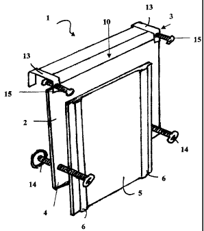
FIGURE 1 is a front perspective view of a support unit,
having a support member and a base pivotally connected to the
vertical support member, for a boat container storage unit
according to the present invention;

FIGURE 2 is a front perspective view of a boat container
storage unit according to the present invention comprising the
support unit of F'igure 1 and one embodiment of a container
adapted to slide onto the support unit;

FIGURE 3 is a front perspective view of the support unit
of FIGURE 1 with the base in its up position.

Further features of the invention will be described or will
become apparent in the course of the following detailed
description.


Detailed Description

Referring now to the drawings, FIGURE 1 illustrates a support
unit 1 for a boat. storage container unit according to the
present invention that is adapted to enable a user to perform

a variety of tasks thereon and when provided with a container
to store a variety of items therein. Although the support
unit 1 could take on a multitude of shapes and structures and


CA 02525377 2006-11-06
3

still accomplish its purpose, the embodiment as shown in
FIGURES 1-3 has a. vertical support member 2 which when mounted
on a boat, rests vertically on the inner side of the hull of
the boat and a support base 5 pivotally mounted to the

vertical support member 2.

The vertical support member 2 is attached to the boat by
mounting means, generally indicated at 3. The mounting means
illustrated in FIGURES 1-3 consist of a pair of downwardly

facing U-shaped gunwale clamps 13 with a threaded adjustment
screw 15 at a top edge 10 of vertical support member 2. The
downwardly facing U-shaped gunwale clamps 13 are sized and
shaped to fit over and hang on the gunwale of the hull of a
boat. The adjustment screws 15 are adapted to tighten onto the

gunwale to hold the vertical support member 2 in position. The
gunwale clamps 13 are sized and shaped to fit different sizes
of boats. In order to make sure the vertical support member 2
is in a vertical position and to keep the unit secured with
movement of the boat, a pair of hull clamps 14 in the form of

a pair of threaded adjustment screws are provided adjacent a
bottom edge 4 of vertical support member 2. While the
preferred embodiment illustrates gunwale clamps, other
suitable fastening means are useable and within the scope of
the present invention.

In order to mount. the boat storage container unit support 1 in
position on the side of the vessel, the hull clamps 14 will be
screwed through threaded holes in the vertical support member
2. The fisherman will twist the hull clamps 14 until the end
is securely positioned against the hull of the vessel.


CA 02525377 2006-11-06
4

The support base 5 in the embodiment illustrated is generally
flat and rectangular having one end pivotally connected to the
vertical support member 2. In the embodiment illustrated the
means to connect the base 5 to the vertical support member 2

consists of bracketing system 16. The bracketing system 16 has
a pair of vertical mounting members 7 and 45 angle brackets 8
where one end 18 of bracket 8 is mounted to the vertical
mounting member 7 and the other end of the bracket 19 is
mounted to the bottom surface of the base 5. The vertical

mounting members 7 are fastened to the vertical support member
2 by conventional fastening means, preferably by screws equi-
spaced along the vertical mounting members 7. The 45 angle
brackets 8 are attached to the bottom surface of base 5 using
screws. In order for the base 5 to go from its up to down

position, the bracketing system 10 operates on a hinge and
pivot system so that the support base 5 can rest flat with the
vertical support member 2 when in the down position (as shown
in FIGURE 1) and pivot to an up position as shown in FIGURE 3.
Brackets 8 must be adapted to lock in position so that the

base 5 is supported when in the up position. Brackets 8 must
also be adapted to un-lock so that the base 5 can pivot to the
down position whe.ri not in use. When in the down position the
base 5 folds away making travelling around the boat easier and
safer. When in the down position the support base 5 rests

parallel and flush with the vertical support member 2. This
maximizes the fisherman's usable space while operating their
vessel.

The boat storage container unit of the present invention
comprises a boat storage container support 1 and container
(box) 9 adapted to contain fishing tackle, tools etc. as best
shown in FIGURE 2. Different sizes and shapes for container 9


CA 02525377 2006-11-06

are within the scope of the present invention although a thin
design is preferred. The container 9 is adapted to slide on to
base 5 utilizing inter-engaging means on the container and
base, preferably a rib and groove connection. In the
5 embodiment illustrated, container 9 has a pair of grooves on
its bottom surface sized and shaped to allow it to quickly
slide into corresponding raised ribs 6 on the top surface of
base S. The combination rib and groove connection can be
reversed and permit the container 9 to slide onto and snap

into a stationary position on base 5 when in the up position.
Once immobile, the lid of the universal container 9 can be
opened and closed easily and allow the fisherman greater
accessibility while on board the vessel. The lid of the
container can be secured so that when the base is moved to the

closed position and container 9 is still on the base 5 it
won't fly open. Where the container 9 is attached to the base
5 in the down posi.tion, this keeps the container or box off
the floor of the boat and interfering with movement around the
boat or creating a safety hazard.


The boat storage container unit of the present invention maybe
fabricated from any suitable materials, most preferably ones
that are water resistant, light weight and durable, such as
treated wood, metal or, most preferably plastic. For ease of

cleaning and durability, it is most preferable that the boat
storage container unit be formed of highly durable plastic or
plastic polymer.

Although various preferred embodiments of the present

invention have been described herein in detail, it will be
appreciated by those skilled in the art, that variations may


CA 02525377 2007-10-24

6
be made thereto without departing from the spirit of the
invention.

6

Representative Drawing
A single figure which represents the drawing illustrating the invention.
Administrative Status

For a clearer understanding of the status of the application/patent presented on this page, the site Disclaimer , as well as the definitions for Patent , Administrative Status , Maintenance Fee  and Payment History  should be consulted.

Administrative Status

Title Date
Forecasted Issue Date 2008-07-29
(22) Filed 2005-11-04
Examination Requested 2007-04-12
(41) Open to Public Inspection 2007-05-04
(45) Issued 2008-07-29
Deemed Expired 2013-11-05

Abandonment History

There is no abandonment history.

Payment History

Fee Type Anniversary Year Due Date Amount Paid Paid Date
Application Fee $200.00 2005-11-04
Advance an application for a patent out of its routine order $500.00 2007-04-12
Request for Examination $400.00 2007-04-12
Maintenance Fee - Application - New Act 2 2007-11-05 $50.00 2007-10-29
Final Fee $150.00 2008-02-26
Section 8 Correction $200.00 2008-04-11
Maintenance Fee - Patent - New Act 3 2008-11-04 $50.00 2008-10-01
Maintenance Fee - Patent - New Act 4 2009-11-04 $50.00 2009-10-20
Maintenance Fee - Patent - New Act 5 2010-11-04 $100.00 2010-11-04
Maintenance Fee - Patent - New Act 6 2011-11-04 $300.00 2012-08-31
Owners on Record

Note: Records showing the ownership history in alphabetical order.

Current Owners on Record
HATTON, GRANT
Past Owners on Record
None
Past Owners that do not appear in the "Owners on Record" listing will appear in other documentation within the application.
Documents

To view selected files, please enter reCAPTCHA code :


To view images, click a link in the Document Description column. To download the documents, select one or more checkboxes in the first column and then click the "Download Selected in PDF format (Zip Archive)" or the "Download Selected as Single PDF" button.

List of published and non-published patent-specific documents on the CPD .

If you have any difficulty accessing content, you can call the Client Service Centre at 1-866-997-1936 or send them an e-mail at CIPO Client Service Centre.


Document
Description 
Date
(yyyy-mm-dd) 
Number of pages   Size of Image (KB) 
Description 2005-11-04 5 122
Claims 2005-11-04 3 86
Drawings 2005-11-04 3 89
Abstract 2006-11-06 1 22
Description 2006-11-06 6 206
Claims 2006-11-06 2 64
Drawings 2006-11-06 3 43
Representative Drawing 2007-04-27 1 8
Cover Page 2007-04-27 1 37
Description 2007-10-24 6 205
Claims 2007-10-24 2 63
Cover Page 2008-05-20 2 85
Claims 2008-02-26 2 65
Representative Drawing 2008-07-18 1 9
Cover Page 2008-07-18 2 42
Assignment 2005-11-04 3 84
Correspondence 2005-12-13 1 12
Correspondence 2008-02-26 3 94
Correspondence 2006-11-06 2 66
Prosecution-Amendment 2006-11-06 12 357
Prosecution-Amendment 2007-04-12 2 78
Prosecution-Amendment 2007-04-23 1 11
Prosecution-Amendment 2007-05-31 2 61
Prosecution-Amendment 2007-10-24 5 122
Correspondence 2007-10-29 1 22
Fees 2007-10-29 1 28
Correspondence 2008-04-04 1 14
Prosecution-Amendment 2008-04-11 1 26
Prosecution-Amendment 2008-05-20 2 57
Fees 2008-10-01 2 43
Correspondence 2008-10-01 2 44
Fees 2008-10-01 2 42
Fees 2009-10-20 1 25
Fees 2010-11-04 1 27
Fees 2012-08-31 1 207