Note: Descriptions are shown in the official language in which they were submitted.
CA 02525433 2005-11-10
WO 2004/100803 PCT/US2004/014782
A SYSTEM FOR IMPROVING CARDIAC FUNCTION
BACKGROUND OF THE IN!/ENTION
~ ). Field of the Invention
[000] Embodiments of this invention relate to a method and device for
improving
cardiac function.
2). Discussion of Related Art
[0002] Congestive heart failure annually leads to millions of hospital visits
internationally. Congestive heart failure is the description given to a myriad
of
symptoms that can be the result of the heart's inability to meet the body's
demand
for blood flow. In certain pathological conditions, the ventricles of the
heart become
ineffective in pumping the blood, causing a back-up of pressure in the
vascular
system behind the ventricle.
[0003] The reduced effectiveness of the heart is usually due an enlargement of
the
heart. A myocardial ischemia may, for example, cause a portion of a myocardium
of
the heart to lose its ability to contract. Prolonged ischaemia can lead to
infarction of
a portion of the myocardium (heart muscle) wherein the heart muscle dies and
becomes scar tissue. Once this tissue dies it no longer functions as a muscle
and
cannot contribute to the pumping action of the heart. When the heart tissue is
no
longer pumping effectively, that portion of the myocardium is said to be
hypokinetic,
meaning that it is less contractile than the uncompromised myocardial tissue.
As
this situation worsens, the local area of compromised myocardium may in fact
bulge
out as the heart contracts, further decreasing the heart's ability to move
blood
forward. When local wall motion moves in this way, it is said to be
dyskinetic, or
akinetic. The dyskinetic portion of the myocardium may stretch and eventually
form
CA 02525433 2005-11-10
WO 2004/100803 PCT/US2004/014782
an aneurysmic bulge. Certain diseases may cause a global dilated myopathy,
i.e., a
general enlargement of the heart when this situation continues for an extended
period of time.
[0004] As the heart begins to fail, distilling pressures increase, which
stretches the
ventricular chamber prior to contracfiion and greafily increases the pressure
in the
heart. In response, the hearfi tissue reforms to accommodate the chronically
increased filling pressures, furfiher increasing the work that the now
comprised
myocardium must perform.
[0005] This vicious cycle of cardiac failure results in the symptoms of
congestive
heart failure, such as shortness of breath on exertion, edema in the
periphery,
nocturnal dypsnia (a characteristic shortness of breath that occurs at night
after
going to bed), waking, and fatigue, to name a few. The enlargements increase
stress on the myocardium. The stress increase requires a larger amount of
oxygen
supply, which can result in exhaustion of the myocardium leading to reduced
cardiac
output of the heart.
SUMMARY OF THE INVENTION
[0007] The invention provides an apparatus for improving cardiac function
comprising at least one external actuator, an elongate manipulator connected
to the
external actuator, a manipulator-side engagement component on a distal end of
the
elongate manipulator, a collapsible and expandable frame, a frame-side
engagement
component releasably engageable with the manipulator side-engagement
component so that the external actuator can steer the frame when collapsed
into a
ventricle of a heart whereafter the frame is expanded, and at least one anchor
connected to the frame, movement of the external actuator allowing for (t)
insertion
of the anchor and (ii) a myocardium ventricle, (iii) subsequent withdrawal of
the
CA 02525433 2005-11-10
WO 2004/100803 PCT/US2004/014782
anchor of the myocardium, (iv) subsequent reinsertion of the anchor into the
myocardium, said insertion securing the frame to the myocardium in a selected
position, and (v) subsequent disengagement of the manipulator-side engagement
component from the frame-side engagemenfi component, said disengagement for
releasing the frame from the elongate manipulator.
[0008] The frame may have a small cross-dimension when collapsed suitable for
being inserted into fihe ventricle of the heart through a tubular passage in a
large
cross-dimension when expanded in the ventricle.
[0009] The frame may comprise plurality of segments extending from a central
portion of the frame.
[0010] The frame may be made of nickel titanium or stainless steel.
[0011] The apparatus may further comprise a membrane stretched between the
segments, the membrane dividing the ventricle into at least two volumes. The
membrane may be made of ePTFE. The membrane may be a mesh.
[0012] The segments may further comprise first and second portions connected
at ends thereof such that the second portions are at an angle to the first
portions.
[0013] The frame may have proximal and distal sections. The frame may have a
diameter of between 10 mm and 100 mm when expanded.
[0014] The apparatus may further comprise at least one active anchor and at
least one passive anchor. Said insertion of the passive anchor may be in a
first
direction and said withdrawal of the passive anchor may be in a second
direction, the
second direction being substantially 180 degrees from the first direction.
[0015] The apparatus may further comprise a first passive anchor extending in
the first direction and a second passive anchor extending in a third
direction. The
active and passive anchors may have sharp ends that penetrate the myocardium.
3
CA 02525433 2005-11-10
WO 2004/100803 PCT/US2004/014782
[0016] The apparatus may further comprise a tubular passage with a distal end
suitable to be inserted into the ventricle.
[001'7] The elongate manipulator may further comprise a frame member with
proximal and disfial ends and an anchor member with proximal and distal ends,
the
frame and anchor members being moveable through the tubular passage.
[001] The manipulator side-engagement component may further comprise a
frame formation on the distal end of the frame member and an anchoring
formation
on the distal end of the anchor member.
[0019] The apparatus may further comprise an external frame actuator connected
to the proximal end of the frame member and an external anchor actuator
connected
to the proximal end of the anchor member.
[0020] When the distal end of the elongate manipulator is in the selected
position,
a first movement of the external anchor actuator may cause the active anchor
to be
inserted into the myocardium to secure the frame to the myocardium and a
second
movement of the external anchor actuator may cause the active anchor to
withdraw
from the myocardium, said withdrawal releasing the frame from the myocardium.
[0021] A first movement of the external frame actuator may cause the frame
formation to engage the frame-side engagement component, said engagement
securing the frame to the distal end of the elongate manipulator and a second
movement of the external frame actuator may cause the frame formation to
disengage the frame-side engagement component, said disengagement releasing
the frame from the elongate manipulator.
[0022] The frame may be shaped such that entry of the proximal section of the
frame into the tubular passage causes the frame to partially collapse such
that the
passive anchor withdraws from the myocardium in the second direction and entry
of
CA 02525433 2005-11-10
WO 2004/100803 PCT/US2004/014782
the distal section of the frame into the tubular passage causes the frame to
collapse
to the small cross-section so that the distal end of the elongate manipulator
and the
frame can be removed from the heart.
[0023] The elongate manipulator and the frame may be insertable into the heart
simultaneously and the frame may be shaped such that exposure of the distal
section of the frame from the distal end of the tubular passage allows the
frame to
partially expand and exposure of the proximal section of the frame from the
distal
end of the tubular passage allows the frame to expand to a large cross-
section, said
expansion causing the passive anchors to penetrate the myocardium to secure
the
frame to the myocardium.
[0024] The invention also provides an apparatus for improving cardiac function
comprising a frame which includes a plurality of central segments surrounding
a
central axis, the central segments having first and second ends, the first
ends being
pivotally connected to one another, and a plurality of outer segments having
first and
second ends, the first ends being pivotally secured to the second ends of the
central
segments, a membrane secured to the frame such that movement of the second
ends of the central segments away from the central axis causes the membrane to
unfold, the unfolding of the membrane causing the outer segments to pivot
relative
to the respective central segments away from the central axis and movement of
the
second ends of the central segments toward the central axis causes the
membrane
to fold, the folding of the membrane causing the outer segments to pivot
relative to
their respective central segments toward the central axis, and an anchor
connected
to the frame, the anchor being insertable into a myocardium of a heart fio
secure the
cardiac device to the myocardium in a ventricle of the heart.
[0025] The frame may include at least three central segments and at least
three
CA 02525433 2005-11-10
WO 2004/100803 PCT/US2004/014782
outer segments.
[0026] The membrane may be stretched between the central and the outer
segments.
[002] The anchor may be secured directly to fihe frame.
[0023] The invention further provides an apparafius for improving cardiac
function
comprising a frame, a membrane, having an inner surface, secured to the frame,
the
membrane and the frame jointly forming a cardiac device being moveable between
a collapsed and an expanded state, in a collapsed state at least a portion of
the inner
surface of the membrane facing a vertical axis of the cardiac device and the
cardiac
device being insertable into a ventricle of a heart, in the expanded sfiate
the portion
of the inner surface of the membrane facing away from the vertical axis and
being in
contact with a myocardium and the cardiac device being in a selected position
in the
ventricle, and an anchor connected to the cardiac device, the anchor being
insertable into the myocardium of the heart to secure the cardiac device to
the
myocardium in the selected position in the ventricle.
[0029] The cardiac device may collapse toward the vertical axis and expand
away
from the vertical axis.
[0030] The membrane may fold towards the vertical axis when the cardiac device
collapses and may unfold away from the vertical axis when the cardiac device
expands.
[0031] The frame may be at least one of nickel titanium and stainless steel.
[0032] The membrane may be made of ePTFE.
[0033] The anchor may have a sharp end.
[0034] The invention further provides an apparatus for improving cardiac
function
comprising a frame being expandable in a selected position to a pre-set shape
in a
CA 02525433 2005-11-10
WO 2004/100803 PCT/US2004/014782
ventricle of a heart, a formation on the frame, and an anchoring device having
an
anchor, the anchoring device being engaged with and rotatable relative the
formation
to rotate the anchor relative to the frame, said rotation causing the anchor
to be
inserted into a myocardium of the heart, said insertion securing the frame in
the
selected position in the ventricle.
[0035] The anchoring device may engage the formation such that a first
rotation of the anchoring devise causes fibs anchor to move away from the
frame and
a second rotation of the anchoring device causes the anchor to move toward the
frame.
[0036] The formation may be a pin, and the anchor may be a screw.
[0037] The invention further provides an apparatus for improving cardiac
function
comprising at least a primary expandable frame being in a selected position in
a
ventricle of a heart when expanded, an anchor connected to the frame, the
anchor
being insertable into a myocardium of the heart to secure the primary frame
within
the ventricle, a frame-side engagement component connected to the primary
frame,
a membrane, and a membrane-side engagement component being engageable with
the frame-side engagement component, said engagement securing the membrane to
the frame.
[003] The apparatus may further comprise a secondary expandable frame being
in a selected position in the ventricle of the heart when expanded, the
secondary
frame being secured to the membrane and connected to the membrane-side
engagement component thereby interconnecting the membrane to the membrane-
side engagement component.
[0039] The anchor may be connected to the at least one frame.
[0040] The frame-side engagement component may be connected to the primary
7
CA 02525433 2005-11-10
WO 2004/100803 PCT/US2004/014782
frame at a central portion of the primary frame.
[0041] The membrane-side engagement component may be connected to the
secondary frame at a central portion of the secondary frame.
[004] The apparatus may further comprise an active anchor being connected to
the frame-side engagement component such that a first movement of the frame-
side
engagement component causes the active anchor to enter the myocardium and a
second movement of the frame-side engagement component causes the active
anchor to withdraw from the myocardium.
[0043] The apparatus may further comprise a passive anchor being connected to
at least one of the frames such that the passive anchor enters the myocardium
when
the frame expands.
[0044] The invention further provides an apparatus for improving cardiac
function
comprising a flexible liner, a membrane secured to the liner, the membrane and
the
liner jointly forming a cardiac device being moveable between a collapsed and
an
expanded state, in the collapsed state the cardiac device being insertable
into a
ventricle of a heart. In the expanded state the cardiac device being in a
selected
position in the ventricle, the liner covering a wall in the ventricle and the
membrane
separating the ventricle into two volumes, and an anchor connected to the
cardiac
device, the anchor being insertable into a myocardium of the heart to secure
the
cardiac device to the myocardium in the selected position in the ventricle.
[0045] The flexible liner may comprise a plurality of lengths of strands being
connected at endpoints thereof.
[0046] The apparatus may further comprise a frame secured to the cardiac
device
and connected to the anchor thereby interconnecting the cardiac device and the
anchor.
CA 02525433 2005-11-10
WO 2004/100803 PCT/US2004/014782
[0047] The apparatus may further comprise a frame-side engagement component
being connected to the cardiac device and an active anchor being connected to
the
frame-side engagement component such that a first movement of the frame-side
engagement component causes the active anchor to enter the myocardium and a
second movement of the frame-side engagement component causes the active
anchor to withdraw from the myocardium.
[004] The apparatus may further comprise a passive anchor being connected to
the cardiac device such that the passive anchor enters the myocardium when the
cardiac device expands.
[0049] The invention further provides an apparatus for improving cardiac
function
comprising an expandable frame being in a selected position in a ventricle of
the
heart and having an outer edge when expanded, the outer edge defining a non-
planar cross-section of an inner wall of a ventricle and an anchor connected
to the
frame, the anchor being insertable into the myocardium of the heart to secure
the
frame to the myocardium in the selected position in the ventricle.
[0050] The apparatus may further comprise a membrane being secured to a
frame, the membrane separating the ventricle into two volumes.
[0051] The frame may have a vertical axis and the outer edge may have a
diameter, the diameter intersecting the vertical axis at an angle other than
90
degrees.
[0052] The invention further provides an apparatus for improving cardiac
function
comprising an anchor being insertable into a myocardium of a heart to secure
the
anchor to the myocardium within a ventricle of the heart, an anchor-side
engagement
component being secured to the anchor, an expandable frame being in a selected
position in the ventricle when expanded, and a frame-side engagement component
CA 02525433 2005-11-10
WO 2004/100803 PCT/US2004/014782
being secured to the firame, the frame-side engagement component being
engageable with the anchor-side engagement component, said engagement
securing the frame to the anchor in the selected position in the ventricle.
[0053] The apparatus may further comprise a membrane being secured to the
frame.
[0054] A first movement of the anchor-side engagement component may cause
the anchor to enter a myocardium and a second movement of the anchor-side
engagement component may cause the anchor to withdraw from the myocardium.
[0055] A first movement of the frame-side engagement component may cause
the frame-side engagement component to engage the anchor-side engagement
component and a second movement of the frame-side engagement component may
cause the frame-side engagement component to disengage the anchor-side
engagement component.
[0056] Said engagement may release the frame from the anchor.
[0057] The invention further provides an apparatus for improving cardiac
function
comprising a flexible body, a membrane connected to the flexible body, the
membrane and flexible body jointly forming a cardiac device being movable
between
a collapsed and an expanded state, in the collapsed state the cardiac device
being
insertable into a ventricle of the heart, in the expanded state the cardiac
device being
in a selected position in the ventricle, and an anchor connected to the
cardiac
device, the anchor being insertable into the myocardium of the heart to secure
the
cardiac device to the myocardium in fihe selected position of the ventricle.
[0058] The apparatus may further comprise a frame having a distal end, the
membrane may be secured to the frame, and the body may have proximal and
distal
ends, the proximal end of the body being secured to the distal end of the
frame, and
to
CA 02525433 2005-11-10
WO 2004/100803 PCT/US2004/014782
the distal end of the body being connected to the anchor.
[0059] The body may be cylindrical with a diameter of between 0.5 mm and 6 mm
and a height of between 1 mm and 100 mm.
[0060] The cardiac device may have a vertical axis.
[0061] The body may have a proximal opening at the proximal end, a distal
opening at the distal end, and a passageway therethrough connecting the
proximal
and distal openings.
[0062] The body may be able to bend between 0 and 120 degrees from the
vertical axis.
[0063] The invention further provides a device for improving cardiac function
comprising a collapsible and expandable frame having first and second
portions, the
frame being insertable into a ventricle of a heart when collapsed, when
expanded the
frame being in a selected position in the ventricle and the second portion of
the
frame covering a wall in the ventricle, a membrane secured to the frame such
that
the membrane divides the ventricle into at least two volumes when the frame is
expanded, the frame and the membrane jointly forming a cardiac device, and an
anchor connected to the cardiac device, the anchor being insertable into a
myocardium of the heart to secure the cardiac device in the selected position
in the
ventricle.
[0064] The frame may further comprise a plurality of segments, each segment
having an inner and outer portion being connected at ends thereof, the outer
portions
being at an angle to the inner portions.
[0065] The membrane may be secured to the inner and outer portions of the
segments.
[0066] The device may further comprise a plurality of anchors being connected
to
11
CA 02525433 2005-11-10
WO 2004/100803 PCT/US2004/014782
at least one segment such that when the frame expands the anchors enter the
myocardium in a first direction, and when the frame collapses the anchors
withdraw
from fibs myocardium in a second direction approximately 1 ~0 degrees from the
first
direction.
[006 Some of the anchors may extend in a third direction.
[006] The invention further provides a system for improving cardiac function
comprising a collapsible and expandable frame, when collapsed the frame being
insertable into a selected position in a ventricle of the heart through an
opening in
the heart having a small cross-dimension, when expanded in the selected
position,
the frame having a large cross-dimension, and an anchor connected to the
frame,
being insertable into a myocardium of the heart to secure the frame to the
myocardium in the selected position.
[0069] The opening may be an incision in the myocardium.
[000] The anchor may further comprise a plurality of strands woven through the
myocardium such that the opening is closed.
[0071] The invention further provides a system for improving cardiac function
comprising an external actuator, an elongate manipulator having a tube
suitable to
be inserted into a ventricle of a heart to a selected position and a
deployment
member positioned therein slidable between a first and second position, the
deploymenfi member having proximal and distal ends, the distal end being
within the
tube when the deployment member is in the first position and out of the tube
when
the deployment member is in the second position, the deployment member being
connected to the external actuator at the proximal end thereof, a deployment-
side
engagement component on the distal end of the deployment member, a frame-side
engagement component being engageable with the deployment-side engagement
12
CA 02525433 2005-11-10
WO 2004/100803 PCT/US2004/014782
component, said engagement securing the deployment-side engagement component
to the frame-side engagement component such that a movement of the external
actuator causes the engagement components to disengage, said disengagement
releasing the deployment-side engagement component from the frame-side
engagement component, a frame being connected to the frame-side engagement
component, the frame being moveable between a collapsed and an expanded state,
the frame being connected to the deployment member in the collapsed state with
a
small cross-dimension when the deployment member is in the first position and
the
frame is within the tube, the frame being shaped such that when the deployment
member is moved to the second position and the frame exits the tube, the frame
expands to the expanded state with a large cross-dimension and when the
deployment member is moved back to the first position, the frame collapses to
the
collapsed state as the frame enters the tube, and an anchor connected to the
frame
being insertable into a myocardium of the heart to secure the frame to the
myocardium of the heart, such that the deployment mechanism can be removed
from the heart, the anchor entering the myocardium in a first direction when
the
frame expands and withdrawing from the myocardium in a second direction when
the
frame collapses, said withdrawal releasing the frame from the myocardium.
[0072] The external manipulator may further comprise an anchor deployment
knob and a detachment knob.
[003] The deployment member may further comprise an anchor shaft having
proximal and distal ends and a detachment shaft having proximal and distal
ends,
the proximal end of the anchor shaft being connected to the anchor deployment
knob, the proximal end of the detachment shaft being connected to the
detachment
knob.
13
CA 02525433 2005-11-10
WO 2004/100803 PCT/US2004/014782
[0074] The deployment-side engagement component may further comprise a
deployment-side anchor formation connected to the distal end of the anchor
shaft
and a deployment-side detachment f~rmation connected to the disfial end of the
detachment shaft.
[005] The frame-side engagement component may further comprise a frame-
side anchor formation being connected to the anchor and a frame-side
detachment
formation on the frame, the frame-side anchor formation being engageable with
the
deployment-side anchor formation, the frame-side detachment formation being
engageable with the deployment-side detachment formation, a first movement of
the
detachment knob causing the deployment-side detachment formation to engage the
frame-side detachment formation, said engagement securing the frame to the
deployment member, a first movement of the anchor deployment knob causing the
anchor to enter the myocardium and a second movement of the anchor deployment
knob causing the anchor to withdraw from the myocardium, a second movement of
the detachment knob causing the deployment-side detachment formation to
disengage the frame-side detachment formation, said disengagement releasing
the
frame from the deployment member.
[0076] The anchor shaft and the detachment shaft may be coaxial.
[0077] The anchor shaft may be an inner torque shaft and the detachment shaft
may be an outer torque shaft.
BRIEF DESCRIPTI~N ~F THE DRAWINGS
[0006] The invention is further described by way of examples with reference to
the
accompanying drawings, wherein:
[0007] Figure 1 is an exploded side view of a system for improving cardiac
function, according to one embodiment of the invention, including a cardiac
device
14
CA 02525433 2005-11-10
WO 2004/100803 PCT/US2004/014782
and a deployment system, the deployment system including a deployment
mechanism and a catheter tube;
[0008] Figure 2 is a cross-sectional side view of a handle of the deployment
mechanism and a proximal end of a deployment member of the deployment
mechanism;
[0009] Figure 3A is cross-sectional side view of a distal end of the
deployment
member including a key and a detachment screw;
[0010] Figure 3B is a cross-sectional end view on 3B-3B in Figure 3A of the
deployment member;
[0011] Figure 3C is a cross-sectional end view on 3G-3G in Figure 3A of the
key;
[0012] Figure 4 is a perspective view of the cardiac device including a hub, a
frame, and a stem thereof;
[0013] Figure 5A is a side view of the cardiac device;
[0014] Figure 5B is a perspective view of the hub;
[0015] Figure 5C is a top plan view of the hub;
[0016] Figure 6 is a cross-sectional side view of the stem;
[0017] Figure 7A is a side view of the distal end of the deployment member
connected to the cardiac device;
[0018] Figure 7B is a cross-sectional view on 7B-7B in Figure 7A of the
cardiac
device;
[00'19] Figure 8 is a cross-sectional side view of the cardiac device with the
key
connected thereto;
[0020] Figure 9 is a side view of the system of Figure 1 with the components
integrated with and connected to one another;
[0021] Figure 10A is a view similar to Figure 9 with the cardiac device
partially
is
CA 02525433 2005-11-10
WO 2004/100803 PCT/US2004/014782
retracted into the catheter;
[0022] Figure 10B is a cross-sectional side view of a portion of Figure 10A;
[0023] Figure 11A is a side view of the system with the cardiac device further
retracted;
[0024] Figure 11B is a cross-sectional side view of a portion of Figure 11A;
[0025] Figure 12A is a side view of the system with the cardiac device fully
retracted;
[0026] Figure 12B is a cross-sectional side view of a portion of Figure 12A;
[0027] Figure 13A is a cross-sectional side view of a human heart with the
catheter
inserted therein;
[0028] Figures 13B-13K are cross-sectional side views of the human heart
illustrating installation (Figures 13B -13E), removal (Figures 13E -13H), and
subsequent final installation (Figures 131-13K) of the cardiac device;
[0029] Figure 14A is a perspective view of a cardiac device according to
another
embodiment of the invention;
(0030] Figure 14B is a cross-sectional side view of the human heart with the
cardiac device of Figure 14A installed;
[0031] Figure 15A is a perspective view of a cardiac device according to a
further
embodiment on the invention;
[0032] Figure 15B is a cross-sectional top plan view of the cardiac device on
15B-
15B in Figure 15A;
[0033] Figure 15C is a cross-sectional side view of the human heart with the
cardiac device of Figure 15A installed;
[0034] Figure 16A is a perspective view of a cardiac device according to a
further
embodiment of the invention;
16
CA 02525433 2005-11-10
WO 2004/100803 PCT/US2004/014782
[0035] Figure 16B is a cross-sectional side view of the cardiac device of
Figure
16A;
[0036] Figure 16C is a cross-sectional side view of the human heart with the
cardiac device of Figure 16A installed;
[003'F] Figure 17A is a perspective view of a cardiac device according to a
further
embodiment of the invention;
(0038] Figure 17B is a cross-sectional side view of the human heart with the
cardiac device of Figure 17A installed;
[0039] Figure 18A is a perspective view of a cardiac device according to a
further
embodiment of the invention;
[0040] Figure 18B is a cross-sectional side view of the human heart with the
cardiac device of Figure 18A installed;
[0041] Figure 19A is a perspective view of a cardiac device according to a
further
embodiment of the invention;
[0042] Figure 19B is a cross-sectional side view of the human heart while the
cardiac device of Figure 19A is being installed;
[0043] Figure 19C is a cross-sectional side view of the human heart while the
cardiac device of Figure 19A is being installed;
[0044] Figure 19D is a cross-sectional side view of a human heart with the
cardiac
device of Figurer 19A installed;
[0045] Figure 20A is a perspective view of a frame of a cardiac device
according to
another embodiment of the invention;
[0046] Figure 20B is a perspective view of a stem of the cardiac device of
Figure
20A;
[0047] Figure 20C is a cross-sectional side view of the cardiac device of
Figure
17
CA 02525433 2005-11-10
WO 2004/100803 PCT/US2004/014782
20A and Figure 20B with the stem attached to the frame;
[0048] Figure 20D is a cross-sectional side view of a distal end of a
deployment
member of a deployment mechanism according to another embodiment of the
invention;
[004.x] Figure 20E is a cross-sectional side view of the distal end of the
deployment member of a deployment mechanism of Figure 20D; and
[0050] Figures 20F - 201 are cross sectional side views of a human heart
illustrating installation of the cardiac device of Figure 20A and Figure 208.
DETAILED DESCRIPTION OF THE INVENTION
(0051] Figure 1 illustrates a system 30 for improving cardiac function
according to
one embodiment of the invention. The system 30 includes a deployment system 32
and a cardiac device 34. The deployment system 32 includes a deployment
mechanism 36 and a catheter tube 38.
(0052] The catheter tube 38 is cylindrical with a length 40 of 110 cm and a
diameter 42 of 5 mm. The catheter tube 38 has a circular cross-section and is
made
of a soft, flexible material.
[0053] The deployment mechanism 36 includes a handle 44 and a deployment
member 46. The handle 44 has a proximal end 48 and a distal end 50. The
deployment member 46 has a proximal end 52 and a distal end 54. The proximal
end 52 of the deployment member 46 is secured to the distal end 50 of the
handle
44.
[0054] Figures 2, 3A, 38, and 3C illustrate the deployment mechanism 36 in
more
detail. Figure 2 illustrates the handle 44 while Figures 3A, 3B, and 3C
illustrate
components at the distal end 54 of the deployment member 46. The components of
the deployment mechanism 36 are primarily circular with center lines on a
common
is
CA 02525433 2005-11-10
WO 2004/100803 PCT/US2004/014782
aXIS.
[0055] The handle 44 is made of molded plastic and includes a main body 56, an
anchor knob 58, an end piece 60, a proximal rotating hemostatic valve 62, a
fluid line
64, a distal rotating hemostatic valve 55, and a detachment knob 68. The main
body
56 is cylindrical with a length 70 of 80 mm and a diameter 72 of 25 mm. The
main
body 56 has a proximal 74 and a distal 76 opening at the respective ends
thereof
and a passageway 78 therethrough connecting the openings with an inner
diameter
80 of 4 mm.
[0056] The proximal rotating hemostatic valve 62 is a cylindrical body with a
passageway 82 therethrough having an inner diameter 84 of 4 mm, a locking hypo
tube 86 within the passageway, a tapered outer end 88, and a raised formation
90 at
a central portion thereof. The proximal rotating hemostatic valve 62 is
rotationally
secured to the proximal opening 74 of the handle 44. The locking hypo tube 86
is a
cylindrical body secured within the passageway 82 of the proximal rotating
hemostatic valve 62.
[0057] The end piece 60 is a cylindrical body with a passageway 92
therethrough
connecting a proximal 94 and distal 96 opening at respective ends and having
an
inner diameter 98 of 5 mm. Raised formations 100 stand proud from respective
central and outer portions of the end piece. A cylindrical end piece pin 102
is
connected to an inner surface and extends across the inner diameter 98 of the
passageway 92. The end piece pin 102 is made of stainless steel and has a
length
of 5 mm and a diameter of 2 mm. The distal opening 96 of the end piece 60
mates
with the tapered outer end 88 of the proximal rotating hemostatic valve 62.
[0058] The anchor knob 58 is a cap-shaped body with a length 104 of 20 mm and
an outer diameter 106 of 10 mm. The anchor knob 58 has a small opening 108 at
a
19
CA 02525433 2005-11-10
WO 2004/100803 PCT/US2004/014782
proximal end 110 with a diameter 112 of 4 mm and a large opening 114 at a
distal
end 116 with a diameter 118 of 6 mm. The anchor knob 58 fits over and is
secured
to both the end piece 60 and the proximal rotating hemostatic valve 62.
[0059] The fluid line 64 enters the handle 44 through the small opening 108 of
the
anchor knob 58 and is secured fio the proximal opening 94 of the end piece 60.
The
fluid line 64 has an outer diameter 120 of 5 mm.
[0060] The distal rotating hemostatic valve 66 is a cylindrical body with a
passageway 122 therethrough having a proximal inner diameter 124 of 4 mm at a
proximal end 126 thereof and a distal inner diameter 128 of 5 mm at a distal
end 130
thereof. The distal end 130 is tapered, and a raised formation 132 lies at a
central
portion thereof. The distal rotating hemostatic valve 66 is rotationally
secured to the
distal opening 76 of the main body 56.
[0061] The detachment knob 68 is a cap-shaped body with a length 134 of 20 mm
and an outer diameter 136 of 20 mm. The detachment knob 68 has a large opening
138 at a proximal end 140 with a diameter 142 of 8 mm and a small opening 144
at a
distal end 146 with a diameter 148 of 5 mm. The detachment knob 68 fits over
and
is secured to the distal rotating hemostatic valve 66.
[0062] Referring to Figures 3A - 3C, the deployment member 46 includes an
inner
torque shaft 150 and an outer torque shaft 152. The inner torque shaft has a
diameter 154 of 2 mm and is made of surgical stainless steel. The outer torque
shaft
is a hollow, cylindrical body with an inner diameter 156 of 3 mm and an outer
diameter 158 of 5 mm. The outer torque shaft 152 is a polymer.
[0063] Referring again to Figure 2, the inner torque shaft 150 passes through
the
detachment knob 68, through the distal rotating hemostatic valve 66, into and
out of
the passageway 78 of the main body 56, through the proximal rotating
hemostatic
CA 02525433 2005-11-10
WO 2004/100803 PCT/US2004/014782
valve 62, and into the end piece 60. The proximal end of the inner torque
shaft 150
is wrapped around the end piece pin 102, reenters the proximal rotating
hemostatic
valve 62, and is attached to the locking hypo tube 86 within the proximal
rotating
hemostatic valve 62.
[00~4~] The oufier fiorque shaft 152 is coaxial with and surrounds the inner
torque
shaft 150. A proximal end 160 of fihe outer torque shaft 152 passes into the
distal
hemosfiatic valve 66 and is secured thereto.
[0065] The distal end 54 of the deployment member 46 includes a key 162, a
detachment screw 164, and a securing mechanism 166. A distal end 168 of the
inner torque shaft 150 extends out of a distal end 170 of the outer torque
shaft 152,
and the key 162 is attached thereto. The key 162 is rectangular with a length
171 of
7 mm and a height 172 of 3 mm. The key 162 has a semi-circular cross section
with
a radius 174 of 1.5 mm. The detachment screw 164 is attached to the distal end
170
of the outer torque shaft 152, extends to a length 176 of 7 mm, and has a
diameter
178 of 5 mm.
[0066] The securing mechanism 166 includes an inner component 180 and an
outer component 182. The inner component 180 is a raised cylindrical portion
coaxial with and on the inner torque shaft 150. The inner component 180 stands
proud of the inner toque shaft 150 by 0.5 mm. The outer component 182 is a
hollow,
cylindrical body secured to an inner surFace of the outer torque shaft 152 and
has
proximal and distal openings with diameters of 2.25 mm so that the inner toque
shaft
150 cannot move axially relative to the outer torque shaft 152.
[0067] Figures 4, 5A - 5C, and 6 illustrate the cardiac device 34 in more
detail.
The cardiac device 34 includes a frame 184 and a stem 186, or flexible body,
and
has a vertical axis 188.
21
CA 02525433 2005-11-10
WO 2004/100803 PCT/US2004/014782
[0068] The frame 184 includes a frame hub 190, a plurality of main segments
792,
and a membrane 194. The hub 190 is a ring-shaped body with an outer surface
196
with a diameter 198 of 5 mm, an inner surfiace 200 with a diameter 202 of 4
mm, a
thickness 204 of 3 mm, and a pin 206 extending off center across the inner
surfiace
200 creating a smaller and a larger gap. The pin 206 has a length of 3.5 mm
and a
diameter of 1 mm and is located in a plane 208. The frame 184 has a diameter
209
of approximately 25 mm, however, other embodiments may have diameters of
between 10 mm and 100 mm. The entire hub 190 is made of nickel titanium.
[0069] The main segments 192 include first portions, or central segments, 210,
second portions, or outer segments, 212, and passive anchors 214. The first
portions 210 are connected to the hub 190 at a central portion of the outer
surface
196 and extend radially from the hub 190 at an angle away from the plane 208
of the
pin 206 to a length 216 of 8 mm. The second portions 212 of the segments 192
are
connected to ends of the first portions 210 and further extend radially from
the hub
190 but at an angle towards the plane 208. The second portions 212 each have a
length 218 of 5 mm. The passive anchors 214 are formed at an end of each of
the
second portions 212. The passive anchors 214 have sharp ends that point
slightly
radiaily from the hub 190. The segments 192 are made from nickel titanium,
which
after a prescribed thermal process, allows for the segments 192 to hold their
shape
as illustrated, for example, in Figure 4. The entire frame 184, or just
portions of the
frame 184, may also be made of stainless steel.
(0070] The membrane 194 is stretched over the first 210 and second 212
portions
of the segments 192 fio give the frame 184 a disk like shape. The membrane 194
is
made of expanded Poly Tetra Fuoro Ethylene (ePTFE) and has a thickness of 0.08
mm. Other embodiments may use a mesh membrane.
22
CA 02525433 2005-11-10
WO 2004/100803 PCT/US2004/014782
[0071] Figure 6 illustrates the stem 186 unattached to the frame 184. The stem
186 is a hollow, cylindrical body with a passageway 220 therethough connecting
a
proximal 222 and a distal 224 opening. The stem 186 has a height 226 of 9 mm,
an
outer diameter 228 of 5 mm, and an inner diameter 230 of 4 mm. The stem 186
includes a first hub 232 and a second hub 234, both similar to the hub 190 on
the
frame 184. The second hub 234 is secured within the passageway 220 near the
distal opening 224 of the stem 186. The first hub 232 is loose within the stem
186 so
that it may move, and has an active anchor 236, in the shape of a screw,
attached.
The active anchor 236 spirals from the first hub 232 to engage with the pin on
the
second hub 234. The active anchor 236 has a diameter 238 of 3.5 mm and a
length
240 of 7 mm.
[0072] The stem 186 is made of Poly Tetra Fuoro Ethylene (PTFE) and is thus
expandable and flexible. Referring again to Figure 4, the stem 186 can be
compressed or stretched by 30% of its length and can be bent from the vertical
axis
188 of the device 34 by 120 degrees in any direction. The first hub 232,
second hub
234, and active anchor 236 are made of nickel titanium. In other embodiments,
the
hubs may be made of stainless steel.
[0073] Figures 7A, 7B, 8, and 9 illustrate the system 30 with the stem 186
connected to the cardiac device 34 and the cardiac device 34 connected to the
deployment mechanism 36. The stem 186 is fused to the frame hub 190 thus
securing the stem 186 to the device 34.
[0074] In use, the deployment member 46 is inserted through the catheter tube
38
so that the distal end 54 of the deployment member 46 exits the distal end of
the
tube 38. As shown is Figures 7A and 7B, fibs deployment member 46 connects t~
the cardiac device 34 such that the key 162 engages the hub 190 of the frame
184
23
CA 02525433 2005-11-10
WO 2004/100803 PCT/US2004/014782
by passing through the larger gap in the hub 190. As shown in Figure 8, the
key 162
passes through the hub 190 of the frame 184 to engage with the first hub 232
of the
stem 186, but does not reach the second hub 234. ~nce the key 162 is fully
inserted
into the stem 186, the detachment knob 68 is turned which rotates the outer
fiorque
shaft 152 and thus the detachment screw 164 because the detachment screw 164
is
attached to the outer torque shaft 152. The rotation thereof causes the
detachment
screw 164 to engage with the pin 206 of the frame hub 190, securing the
cardiac
device 34 to the deployment mechanism 36.
[0075] Rotation of the anchor knob 58 in a first direction causes the active
anchor
236 to be deployed from the distal opening 224 of the stem 186 because the
anchor
knob 58 is connected to the inner torque shaft 150 which, in turn, is
connected to the
key 162. Rotation of the key 162 causes the first hub 232 to rotate and
because the
active anchor 236 is connected to the first hub 232 and engaged with the pin
of the
second hub 234, the active anchor 236 "twists" out of the distal opening 224
of the
stem while the first hub 232 is pulled toward the distal opening 224. Rotation
of the
anchor knob 58 in a second direction causes the active anchor 236 to reenter
the
distal opening 224 of the stem 186.
[0076] As illustrated in Figures 10A and 10B, the distal end 54 of the
deployment
member 46 is then pulled into the distal end of the catheter tube 38. As a
proximal
section of the frame 184 enters the catheter tube 38, the first portions 210
of the
segments 192 begin to collapse towards the stem 186. The segments 192
collapse,
or fold, against a spring force that is created by the resilient nature of the
nickel
titanium material from which they are made. At the same time, the second
portions
212 fan out radially away from the hub 190.
[0077] As illustrated in Figures 11 A and 11 B, by the time a distal section
of the
24
CA 02525433 2005-11-10
WO 2004/100803 PCT/US2004/014782
frame 184 and the second portions 212 of the segments 192 begin to enter the
tube
38, the second portions 212 have been bent back to collapse towards the stem
186
similarly to the first portions 210.
[00'8, Figures 12A and 12~ illustrafie the system 30 with the cardiac device
34
completely contained within the catheter tube 38.
[0079] Figures 13A - 13J illustrate a human heart 242 while the cardiac device
34
is being deployed. The heart 242 contains a right ventricle 244 and a left
ventricle
246 with papillary muscles 248 and an akinetic portion 250 with an apex 252.
The
distal end of the catheter 38 has been inserted through the aorta and aortic
valve
into the left ventricle 246 to a selected position where the cardiac device 34
can be
deployed. The catheter tube 38 is then partially pulled off of the cardiac
device 34
exposing the stem 186.
[0080] The active anchor 236 is then deployed by rotating the anchor knob 58
in a
first direction. The active anchor 236 penetrates the myocardium of the heart
242 to
secure the cardiac device 34 in the selected position at the apex 252 of the
akinetic
portion 250 of the left ventricle 246.
[0081) The catheter 38 is then completely removed from the distal end 54 of
the
deployment member 46, exposing the cardiac device 34. As the cardiac device 34
expands, due to the resilient nature of the segments 192 and the pre-set shape
of
the frame 184, the passive anchors 214 on the segments 192 penetrate the
myocardium in a first direction. The membrane 194 seals a portion of the
ventricle
246 and separates the ventricle 246 into two volumes.
[0082] If the cardiac device 34 has not been properly positioned, or if it is
of the
wrong sire or shape for the particular heart, the device 34 may be
repositioned or
completely removed from the heart 242.
2s
CA 02525433 2005-11-10
WO 2004/100803 PCT/US2004/014782
[0083] Rotation of the anchor knob 58 in a second direction will cause the
active
anchor 236 to be removed from the apex 252 of the akinetic portion 250 of the
left
ventricle 246 thus releasing the cardiac device 34 from the heart 242. The
distal end
54 of the deployment member 46 may be retracted into the cafiheter 38 to once
again
fold the cardiac device 34 into the position shown in Figure 12E, from where
it can
again be deployed. The passive anchors 214 are removed from the myocardium in
a second direction which is approximately 180 degrees from the first direction
so that
minimal damage is done to the myocardium.
[0084] However, if the cardiac device 34 has been properly positioned and is
of the
proper size and shape, rotation of the detachment knob 68 in a second
direction will
cause the detachment screw 164 at the distal end 170 of the outer torque shaft
152
to disengage the pin 206 in the frame hub 190, thus releasing the deployment
member 46 from the cardiac device 34 fio allow removal of the deployment
member
46 from the heart 242. Figure 13K illustrates the heart 242 with the cardiac
device
34 installed and the deployment mechanism 36 removed from the heart 242.
[0085] One advantage of this system is that the shape of the frame 184 allows
the
device 34 to be retrieved as long as the deployment member 46 is still
connected to
the device 34. When the device 34 is retrieved, the passive anchors 214
withdraw
from the myocardium in a direction that is approximately 180 degrees from, or
opposite, the first direction to minimize the amount of damage done to the
myocardium. The device 34 also provides support for the akinetic region 250,
minimizes the bulging of the akinetic region 250, and reduces stress on the
working
parts of the myocardium. A further advantage is that the ePTFE membrane 194 is
biocompatible, has a non-thrombogenic surface, promotes healing, and
accelerates
endothelization.
26
CA 02525433 2005-11-10
WO 2004/100803 PCT/US2004/014782
(0086] Figure 14A illustrates a cardiac device 254 according to another
embodiment of the invention. The cardiac device includes a hub 256, a frame
258,
and a membrane 260. The hub 256 lies at a central portion of the frame 258 and
an
active anchor 262 is connected to the hub 256 and extends downwards therefrom.
The frame 258 includes a plurality of segments 264 which extend radially and
upwardly from the hub 256. A sharp passive anchor 266 lies at the end of each
of
fibs segments 264. The membrane 260 is stretched between the segments 264 to
form a cone-shaped body.
[0087] Figure 14B illustrates a human heart with the cardiac device 254 of
Figure
14A having been secured to an akinetic portion thereof.
(0088] Figure 15A and Figure 15B illustrate a cardiac device 268 according to
a
further embodiment of the invention. The cardiac device includes a hub 270, a
frame
272, and membrane 274. The hub 270 lies at a central portion of the frame 272
and
an active anchor 276 extends downwardly from the hub 270. The frame 272
includes a plurality of segments 278 which extend radially and upwardly from
the hub
270. The segments 278 are of different lengths such that an outer edge 280 of
the
cardiac device 268 is not planar. The device 268 has a vertical axis 282 which
intersects a diameter 284 across the outer edge 280 of the device 268 at an
angle
other than 90 degrees. A sharp passive anchor 286 lies at the end of each of
the
segments 278. The membrane 274 is stretched between the segments 278 to form
a cone-shaped body. Referring specifically to Figure 15B, a cross-section
perpendicular to the vertical axis 282 of the device 268 is circular.
[0089] Figure 15C illustrates a human heart with the cardiac device 268 of
Figure
15A having been secured to an akinetic portion thereof. The outer edge 280 of
the
cardiac device 268 defines a non-planar cross-section of an inner surface of
the left
27
CA 02525433 2005-11-10
WO 2004/100803 PCT/US2004/014782
ventricle.
[0090] A further advantage of this embodiment is that the device 268 can be
sized
and shaped for use on a wider variety of alcinetic portions in left
ventricles.
[009°1] Figure 16A and Figure 10B illustrate a cardiac device 288
according to a
further embodiment of the invention. The cardiac device 288 includes a first
hub
290, a first frame 292, a second hub 294, a second frame 296, a first membrane
298, and a second membrane 300. The first hub 290 is attached to a cenfiral
portion
of the first frame 292. A plurality of segments 302 extend radially from and
upwards
from the first hub 290. The first membrane 298 is occlusive and made of a
thrombogenic material and stretched between the segments 302 to form a first
cone-
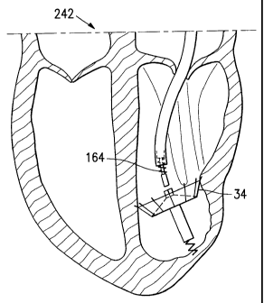
shaped body. A plurality of fibers 304 extend radially from an outer edge 306
of the
first cone-shaped body. An active anchor 308 extends down from the first hub
290.
[0092] The second frame 296 includes a plurality of segments 310 extending
radially and upwardly from the second hub 294 and end in sharp passive anchors
312. An attachment screw 314, similar to the detachment screw 164, extends
downwards from the second hub 294. Referring specifically to Figure 16B, the
attachment screw 314 is rotated so that it engages a pin 316 within the first
hub 290,
similarly to the frame hub 190 already described, to secure the second frame
296 to
the first frame 292. The second membrane 300 is made of ePTFE and stretched
between the segments 310 to form a second cone-shaped body.
[0093] Figure 16C illustrates a human heart with the cardiac device 288 of
Figure
16A secured to an akinetic portion thereof. The fibers 304 on the outer edge
306 of
the first frame 292 are interacting with an inner surface of the left
ventricle to seal off
the volume below the outer edge 306 of the first frame 292. The passive
anchors
312 on the ends of the segments 310 of the second frame 296 have penetrated
the
28
CA 02525433 2005-11-10
WO 2004/100803 PCT/US2004/014782
myocardium to hold the device 288 in place.
[0094] A further advantage of this embodiment is that the fibers 304 of the
first
membrane 298 interface with trabeculae and further block the flow of blood
into the
apex of the akinefiic portion.
[009] Figure 17A illustrates a cardiac device 318 according to a further
embodiment of the invention. The cardiac device 318 includes proximal 320 and
distal 322 hubs, a frame 324, a stem 326, a braided structure 328, and a
membrane
330. The frame 324 includes a plurality of segments 332 extending radially and
upwards from the distal hub 322, and the membrane 330 is stretched between the
segments 332 to form a cone-like body having an outer edge 334. Two extra
segments 336 extend across the outer edge 334 of the cone-like body and are
connected to and support the proximal hub 320 above the distal hub 322. The
stem
326, including an active anchor 338, extends downwards from the distal hub
322.
The braided structure 328 is made of nickel titanium and is connected to a
distal end
of the stem 326 into the ends of the segments 332. The segments 332 end in
sharp
passive anchors 340. The braided structure 328 may also be made of a
biodegradable material or a polymer.
[0096] Figure 17B illustrates a human heart with the cardiac device 318 of
Figure
17A having been secured to an akinetic portion thereof. The braided structure
328
presses against an inner surface of the left ventricle.
[0097] A further advantage of this embodiment is that the braided structure
328
allows the device to "nestle" into position before the active anchor 338 is
deployed to
secure the device 318 in place. Further advantages are that the braided
structure
328 adds structural stability to the device 318 and the nickel titanium of the
braided
structure 328 provides a mechanism for containing thrombi in the static
chamber.
29
CA 02525433 2005-11-10
WO 2004/100803 PCT/US2004/014782
[0098] Figure 18A illustrates a cardiac device 342 according to a further
embodiment of the invention. The cardiac device 342 includes proximal 344 and
distal 346 hubs, a frame 348, and a membrane 350. A plurality segments 352,
having first 354 and second 355 portions, extend upwardly and radially from
the
distal hub 346 in a curved fashion and are bent and extend inwards to meet at
fibs
proximal hub 344. The membrane 350 is stretched across the segments 352 to
form
a semi-circular or basket-shaped body. Sharp passive anchors 358 extend from
the
segments 352 between the first 354 and second 356 portions.
[0099] Some of the passive anchors 358 extend in a primarily axial direction
with a
small radial component, and some of the passive anchors 358 extend in a
primarily
radial direction with a small axial component. Other embodiments may have both
types of passive anchors on a single segment.
(00100] Figure 18B illustrates a human heart with the cardiac device 342 of
Figure
18A having been installed into an akinetic portion thereof. The segments 352
are
pressed against the myocardium because the device is slightly oversized.
[00101] A further advantage of this embodiment is that because of the size of
the
device 342 and shape of the segments 352, the passive anchors 358 are assisted
in
penetrating the myocardium. A further advantage is that because of the shape
of the
frame 348, the device 342 can be retrieved from the left ventricle as long as
the
device 34 is still attached to the deployment member 46. A further advantage
is that
because the entire frame 348 is covered with the membrane 350, the flow of
blood to
the apex of the akinetic portion is even further blocked.
[00102] Figure 19A illustrates a cardiac device 360 according to a further
embodiment of the invention. The cardiac device 360 includes a frame 362 and a
stem 364. The frame 362 includes a plurality of segments 366 which extend
CA 02525433 2005-11-10
WO 2004/100803 PCT/US2004/014782
upwardly and radially from the stem 364 and end in a plurality of sharp
passive
anchors 368. The stem 364 extends downwards from the frame 362 and includes
two suture strands 370 at a distal end thereof.
[00103] Figures 19B, 19C, and 19~ illustrate the installation ~f the cardiac
device
360 of Figure 16. ~IVhile a high pressure is maintained in the left ventricle
the
catheter tube 38 is inserted through the outer wall into the left ventricle
with the
cardiac device 360 inserted in the distal end thereof. The catheter 38 is
removed
from the cardiac device 360, and the cardiac device 360 expands such that the
passive anchors 368 are inserted into the inner surface of the left ventricle.
The
catheter 38 is then completely removed and the sutures 370 are used to close
the
insertion made by the catheter 38 and to secure the cardiac device 360 to the
akinetic portion.
[00104] Figures 20A, 20B, and 20C illustrate a cardiac device 372 according to
a
further embodiment of the invention. The cardiac device 372 includes a frame
hub
374, a frame 376, a membrane 378, and a stem 380. The frame hub 374 lies at a
central portion of the frame 376. The frame 376 includes a plurality of
segments 382
which extend radially and upwardly from the frame hub 374. A sharp passive
anchor
384 lies at the end of each of the segments 382. The membrane 378 is stretched
between the segments 382 to form a cone-shaped body. Before installation, the
stem 380 is unattached to the frame hub 374 and includes a proximal hub 386,
an
anchor hub 388, and a distal hub 390, each having a pin 392 extending across
an
inner surface thereof, similar to that of the frame hub 190. The proximal 386
and
distal 390 hubs are frictionally held near their respective ends in the stem
380, and
the anchor hub 388 is loose within the stem 380 so that it may move. An active
anchor 394 extends downwards from the anchor hub 388.
31
CA 02525433 2005-11-10
WO 2004/100803 PCT/US2004/014782
[00105] Figures 20D and 20E illustrate another embodiment of a distal end 396
of
a deployment member 398. The distal end 396 includes a detachment piece 400
and an attachment hub 402. The detachment piece 400 has been added to the
distal end of the outer torque shaft 152. The detachment piece 4.00 is a ring
shaped
body made of stainless steel with a length of 3 mm and an inner diameter
suitable to
frictionally hold the attachment hub 402, which is similar to the frame hub
190. An
attachment screw 404, similar to the detachment screw 164, extends downwards
from the attachment hub 402. Referring specifically to Figure 20E, forces
along the
length of the deployment member 398 will, by design, cause the attachment hub
402
to become dislodged from the detachment piece 400.
[00106] Figures 20F - 20H illustrate installation of the cardiac device 372 of
Figures 20A and 20B into a human heart. In this embodiment, the deployment
member used does not include the securing mechanism 166 so that the inner and
outer torque shafts may move axially relative to one another.
[00107] Before the device 372 and stem 380 are inserted into a heart, the
inner
torque shaft is passed through the frame hub 374, the proximal hub 386, and
the
anchor hub 388, and the outer torque shaft is positioned and rotated so that
the
attachment screw 404 engages both the pins 392 of the frame 374 and proximal
386
hubs, securing the cardiac device 372 to the stem 380. The device 372 and the
stem 380 are then retracted into the catheter 38 and steered into a left
ventricle. The
stem 380 is secured to an apex of an akinetic portion of a left ventricle of
the heart
by rotating the inner torque shaft, causing the active anchor 394 to penetrate
the
myocardium. Rotation of the outer torque shaft fihen causes the attachment
screw
404 to disengage the pin 392 of the proximal hub 386, and the device 372 is
released from the stem 380. However, the inner torque shaft remains engaged
with
32
CA 02525433 2005-11-10
WO 2004/100803 PCT/US2004/014782
the hubs in the stem 380.
[00108] Ifi it is determined that the stem 380 has been properly positioned,
the
cardiac device 372, secured t~ the outer torque shaft, is pushed over the
inner
torque shaft to meet the stem 380. The outer torque shaft is again restated s~
that
the attachment screw 404 reengages the pin 392 on the proximal hub 386 of the
stem, thus re-securing the stem 380 to the frame 376. The deployment member
398
is fihen forcibly pulled away fr~m the device 372 and the detachment piece 400
releases the attachment screw 404. Figure 201 illustrates the human heart with
the
cardiac device 372 of Figures 20A and 20B installed.
[00109] While certain exemplary embodiments have been described and shown in
the accompanying drawings, it is to be understood that such embodiments are
merely illustrative and not restrictive of the current invention, and that
this invention
is not restricted to the specific constructions and arrangements shown and
described
since modifications may occur to those ordinarily skilled in the art.
33