Note: Descriptions are shown in the official language in which they were submitted.
CA 02525535 2005-11-10
1
DESCRIPTION
APPARATUS FOR TRANSFERRING DATA VIA THE INTERNET
Technical Field
The present invention relates to a transfer apparatus for transferring
device data acquired from, for example, a sphygmomanometer to a server
connected to the Internet in a simple manner, and a method for transferring
device data using the same.
Background Art
FIG. 4 schematically shows a configur ation of a conventional device
data collection system. This data collection system includes a
sphygmomanometer 31 for measuring a blood pressure of a patient, a
personal computer 32 and a server 34 that is connected to the inter net 33 and
for accumulating blood pr essur a data.
The sphygmomanometer 31 is connected to the personal computer 32
via a serial cable 35. The personal computer 32 is connectable to the server
34 via the Internet 33. With this data collection system, it is possible to
accumulate blood pressure data indicating a patient's blood pressure
measured by the sphygmomanometer 31 in the server 34.
In the data collection system having the above-described
configuration, when the blood pressure of a patient is measured with the
sphygmomanometer 31, the blood pressure data indicating the measured
blood pressure are transferred via the serial cable 35 to the personal
computer 32. The blood pressure data transferred to the personal computer
32 are accumulated in the server 34 via the Internet 33.
With this data collection system, it becomes easier to collect the blood
pressure data of a patient who lives in a remote location, thus allowing a
doctor to diagnose a health condition relating to the blood pressure of the
CA 02525535 2005-11-10
2
patient who lives in a remote location (for example, see JP 2002-355305 A).
However, with such a configur anon of the data collection system, in
order to transfer the patient's blood pressure data measured with the
sphygmomanometer 31 to the server 34, it is necessary to operate the
personal computer 32 and connect it to the inter net 33. The personal
computer 32 has a long starting time from turning on a power until an
operable state is achieved. Also, for operating a software for transferring
the
blood pressure data to the server 34, the operations of input instruments such
as a mouse and a keyboard are complicated.
In particular, this is a serious problem if the patient is an elderly
person or is not accustomed to operating information instruments such as a
personal computer. In many cases, the patient whose blood pressure is
measured with the sphygmomanometer 31 is an elderly person who is not
accustomed to operating a per sonal computer or the like.
As a result, there has been a problem that it is difficult for the patient
who lives in a remote location to transfer his/ her own blood pressure data to
the server 34 via the Internet 33.
Disclosure of Invention
It is an object of the present invention to provide a data transfer
apparatus making it possible to transfer device data such as blood pressure
data acquired from a device such as a sphygmomanometer provided in a
remote location to a server connected to the inter net in an easy manner.
A data transfer apparatus according to the present inventian includes
a serial terminal for a serial connection to a target device for data
acquisition,
a data transfer terminal to be connected to a mobile phone so as to allow a
data transfer, a data acquisition portion for acquiring device data from the
tar get device for data acquisition by a serial communication via the serial
terminal, a data transfer portion for adding transmission instruction data to
the device data so as to create transfer data and transferring the transfer
CA 02525535 2005-11-10
3
data via the data transfer terminal, and a control portion for executing an
open anon of acquiring the device data by the data acquisition portion and an
open ation of tr ansferring the transfer data by the data tr ansfer por tion.
The
transmission instruction data correspond to an instruction to cause the
mobile phone to conduct an operation of transmitting the device data to a
predetermined server via the Internet.
Brief Description of Drawings
FIG. 1 is a block diagram schematically showing a configuration of a
data collection system using data transfer apparatuses in an embodiment of
the present invention.
FIG. 2 is a block diagr am showing the configur anon of the
above-mentioned data transfer apparatus.
FIG. 3 is a perspective view showing an external appearance of the
above-mentioned data transfer apparatus.
FIG. 4 schematically shows a configuration of a conventional data
collection system.
Description of the Invention
With the data transfer apparatus according to the present invention,
device data acquired from a device such as a sphygmomanometer can be
transferred from a mobile phone via the inter net to a predetermined server
by a simple operation.
The data transfer apparatus according to the present invention
preferably is constituted so that an activation switch is provided, and by an
operation of the activation switch, the control portion starts the operation
by
the data acquisition portion and the operation by the data transfer portion.
Also, it is preferable further to include a memory storing a serial
number for distinguishing the data transfer apparatus from one another, and
that the data transfer portion adds the serial number to the device data so as
CA 02525535 2005-11-10
4
to create data to be transmitted to the server.
Further, the data transfer portion preferably has a configuration
including an emulator for converting data into an emulation code according to
a keyboard emulation format for operating the mobile phone, and converting
the tr ansfer data into the emulation code and tr ansfer r ing the emulation
code.
In this configur anon, it is preferable that the data tr ansfer portion
has a data creation portion and a transfer processing portion, the data
creation portion creates data containing the device data and the transmission
instruction data and supplies them to the transfer processing portion, and the
transfer processing portion converts the data supplied from the data creation
portion into the emulation code and outputs the emulation code from the data
transfer terminal.
Furthermore, in the data transfer apparatus according to the present
invention, it is preferable that the control portion has a function of
detecting
whether connection states with respect to the target device for data
acquisition and the mobile phone are good or bad, and a display portion is
provided for indicating whether the connection states are good or bad by a
blinking state controlled by the control portion.
In the data transfer apparatus according to the present invention, the
target device for data acquisition can be a medical instrument, an electric
meter for measuring an electricity consumption amount, a water meter for
measuring a running water consumption amount, production equipment
capable of outputting log data or an electric home appliance capable of
outputting data indicating an operation state. The medical instrument can
be a sphygmomanometer, a pulsimeter or a blood sugar level meter.
A method for tr ansferr ing device data actor ding to the present
invention is a method using the data transfer apparatus having any of the
configurations described above so as to transfer the device data acquired from
the tar get device for data acquisition from the mobile phone via the inter
net.
CA 02525535 2005-11-10
The method is executed by a procedure including turning on a power source
of the mobile phone, turning on a power source of the data transfer apparatus
and a power source of the target device for data acquisition, connecting the
data transfer apparatus to the target device for data acquisition by a serial
5 cable, and connecting the data transfer apparatus to the mobile phone by a
transfer cable, in any order, followed by activating the control portion of
the
data transfer apparatus.
The following is a specific description of an embodiment of the present
invention, with reference to the accompanying drawings.
FIG. 1 schematically shows a configur ation of a data collection system
using data transfer apparatuses in the present embodiment. This data
collection system is for collecting blood pressure data obtained by measuring
the blood pressure of individual patients from a plurality of
sphygmomanometers 1. Each of the sphygmomanometers 1 is connected to
a data transfer apparatus 3 via a serial cable 2. Each of the data transfer
apparatuses 3 is connected to a mobile phone 5 via a transfer cable 4. Each
of the mobile phones 5 is connectable to the inter net 6.
The data collection system further includes a server 7 connected to
the Internet 6 for accumulating blood pressure data measured with each of
the sphygmomanometer s 1 and a personal computer for a doctor (in the
following, referred to as a doctor PC) 8 that is connectable to the inter net
6.
The doctor PC 8 is provided for allowing a doctor to analyze the blood
pressure data accumulated in the server 7.
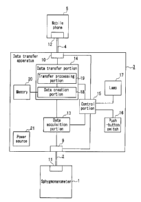
FIG. 2 is a block diagram showing a configuration of the data transfer
apparatus 3 and a connection structure with the sphygmomanometer 1 and
the mobile phone 5. The data transfer apparatus 3 includes a serial
terminal 9 connected to one end of the serial cable 2 and a transfer terminal
10 connected to one end of the tr ansfer cable 4. The other end of the ser ial
cable 2 is connected to a serial terminal 11 provided in the
sphygmomanometer 1. The other end of the transfer cable 4 is connected to
CA 02525535 2005-11-10
G
a terminal 12 in the mobile phone 5. Respective cables and terminals can be
connected or disconnected freely.
The data transfer apparatus 3 has a data acquisition portion 13, a
data transfer portion 14 and a control portion 15 as major elements. These
elements can be configured with a microprocessor. The data acquisition
portion 13 is supplied with an output of the sphygmomanometer 1 via the
serial terminal 11, the serial cable 2 and the serial ter urinal 9. An output
of
the data acquisition portion 13 is supplied to the data transfer portion 14.
An output of the data transfer portion 14 is supplied to the mobile phone 5
via the transfer terminal 10, the transfer cable 4 and the transfer terminal
12.
The control portion 15 controls operations of the data acquisition portion 13
and the data transfer portion 14.
A push-button switch 6 is connected to the control portion 15, and by
an operation thereof, the control portion 15 exerts control so as to start a
series of operations performed by the data acquisition portion 13 and the data
transfer portion 14. The control portion 15 is connected to the serial
terminal 9 and the transfer terminal 10 and determines whether a connection
state of the serial cable 2 and that of the transfer cable 4 are good or bad.
Since the determination method can be any usual methods, the specific
description thereof will be omitted. The result of the determination is
indicated by a lamp 17.
The data acquisition portion 13 is activated by the control of the
control portion 15, automatically acquires the measured blood pressure data
and sphygmomanometer data containing data specifying the date and time of
measuring the blood pressure from the sphygmomanometer 1 and supplies
them to the data transfer portion 14.
The data transfer portion 14 includes a data creation portion 18 and a
transfer processing portion 19. The data transfer portion 14 is connected to
a memory 20, and the memory 20 stores a serial number for identifying the
individual data transfer apparatus 3 and transmission instruction data. The
CA 02525535 2005-11-10
7
data creation por tion 18 cr Bates tr ansfer data by adding the ser ial number
and the transmission instruction data obtained from the memory 20 to the
sphygmomanometer data obtained from the data acquisition portion 13, and
supplies it to the transfer processing portion 19. The transfer processing
170Tt10I1 19 converts the transfer data into an emulation code representing a
state in which a key or the like of the mobile phone 5 is pressed and
transfers
it to the mobile phone 5 according to a keyboard emulation format.
Based on the transmission instruction data contained in the
transferred data, the mobile phone 5 carries out a processing for connecting
to the Internet 6 and a processing for transmitting the sphygmomanometer
data and the serial number to the server 7. As a result, the
sphygmomanometer data and the serial number are transferred from the
mobile phone 5 via the inter net 6 to the server 7.
Transfer processing from the mobile phone 5 is carried out based on a
POST/GET method of the Internet, for example. Thus, the transmission
instruction data stored in the memory 20 of the data transfer apparatus 3
contain data regarding a menu selection of the mobile phone 5, an initiation
of a function of the mobile phone 5 for connection to the Internet and the
connection, and a input of URL of the server to which the data are to be
transferred. The transfer processing portion 19 converts these transmission
instruction data and numerical values of the sphygmomanometer data and
the serial number into an emulation code and outputs this emulation code.
It should be noted that, in the case where the mobile phone 5 has an emulator,
the conversion processing by the transfer processing portion 19 is not
necessary.
Apower source 21 provided in the data transfer apparatus 3 is
constituted by, for example, a dry battery and supplies a voltage for open
ating
the data acquisition portion 13, the data transfer portion 14, the control
portion 15, the lamp 17 and the memory 20.
FIG. 3 is a perspective view showing an external appearance of the
CA 02525535 2005-11-10
8
data transfer apparatus 3 according to the present embodiment. The data
transfer apparatus 3 has a substantially rectangular shape, and the
push-button switch 16 having an elliptical shape is provided at the center of
an upper surface of the data transfer apparatus 3. The lamp 17 having a
crescent shape is provided adjacent to the push-button switch 16.
The open ation of the data collection system configured as above will
be described. When the power source of the data transfer apparatus 3 is
turned on, the control portion 15 detects whether the connection states of the
serial cable 2 and the transfer cable 4 are good or bad. If the connection
state is good, the lamp 17 is made to light up. If the connection state of the
serial cable 2 or the transfer cable 4 is bad, the lamp 17 is made to blink.
In
this way, it is possible to adjust the connection state of the serial cable 2
or
the transfer cable 4, thereby preventing a transfer error of the
sphygmomanometer data caused by a poor connection.
Next, when a patient pushes down the push-button switch 16, the
data acquisition portion 13 acquires the sphygmomanometer data measured
with the sphygmomanometer 1 by serial communication. The acquired
sphygmomanometer data are supplied to the data transfer portion 14.
Subsequently, the data transfer portion 14 first causes the data
creation portion 18 to add the serial number and the transmission instruction
data stored in the memory 20 to the sphygmomanometer data and then
supplies them to the transfer processing portion 19. The transfer processing
portion 19 converts the data actor ding to the keyboar d emulation format of
the mobile phone 5 and tr ansfer s them to the mobile phone 5.
The mobile phone 5 carries out an operation for connection to the
Internet 6 according to the transmission instruction data in the tr ansfer
data
r eceived from the data tr ansfer portion 14 and an operation of transmitting
the sphygmomanometer data and the serial number via the inter net 6 to the
server 7. Then, the server 7 receives and accumulates the
sphygmomanometer data and the serial number transmitted from each
CA 02525535 2005-11-10
9
mobile phone 5.
As a result, it becomes possible to acquire the sphygmomanometer
data accumulated in the server '7 via the Internet 6 and analyze them with
the doctor PC 8.
As described above, with the data collection system according to the
present embodiment, the data transfer apparatus 3 substantially
automatically transfers the sphygmomanometer data measured with the
sphygmomanometer 1 from the mobile phone 5 via the Internet 6 to the
server 7. Thus, the sphygmomanometer data can be transmitted in a simple
manner without using a personal computer whose operation is complicated.
In other words, the operation of the data transfer apparatus 3 only involves
the connections of the serial cable 2 and the transfer cable 4 and a single
push of the push-button switch 16 and, thus, is extremely easy.
Further, since the data transfer apparatus 3 is operated by the power
source 21 constituted by a dry battery, it is easy to handle. The mobile
phone to be connected to the data transfer apparatus 3 is widespread and
easily available and, because of its small size, easy to handle. Accordingly,
for example, it is easy for a patient in a r emote location to measure his/
her
own blood pressure with the sphygmomanometer 1 three or four times a day
everyday and transmit the sphygmomanometer data to the server 7 every
time the blood pressure is measured. Alternatively, it also is easy to
transmit the sphygmomanometer data for one day at one time to the server 7.
The following is an example of an operation procedure at the time of
tr ansmission. First, the power sour ce of the mobile phone 5 is tur ned on,
and then the power source of the data transfer apparatus 3 and that, of the
sphygmomanometer 1 are turned on. Next, the data transfer apparatus 3
and the mobile phone 5 are connected by the transfer cable 4, and the data
transfer apparatus 3 and the sphygmomanometer 1 are connected by the
serial cable 2. Thereafter, when the push-button switch 16 of the data
transfer apparatus 3 is pushed down, the blood pressure data that have been
CA 02525535 2005-11-10
measured and accumulated in the sphygmomanometer 1 by then are
tr ansmitted automatically from the sphygmomanometer 1 via the mobile
phone 5 and the Internet 6 to the server 7.
Further, since the sphygmomanometer data and the serial number
5 transmitted from the mobile phone 5 via the Internet 6 to the server 7
consist
of a string of numerals, it is not possible to determine the ID of a patient
even
if these data are intercepted on the inter net 6. Consequently, the privacy of
the patient can be protected.
A doctor can specify the patient only after he/ she matches the serial
10 number transferred to the server and a patient ID. The above-noted serial
number is given to each data transfer apparatus 3, and thus, no means for
identifying a sphygmomanometer or a mobile phone is needed. For example,
it is not necessary to input an ID to the sphygmomanometer or the mobile
phone, so that the operation is simple. Also, since one data transfer
apparatus can be made to correspond to one patient, the sphygmomanometer
and the mobile phone can be shared among a plurality of patients.
Furthermore, a doctor instantly can analyze the blood pressure data collected
in the server 7 using the doctor PC 8, so that any abnormal values in the
blood pressure data can be recognized in a timely manner. Consequently,
the doctor can start a treatment on the patient immediately.
Although the above-described embodiment has been directed to an
example in which the data tr ansfer apparatus 3 is connected to the
sphygmomanometer 1, the present invention is not limited to this. In other
words, any electric appliances can be connected to the data transfer
apparatus 3 according to the present embodiment so as to obtain a similar
effect as long as it is capable of transferring data to be handled by serial
communication. For example, the data transfer apparatus may be connected
to other medical instruments such as a pulsimeter for measuring a patient's
pulsation, a dialysis unit and a blood sugar level meter.
Moreover, the data transfer apparatus 3 may be connected to an
CA 02525535 2005-11-10
ll
electric meter for measuring an electricity consumption amount, a water
meter for measuring a running water consumption amount or the like.
Alternatively, the data transfer apparatus 3 can be connected to production
equipment for producing articles, and log data associated with an operation
state of the production equipment can be transferred. Alternatively, the
data transfer apparatus 3 can be connected to an electric home appliance,
and data indicating an operation state of the electric home appliance, for
example, data indicating whether or not a battery is exhausted can be
transferred.
Industrial Apt~licability
In accordance with the present invention, it is possible to provide a
data transfer apparatus making it possible to transfer device data such as
sphygmomanometer data acquired from a device such as a
sphygmomanometer provided in a remote location to a server connected to
the Internet in an easy manner.