Note: Descriptions are shown in the official language in which they were submitted.
CA 02525997 2005-11-08
89019-14
TITLE: METHOD AND SYSTEM FOR SCREENING CARGO
CONTAINERS
FIELD OF THE 1NVENT10N
The present invention relates generally to container contents verification
and, more
particularly, to methods, systems and devices for verifying the contents of
containers,
preferably large shipping containers.
l0 BACKGROUND
Everyday, thousands of cargo containers arrive at various destinations around
the world,
be it at airports, train stations, ports, buildings and other public or
private venues. The
containers are used to carry a broad range of items including, but not limited
to, vehicles,
food, livestock and clothing.
The global economy necessitates that cargo containers for import and export
trade be
moved in a manner that assures a nation's citizens and the foreign trading and
business
community that the risk experienced will be at acceptable and predictable
levels. As such
assuring a safe and efficient flow of cargo containers is critical to a
vibrant global
economy.
The basic tool today for monitoring cargo containers is the manifest.
Typically, the cargo
manifest describes, amongst other things, the objects expected to be present
in the cargo
container. The cargo manifest is the basis of commercial agreements, e.g.,
assuring that
what is shipped is what ultimately arrives at its destination. The cargo
manifest is
typically also the basis of monitoring hazardous cargo stowage, proper freight
rate
assessments and assessing customs duties. The United States government has
recently
implemented a program called CSI (Container Security Initiative) which makes
use of the
manifest of selected containers at foreign ports before these ones are shipped
to the U.S.
1
CA 02525997 2005-11-08
89019-14
A first deficiency associated with the use of a cargo manifest alone for
assessing the
content of a cargo container is the possibility of cargo theft. Cargo theft is
the removal of
one or more items from the cargo container after the manifest has been
created. As such,
the content of the cargo container at the departure location is different from
the content of
the cargo container at the arrival location. A method typically used for
remedying this
deficiency is to close the cargo container with a seal or with "smart" door
sensors.
"Smart" door sensors are typically adapted to detect changes in light
intensity or other
changes in the internal environment of the container. It follows therefore, in
theory, that
if the seal of a cargo container is not broken or if no change in light
intensity or in the
1 o internal environment of the container was detected, the content of that
cargo container
should match the expected content of the cargo container as it is expressed in
the
manifest.
A second deficiency associated with the use of a cargo manifest is the
possibility of
manifest fraud. Manifest fraud includes the introduction of illicit cargo
(arms, drugs,
people, counterfeit objects) in a cargo container after the manifest has been
created or the
omission from the manifest of already present cargo. As such, the actual
content of the
container at the departure location is different from that expressed in the
manifest. As
can be readily appreciated, the above-described deficiency is not corrected by
applying a
seal to the cargo container or by the use of "smart" door sensors.
The use of a cargo manifest in a non-complex environment in which there is no
possibility of fraud or deceitful actions may be adequate, but in complex
environments,
its use becomes increasingly inadequate and insecure. As such, even if a cargo
container
is associated to a manifest and is sealed, its actual content may be different
from that
expressed by the manifest. For that reason, verification of the content of a
cargo
container is required to ensure that the contents correspond to the manifest.
In practice, such verification is performed manually by having a customs
agent, or a port
official, break the seal of the cargo container and make a visual inspection
of its content
on the basis of the manifest. As can be readily appreciated, such a procedure
is time
2
CA 02525997 2005-11-08
89019-14
consuming and costly both from a human resource perspective (since customs or
security
agents must be hired to perform this inspection) as well as from an economic
perspective,
since the cargo containers are delayed in transit waiting to be screened. For
that reason,
not all cargo containers are screened but rather a small percentage of the
containers
(about 4 % in 2005) are screened in the manner described above. The manner in
which
cargo containers are selected for screening varies from random selection to
selections
based on risk factors (origin, type of shipment, destination, etc...).
However, a large
number of cargo containers go unscreened leaving a loophole available for
smuggling (of
drugs, arms and people), manifest fraud and other unlawful activities. As
terrorism and
1 o smuggling increase, the potential problems that such a loophole allows are
significant not
only from an economic standpoint but also from a national security
perspective.
A proposed solution to the above is described in U.S. patent no. 6,370,222,
issued April
9, 2002 to Cornick, Jr. and assigned to CCVS, LLC, Annandale VA (US). More
specifically, U.S. patent no. 6,370,222 describes a method and system for
verifying the
contents of a cargo container which includes acquiring at the departure port
at least one
image of the cargo container and of the contents of the cargo container and
storing the
image with a manifest associated with the cargo container. The manifest is
sent to another
location, say to the arrival port, and, at the other location, selectively, a
second image of
2o the contents of the cargo container is acquired and compared with the
original image
stored with the manifest associated with the cargo container.
A deficiency with the above described solution is that it requires obtaining
two (2)
images of the cargo container - one at the departure port and one at the
arrival port. As
such, the above-described system requires that both the departure and arrival
locations be
equipped with similar equipment and imaging capabilities. Since the departure
and
arrival locations may be located in different countries, providing this type
of coordination
may be prohibitively complex and is impractical. Another deficiency associated
to the
above-described method is that it generally requires a human operator to
effect a
3o comparison between the images and the manifest which is time consuming and
costly.
3
CA 02525997 2005-11-08
89019-14
Consequently, there is a need in the industry for providing a method and
system for use
in screening cargo containers to verify the contents thereof that alleviate at
least in part
the deficiencies of the prior art.
SUMMARY OF THE INVENTION
In accordance with a broad aspect, the invention provides a system for
screening cargo
containers. The system comprises an image generation device suitable for
generating an
image signal associated with a cargo container, the image signal conveying
information
l0 related to the contents of the cargo container. The system also comprises
an apparatus
including a first input for receiving the image signal associated with the
cargo container,
a second input for receiving a list of objects conveying objects expected to
be present in
the cargo container and a processing unit. The processing unit is operative
for processing
the image signal associated with the cargo container in combination with the
list of
t5 objects and a group of target images associated with objects to derive
mismatch
information data. The mismatch information data conveys at least one
distinction
between the list of objects and the information related to the contents of the
cargo
container conveyed by the image signal. The apparatus includes an output for
releasing
information conveying the mismatch information data. The system includes an
output
20 module for conveying to a user of the system information derived at least
in part on the
basis of the mismatch information data.
In accordance with a specific implementation, list of objects is a first list
of objects. The
processing unit processes the image signal associated with the cargo container
in
25 combination with the group of target images associated with objects to
detect a presence
of at least one object in the cargo container. The processing unit then
generates a second
list of objects conveying objects whose presence in the container was
detected. The
processing unit then compares the second list of objects with the first list
of objects to
derive the mismatch information data. The mismatch information data may convey
an
30 object present in the first list of objects but absent from the second list
of objects.
4
CA 02525997 2005-11-08
89019-14
Alternatively, the mismatch information data may convey an object present in
the second
list of objects (i.e. detected in the container) but absent from the first
list of objects.
In a specific implementation, the first list of objects is derived from a
manifest associated
with the container. In a specific implementation, the cargo container is
associated to a
cargo identifier data element and the processing unit processes the cargo
identifier data
element in combination with a cargo container database including a plurality
of manifest
to identify a manifest associated with the cargo container.
l0 In accordance with a specific implementation, the processing unit processes
a database of
target images on the basis of the first list of objects to derive the group of
target images,
the group of target images being indicative of a subset of the database of
target images.
Advantageously, this allows reducing the number of target images in the
database that are
processed in combination with the image signal.
IS
In a specific implementation, the output module includes a display screen for
conveying
to a user of the system information derived at least in part on the basis of
the mismatch
information in visual format. Alternatively, the output module includes an
audio output
for conveying to a user of the system information derived at least in part on
the basis of
2o the mismatch information in audio format.
In a specific implementation, the processing unit is operative for generating
log
information data elements conveying the mismatch information and storing the
log
information data elements on a computer readable storage medium. The log
information
25 may include a time stamp data element indicating timing information
associated to the
cargo container or any other suitable type of information. The timing
information may be
the time at which the cargo container arrived at a certain location, the time
at which the
cargo container was screened and/or the time at which the mismatch information
was
generated.
5
CA 02525997 2005-11-08
89019-14
In a specific example of implementation, the apparatus is operative for
effecting a
correlation operation between data derived from the image signal and at least
one target
image in the group of target images. The correlation operation may be effected
optically,
by using an optical correlator, or digitally using a programmed digital
computer or
dedicated hardware. In an alternative example of implementation, the
comparisons
between the image signal associated with the cargo container and at least some
images in
the plurality of target images is effected using any suitable image processing
algorithm.
In a specific example of implementation, the image generation device uses
penetrating
to radiation or emitted radiation to generate the image associated with the
cargo container.
Examples include, but are not limited to, x-ray, gamma ray, computed
tomography (CT
scan), thermal imaging and millimeter wave. The image signal generated may
also be in
any suitable format such as for example, VGA, SVGA, XGA, JPEG, GIF, TIFF and
bitmap amongst others. The image signal associated with the cargo container is
a two
dimensional image or a three-dimensional image.
In accordance with a specific implementation, the group of target images
includes data
elements indicative of Fourier transforms of target images and the processing
unit
includes an optical correlator. The optical correlator is operative for
processing the
image signal associated with the cargo container to derive a first Fourier
transform data
element indicative of a Fourier transform of the image signal associated with
the cargo
container. The optical correlator also computes a correlation operation
between the first
Fourier transform data element and the Fourier transform of at least one
target image to
detect a presence of the at least one target object in the cargo container.
In accordance with another broad aspect, the invention provides a method for
screening a
cargo container. The method comprises receiving an image signal associated
with the
cargo container, the image signal conveying information related to contents of
the cargo
container. The method also comprises receiving a list of objects conveying
objects
expected to be present in the cargo container. The method also comprises
processing the
image signal associated with the cargo container in combination with the list
of objects
6
CA 02525997 2005-11-08
89019-14
and with a group of target images associated with objects to derive mismatch
information
data. The mismatch information data conveys at least one distinction between
the list of
objects and the information related to the contents of the cargo container
conveyed by the
image signal. The method also includes releasing information conveying the
mismatch
information data.
In accordance with another broad aspect, the invention provides and apparatus
suitable
for screening cargo containers in accordance with the above described method.
1o In accordance with another broad aspect, the invention provides a computer
readable
storage medium including a program element suitable for execution by a
computing
apparatus for screening cargo containers, the computing apparatus comprising a
memory
unit and a processor operatively connected to the memory unit. The program
element
when executing on the processor is operative for receiving an image signal
associated
with the cargo container, the image signal conveying information related to
the contents
of the cargo container. The program element, when executing on the processor,
is also
operative for receiving a first list of objects conveying objects expected to
be present in
the cargo container. The program element, when executing on the processor, is
also
operative for causing the image signal associated with the cargo container to
be processed
in combination with a group of target images associated with objects to detect
a presence
of at least one object in the container. The program element when executing on
the
processor is also operative for generating a second list of objects, the
second list of
objects conveying objects whose presence in the container was detected. The
program
element, when executing on the processor, is also operative for comparing the
second list
of objects with the first list of objects to derive mismatch information data
conveying at
least one distinction between the first list of objects and the second list of
objects. The
program element when executing on the processor is operative for releasing
information
conveying the mismatch information data.
3o In accordance with yet another broad aspect, the invention provides an
apparatus for
screening a cargo container. The apparatus comprises means for receiving an
image
7
CA 02525997 2005-11-08
89019-14
signal associated with the cargo container, the image signal conveying
information
related to the contents of the cargo container. The apparatus also comprises
means for
receiving a list of objects conveying objects expected to be present in the
cargo container.
The apparatus also comprises means for processing the image signal associated
with the
cargo container in combination with the list of objects and with a group of
target images
associated with objects to derive mismatch information data. The mismatch
information
data conveys at least one distinction between the first list of objects and
the information
related to the contents of the cargo container conveyed by the image signal.
The
apparatus also provides means for releasing information conveying the mismatch
1 o information data.
In accordance with yet another broad aspect, the invention provides an
apparatus for
authenticating the contents of a cargo container. The apparatus comprises a
first input for
receiving data conveying graphic information regarding the contents of the
container and
a second input for receiving data conveying an expected content of the
container. The
apparatus also comprises an optical correlator and a processing unit. The
optical
correlator is operative for processing the graphic information to detect
depictions of one
or more objects in the container. The processing unit is operative for
generating a list of
objects detected in the container by the optical correlator and for processing
the list of
objects detected in the container in combination with the data conveying an
expected
content of the container to derive mismatch information data. The mismatch
information
data conveys at least one distinction between the list of objects detected in
the container
and the data conveying an expected content of the container. The apparatus
also includes
an output for releasing a signal conveying the mismatch information data.
For the purpose of this specification, the expression "cargo container" is
used to broadly
describe an enclosures for storing cargo such as would be used, for example,
in a ship,
train, truck, van, or an other suitable type of cargo container. The
expression "cargo
container" extends to a receptacle for the storage or transportation of goods,
and includes
3o freight pallets as well as vehicles, whether motorized or drawn, such as
automobiles, the
8
CA 02525997 2005-11-08
89019-14
cab and trailer of a truck, railroad cars or ship-borne containers.
In accordance with yet another broad aspect, the invention provides a method
for
verifying the contents of a cargo container. The method comprises receiving at
a first
location a manifest conveying objects expected to be present in the cargo
container, the
manifest having been sent from a second location geographically distinct from
the first
location. The method also comprises acquiring at the first location an image
signal
associated with the cargo container, the image signal conveying information
related to
contents of the cargo container. The method also comprises processing the
image signal
1o associated with the cargo container in combination with the manifest and a
group of
target images to verify the contents of the cargo container.
Other aspects and features of the present invention will become apparent to
those
ordinarily skilled in the art upon review of the following description of
specific
embodiments of the invention in conjunction with the accompanying Figures.
BRIEF DESCRIPTION OF THE DRAWINGS
A detailed description of the embodiments of the present invention is provided
herein
below, by way of example only, with reference to the accompanying drawings, in
which:
Figure I is a high-level block diagram of a system for screening a cargo
container in
accordance with a specific example of implementation of the present invention;
Figure 2 is a block diagram of an output module suitable for use in connection
with the
system depicted in Figure 1 in accordance with a specific example of
implementation of the present invention;
Figure 3 is a block diagram of an apparatus for processing images suitable for
use in
3o connection with the system depicted in Figure 1 in accordance with a
specific
example of implementation of the present invention;
9
CA 02525997 2005-11-08
89019-14
Figure 4 depicts a specific example of a visual representation conveying
mismatch
information data in accordance with specific examples of implementation of the
present invention;
Figure 5 is a flow diagram depicting a process for screening a cargo container
in
accordance with a specific example of implementation of the present invention;
Figure 6 is a flow diagram depicting a process for deriving mismatch
information data for
1o a cargo container in accordance with a specific example of implementation
of the
present invention;
Figure 7 shows three images associated to a object suitable for use in
connection with the
system depicted in Figure 1, each image depicting the target object in a
different
orientation, in accordance with a specific example of implementation of the
present invention;
Figure 8 shows a mosaic image including a plurality of sub-images associated
with an
object suitable for use in connection with the system depicted in Figure 1,
each
2o sub-image depicting the target object in a different orientation and scale,
in
accordance with a specific example of implementation of the present invention;
Figure 9 is a functional block diagram a cargo container screening system
including an
optical correlator in accordance with a specific example of implementation of
the
present invention;
Figure 10 is a block diagram depicting the functioning of an optical
correlator in
accordance with a specific example of implementation of the present invention;
3o Figure 11 depicts a Fourier transform, amplitude and phase, of the spatial
domain image
for number 2;
CA 02525997 2005-11-08
89019-14
Figure 12 is a block diagram of an apparatus suitable for implementing at
least a portion
of the modules depicted in connection with the apparatus for processing images
shown in Figure 3 in accordance with a specific example of implementation of
the
present invention;
Figure 13 is a block diagram of an alternative implementation of an apparatus
suitable for
implementing at least a portion of the modules depicted in connection with the
apparatus for processing images shown in Figure 3 in accordance with a
specific
example of implementation of the present invention;
Fig. 14 shows a functional block diagram of a client-server system suitable
for use in
screening a cargo container in accordance with an alternative specific example
of
implementation of the present invention.
In the drawings, the embodiments of the invention are illustrated by way of
examples. It
is to be expressly understood that the description and drawings are only for
the purpose
of illustration and are an aid for understanding. They are not intended to be
a definition of
the limits of the invention.
DETAILED DESCRIPTION
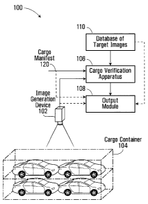
Shown in Figure 1 is a system 100 for screening a cargo container in
accordance with a
specific example of implementation of the present invention. The system 100
includes an
image generation device 102, an apparatus 106 in communication with the image
generation device 102 and an output module 108.
The image generation device 102 generates an image signal associated with a
cargo
container 104. The image signal conveys information related to the contents of
the cargo
3o container 104. The apparatus 106 receives the image signal associated with
the cargo
11
CA 02525997 2005-11-08
89019-14
container 104. The apparatus 106 also received at input 120 a list of objects
conveying
objects expected to be present in the cargo container.
The apparatus 106 processes the image signal associated with the cargo
container in
combination with the list of objects and a group of target images associated
with objects
to derive mismatch information data. The mismatch information data conveys
distinctions, if any, between the list of objects 120 expected to be present
in the cargo
container 104 and information related to the contents of the cargo conveyed by
the image
signal generated by the image generation device 102. In a specific
implementation, the
group of target images is stored in a database of target images 110. Examples
of the
manner in which the mismatch information data can be derived are described
later on in
the specification. The output module 108 conveys information derived at least
in part on
the basis of the mismatch information data to a user of the system.
Advantageously, the system 100 provides assistance to cargo screening
personnel in
verifying the content of cargo containers and in identifying discrepancies
between the
manifest of the cargo container and the actual content of the cargo container.
In addition,
this verification is performed without requiring that the seal of the cargo
container be
broken and without requiring that an opening be made on the cargo container
body.
As described above, a list of objects expected to be present in the cargo is
received at
input 120. The list of objects at input 120 may be provided in any suitable
format
capable of conveying a set of objects expected to be in cargo container 104.
In the
specific implementation depicted in the figure, the list of objects is derived
from a cargo
manifest associated with the cargo container 104. The list of objects may be
in electronic
format, paper format and may be in the form of text, images, a combination of
text and
images or in any other suitable format. In a specific practical
implementation, the list of
objects received is converted into a standard electronic format for ease of
processing by
the cargo verification apparatus 106. In a non-limiting implementation, the
input 120
3o may be part of a computing terminal including a user interface allowing the
list of objects
120 to be entered either electronically (electronic file or otherwise) or
manually
12
CA 02525997 2005-11-08
89019-14
(scanning, keyboard, mouse, ASR (automatic speech recognition)) and
communicated to
cargo verification apparatus 106. In an alternative non-limiting
implementation, the input
120 is in communication with a network (LAN, WAN or other) and may receive
data
conveying the list of objects over that network. In yet another alternative
implementation
(not shown in the figures), the input 120 is in communication with a database
of cargo
manifests including a plurality of entries, each entry being associated to a
respective
cargo container. The apparatus 106 is adapted to receive an identifier data
element
associated to a cargo container 104 and extract a cargo manifest from the
database of
cargo manifests on the basis of this identifier data element. The identifier
data element
l0 may be provided through in any suitable user interface including, but not
limited to,
optical scanners (eg. bar code), keyboard, pointing device, touch sensitive
screen and
voice inputs (ASR).
Image Generation Device 102
In a specific example of implementation, the image generation device 102 uses
penetrating radiation or emitted radiation to generate the image associated
with the cargo
container 104. The radiation can be of any wavelengths and energies (e.g. any
bands) of
the electromagnetic spectrum. Specific examples of image generation devices
that may
be used include, without being limited to, x-ray, gamma ray, computed
tomography (CT
scans), thermal imaging and millimeter wave devices. Such devices are known in
the art
and as such will not be described further here. In a non-limiting example of
implementation, the image generation device 102 is a conventional x-ray
machine
adapted for generating an x-ray image of the cargo container 104.
In a first specific example of implementation, the image generation device 102
is
operative for acquiring an image conveying a single view of the cargo
container. In a
3o non-limiting example of implementation, the image generation device 102 is
operative
for acquiring an image of the cargo container along an axis running the length
of the
13
CA 02525997 2005-11-08
89019-14
cargo container. This type of screening is particularly useful when the
objects stored
within the container are organized in a single layer in the image plane or in
multiple
layers on the image plane with no objects occluded by others. Examples of
objects that
can be screened using an image of the cargo container along a single axis
include
vehicles such as cars, trucks, personal watercraft devices, snowmobiles,
motorcycles and
other vehicles transported via containers. Other examples include any large
objects with
a distinct signature (e.g. shape, density, color, texture, etc.)
In a second specific example of implementation, the image generation device
102 is
t0 operative for acquiring multiple views of the cargo container. In a non-
limiting example
of implementation, the image generation device 102 is operative for acquiring
a first view
of the cargo container along a first axis running the length of the cargo
container and a
second view of the cargo container along a second axis running the depth of
the cargo
container. The combination of the first and second image allows obtaining a
more
complete indication of the contents of the cargo container. This type of
screening is
particularly useful when objects stored within the container are occluded,
partially or
completely, by others in the image plane.
In a third specific example of implementation, the image generation device 102
is
operative for acquiring multiple views of the cargo container along a same
axis axes but
at different depths. Computed tomography scans (CT scans), for example, are
particularly useful in such cases. In a non-limiting example of
implementation, the image
generation device 102 is operative for acquiring a first image of the cargo
container along
an axis running the length of the cargo container at a first depth and a
second image of
the cargo container along the same axis running the length of the cargo
container at a
second depth. This type of screening is particularly useful when objects
stored within the
container are organized in multiple layers and occluded by others in a given
image plane.
In a fourth specific example of implementation, the image generation device
102 is
operative for acquiring multiple views of a same surface of the cargo
container but at
different angles. In a non-limiting example of implementation, the image
generation
14
CA 02525997 2005-11-08
89019-14
device 102 is operative for acquiring a first image of the cargo container
along an axis
running the length of the cargo container at a specific angle (say at an angle
perpendicular
to the surface of the cargo container) and a second image of the cargo
container along the
same axis but at a different angle (say at an angle of 45° to the
surface of the cargo
container). This type of screening is particularly useful to better pin point
the location of
an object in its image plane and allowing to see an object that would
otherwise be hidden,
while providing a 3-D effect.
In a fifth specific example of implementation, the image generation device 102
is
operative for acquiring multiple images of the cargo container along a single
axis but
using different beam intensities. In a non-limiting example of implementation,
the image
generation device 102 is operative for acquiring images of the cargo container
along an
axis running the length of the cargo container using a z-backscatter x-ray for
a first image
and a high energy x-ray for a second image. The different beam intensities
provide
different penetration rates and thus identification of the constitution of a
given object can
be obtained in more details.
It will be readily appreciated by the person skilled in the art that other
types of images
conveying information related to the contents of cargo containers may be
obtained using
suitable image generation devices 102. Such types of images will become
readily
apparent to the person skilled in the art in light of the present description
and as such will
not be described further here.
Non-limiting examples of the types of image generation devices that may be
used are
described in the following U.S. Patents:
- U.S. 6,292,533: Mobile X-ray inspection system for large objects, issued
September
18, 2001 and assigned to American Science & Engineering, Inc.
- U.S. 6,252,929: Mobile X-ray inspection system for large objects, issued
June 26,
2001 and assigned to American Science & Engineering, Inc.
- U.S. 5,903,623: Mobile X-ray inspection system for large objects, issued May
11,
1999, and assigned to American Science & Engineering, Inc.
CA 02525997 2005-11-08
89019-14
- U.S. 5,764,683: Mobile X-ray inspection system for large objects, issued
June 9,
1998, and assigned to American Science & Engineering, Inc.
- U.S. 6,928,141: Relocatable X-ray imaging system and method for inspecting
commercial vehicles and cargo containers, issued August 9, 2005, and assigned
to
Rapiscan, Inc.
l0 The image signal generated by the image generation device 102 and
associated with the
cargo container 104 may be conveyed as a two-dimensional (2-D) image or as a
three-
dimensional (3-D) image and may be in any suitable format. Possible formats
include,
without being limited to, VGA, SVGA, XGA, JPEG, GIF, TIFF and bitmap amongst
others. Preferably, the image signal is in a format that can be displayed on a
display
screen.
Although the specific example of implementation of the system 100 for
screening a cargo
container shown in Figure 1 depicts a single image generation device 102,
alternative
implementations of the systems may include multiple image generation devices
without
2o detracting from the spirit of the invention.
For the purpose of the present description and for the purpose of simplicity,
a specific
example of implementation of the system will be described with an image
generation
device 102 capable of acquiring a single image of the cargo container along an
axis
running the length of the cargo container. Alternative implementations with
image
generation devices 102 capable of acquiring multiple images of the cargo
container can
be implemented using the appropriate processing and data manipulation and such
implementations are within the scope of the present invention.
Database of Tar e~ t Ima, e~ s 110
16
CA 02525997 2005-11-08
89019-14
In a specific example of implementation, the database of target images 110
includes a
plurality of entries associated to respective target objects that the system
100 is designed
to detect.
In a non-limiting implementation, for each entry associated to a target object
at least one
image (hereinafter referred to as a "target image") is provided in the
database of target
images 110. The format of the target images will depend upon the image
processing
algorithm implemented by the apparatus 106. More specifically, the format of
the target
images is such that a comparison operation can be performed by the apparatus
106
1 o between the target images and data derived from the image signal
associated with the
cargo container 104.
Optionally, for each entry associated to a target object, a set of images is
provided in the
database of target images 110. For example, images depicting the target object
in various
orientations may be provided. Figure 7 of the drawings depicts an example of
arbitrary
3D orientations of a target object.
Optionally still, for each entry associated to a target object,
characteristics of the target
object are provided. Such characteristics may include, without being limited
to, the name
of the target object, its monetary value from a customs perspective, country
of origin,
serial number of products, etc.... Where the object is an illicit object, such
as a weapon,
illegal smuggling of people etc... additional information such as the object's
associated
threat level, the recommended handling procedure when such a target object is
detected
and any other suitable information may also be provided. Optionally still,
each entry in
the database of target images 110 is also associated to a respective target
object identifier
data element.
The specific design and content of the database of target images 110 may vary
from one
implementation to the next without detracting from the spirit of the
invention. The
design of the database is not critical to the present invention and as such
will not be
described further here.
17
CA 02525997 2005-11-08
89019-14
Although the database of target images 110 has been shown in Figure 1 to be a
component separate from the apparatus 106, it will be appreciated that in
certain
embodiments the database of target images 110 may be part of apparatus 106 and
that
such implementations do not detract from the spirit of the invention. In
addition, it will
also be appreciated that in certain implementations, the database of target
images 110 is
shared between multiple apparatuses 106.
In a yet another alternative specific implementation, the database of target
images 110 is
sent along with the cargo container manifest and is received as an input to
the apparatus
106. In such an alternative implementation, the database of target images 110
includes a
plurality of entries associated to respective target objects that are expected
to be present
in the cargo container 104. Optionally, in such an implementation, the
database of target
images 110 also includes a plurality of "imposter" target objects associated
to objects not
expected to be present in the cargo container 104 but whose presence it is
desirable to
detect. An example will better illustrate the use of iinposter target objects.
Let us take an
example where a certain cargo container is expected to carry eight (8) VOLVO
vehicle
model V90. The cargo manifest includes an entry indicating that the cargo
container is
expected to contain eight (8) VOLVO vehicle model V90. The database of target
images
110, in accordance with a non-limiting implementation would include an entry
with
images associated to the VOLVO vehicle model V90. As imposter objects, the
database
of target images may include other VOLVO vehicle models. It may also include
images
of other objects such as weapons, people or other objects to detect the
illegal transport of
such objects or people so that these objects are detected if present in the
cargo container.
In a yet another specific implementation, the database of target images 110 is
pre-
processed in combination with the cargo container manifest received at input
120 to
extract therefrom a subset of entries, the entries corresponding to objects
listed in the
manifest. The result of such pre-processing is a plurality of entries
associated to
respective target objects that are expected to be present in the cargo
container 104.
Advantageously, pre-processing the database of target images 110 to extract a
subset
18
CA 02525997 2005-11-08
89019-14
therefrom allows for a reduction in the search space since fewer images of
objects from
the database of target images 110 need to be compared to the image associated
with the
cargo container. Optionally, in such an implementation, the database of target
images
110 may also include "imposter" target objects.
Output Module 108
In a specific example of implementation, the output module 108 conveys to a
user of the
system information derived at least in part on the basis of the mismatch
information data.
to
A specific example of implementation of the output module 108 is shown in
Figure 2 of
the drawings. As depicted, the output module includes an output device 202 and
an
output controller unit 200.
The output controller unit 200 receives the mismatch information data
associated to the
cargo container 104 from apparatus 106 (shown in Figure 1). In a specific
implementation, the mismatch information data conveys one or more objects
present in
the manifest or the list of object received at input 120 but absent from the
objects
detected in the cargo container. Alternatively, the mismatch information data
convey an
object detected in the container but absent from the list of objects received
at input 120.
In a first specific example of implementation, the output controller unit 200
is adapted to
convey mismatch information data associated to the cargo container 104. In a
non-
limiting example of implementation, the output controller unit 200 generates a
visual
representation in the form of a graphical user interface of the type depicted
in figure 4 of
the drawings. The graphical user interface 400 includes a plurality of
information
elements including, but not limited to:
a container identifier element 402;
a representation of the contents of the cargo manifest 404;
~ a list of objects 406 detected in the cargo container by the screening
system
100;
19
CA 02525997 2005-11-08
89019-14
mismatch information data 408; and
additional information 414.
The container identifier data element 402 is for uniquely identifying the
cargo container
to which the screening process was applied. In a non-limiting implementation,
the
container identifier data element 402 is a user modifiable field. In such a
non-limiting
implementation, the container identifier data element 402 can be used to
access
previously stored screening results associated to a given cargo container.
to The representation of the contents of the cargo manifest 404 displays a
first list of objects
which conveys objects expected to be present in the cargo container. In the
example
depicted, the first list of objects indicates that the cargo container bearing
ID# 12345 is
expected to contain:
- 4x VOLVO MODEL V90 ; and
- lx NISSAN MODEL PATHFINDER.
The list of objects 406 detected in the cargo container by the screening
system 100 is a
second list of objects. In the example depicted, the second list of objects
indicates that
the cargo container bearing ID# 12345 was screened and as a result the
following objects
2o were detected:
- Sx VOLVO MODEL V90 ; and
- l Ox M16 - machine guns - WEAPON.
The mismatch information data 408 is displayed to the user, which conveys
distinction(s),
if any, between the first list of objects 404 and the second list of objects
406. The
mismatch information data 408 may be displayed in any suitable fashion for
conveying
distinctions) between the first list of objects 404 and the second list of
objects 406. In
the specific example depicted, the mismatch information data includes first
data 410
conveying one or more objects) present in the first list of objects but absent
from the
3o second list of objects. In this specific example, the first data indicates
that the object: lx
NISSAN MODEL PATHFINDER is present in the first list of objects but absent
from the
CA 02525997 2005-11-08
89019-14
second list of objects. In the specific example depicted, the mismatch
information data
also includes second data 412 conveying one or more objects) present in second
list of
objects 406 (i.e. detected in the cargo container) but absent from the first
list of objects
404. In this specific example, the second data 412 indicates that the objects:
Ix VOLVO
MODEL V90; and IOx M16 - machine guns - WEAPON are present in the second list
of
objects but absent from the first list of objects.
Optionally, the display may further provide additional information 414 such as
a
recommended course of action. Other additional information such as the
associated
threat level of the objects detected in the container, the recommended
handling procedure
when such a target object is detected and any other suitable information may
also be
provided. In the specific example depicted in figure 4, the additional
information 4I4
indicates that the mismatch information revealed that the container contained
one or more
restricted objects (i.e. lOx M16 - machine guns - WEAPON) and that manual
screening
was recommended.
It will be appreciated that the graphical user interface may include
additional information
without detracting from the spirit of the invention and that the examples
illustrated in
Figure 4 have been provided for the purpose of illustration only. In addition,
it will also
be appreciated that certain ones of the information elements 402 404 406 408
and 414
may be omitted in certain specific implementations. In addition, although the
information elements 402 404 406 408 and 4I4 were depicted in text format in
figure 4, it
will be readily appreciated to the person skilled in the art in light of the
present
description that certain ones of the information elements 402 404 406 408 and
414 may
be represented as images in alternative implementations and that such
alternative
implementations are within the scope of the present application.
In a non-limiting example of implementation, the output controller unit 200
generates
image data conveying the mismatch information in combination with the image
signal
associated with the cargo container 104 and generated by the image generation
device
I02 (shown in Figure 1).
21
CA 02525997 2005-11-08
89019-14
In a second specific example of implementation, the output controller unit 200
is adapted
to cause an audio unit to convey mismatch information data associated to the
cargo
container 104.
The output controller unit 200 then releases a signal for causing the output
device 202 to
convey the desired information to a user of the system.
The output device 202 may be any device suitable for conveying mismatch
information
1 o data associated to a cargo container to a user of the system 100. The
information may be
conveyed in visual format, audio format or as a combination of visual and
audio formats.
In addition, when the information is presented in visual format, it may be
displayed on a
video screen device, printed on a paper substrate or stored in digital format
on a computer
readable medium. The computer readable medium may be accessed at a later date.
IS
In a first specific example of implementation, the output device 202 includes
a display
screen adapted for displaying in visual format mismatch information data
associated to
the cargo container 104.
2o In a second specific example of implementation, the output device 202
includes a printer
adapted for displaying in printed format mismatch information data associated
to the
cargo container 104.
In a third specific example of implementation, the output device 202 includes
an audio
25 output unit adapted for releasing an audio signal conveying mismatch
information data
104.
In a fourth specific example of implementation, the output device 202 includes
a set of
visual elements, such as lights or other suitable visual elements, adapted for
conveying in
3o visual format mismatch information data associated to the cargo container
104. For
example, a green light may indicate that the objects expected to be in the
cargo container
22
CA 02525997 2005-11-08
89019-14
104 have all been successfully detected and no additional objets have been
detected.
Yellow and red lights may indicate that there are certain discrepancies
between the
objects expected to be in the cargo container 104 and the objects detected or
that an
unexpected "restricted" object has been detected.
The person skilled in the art will readily appreciate, in light of the present
specification,
that other suitable types of output devices may be used here without
detracting from the
spirit of the invention.
~paratus 106
The cargo verification apparatus 106 will now be described in greater detail
with
reference to Figure 3. As depicted, the apparatus 106 includes a first input
310, a second
input 350, a third input 314, an output 312 and a processing unit, generally
comprising a
pre-processing module 300, an image comparison module 302, a target object
selection
module 352, a detection signal generator module 306 and a mismatch information
data
generation module 360.
The first input 310 is for receiving an image signal associated with a cargo
container
from the image generation device 102 (shown in Figure 1 ).
The second input 350 is in communication with system input 120 and is for
receiving
information conveying the expected content of the cargo container. In a
specific
implementation, the information conveying the expected content of the cargo
container is
derived from the manifest associated to the cargo container.
The third input 314 is for receiving target images from the database of target
images 110.
It will be appreciated that in embodiments where the database of target images
110 is part
of apparatus 106, the third input 314 may be omitted.
23
CA 02525997 2005-11-08
89019-14
The output 312 is for releasing mismatch information data associated with the
cargo
container 104 for transmittal to output module 108.
The process implemented by the processing unit of the apparatus 106 is
depicted in
Figure 5 of the drawings. At step 560, the processing unit of the apparatus
106 receives
from the first input 310 the image signal associated with the cargo container
104. At step
562, the processing unit of the apparatus 106 receives from input 350 a list
of objects
expected to be present in the cargo container 104. At step 564, the processing
unit
processes the image signal associated with the cargo container 104 and the
information
l0 received at second input 350 in combination with a plurality of target
images associated
with target objects received at third input 314 to derive mismatch information
data. The
mismatch information data conveys at least one distinction between the list of
objects
received at second input 350 and the information related to the contents of
the cargo
container conveyed by the image signal received at the first input 310. At
step 566, the
processing unit of the apparatus 106 generates and releases at output 312
information
conveying the mismatch information data.
The process implemented by the various functional elements of the processing
unit of the
apparatus 106 will now be described with reference to Figure 6 of the
drawings. At step
500, the pre-processing module 300 receives an image signal associated with
the cargo
container 104 via the first input 310. At step 501, the pre-processing module
300
processes the image signal in order to enhance the image, remove extraneous
information
therefrom and remove noise artefacts in order to obtain more accurate
comparison results.
The complexity of the requisite level of pre-processing and the related
tradeoffs between
speed and accuracy depend on the application. Examples of pre-processing may
include,
without being limited to, brightness and contrast manipulation, histogram
modification,
noise removal and filtering amongst others. It will be appreciated that all or
part of the
functionality of the pre-processing module 300 may actually be external to the
apparatus
106, e.g., it may be integrated as part of the image generation device 102 or
as an external
3o component. It will also be appreciated that the pre-processing module 300
(and hence
step 501) may be omitted in certain embodiments of the present invention
without
24
CA 02525997 2005-11-08
89019-14
detracting from the spirit of the invention. As part of step 501, the pre-
processing
module 300 releases a modified image signal for processing by the image
comparison
module 302.
At step 502, the target object selection module 352 verifies whether there
remains any
unprocessed target images in the database of target images 110. In the
affirmative, the
image comparison module 302 proceeds to step 503 where the next target image
is
accessed and the process then proceeds to step 504. If at step 502 all target
images in the
database of target images 110 have been processed, the process moves on to
step 550
to sending a signal to the mismatch information data generation module that
all the target
objects have been processed.
Optionally (not shown in the figures), prior to step 502, the target object
selection module
352 is adapted for processing the database of target images 110 on the basis
of the list of
objects expected to be in the cargo container and received at input 120 to
derive a group
of target images. The group of target images is a subset of the database of
target images
and includes entries associated to objects expected to be present in the cargo
container
104 (figure 1). Optionally, the subset of the database of target images is
augmented with
a set of entries associated to imposter objects, the impostor objects being
indicative of
objects which are not expected to be in the cargo container 104 but whose
presence it is
desirable to detect. Non-limiting examples of impostor objects include
contraband
weapons, human cargo or any other objects that are desirable to detect. In
such optional
implementations, the process steps 502 503 504 506 are performed on the subset
of the
database of target images instead of on the entire database 110.
At step 504, the image comparison module 302 compares the image signal
associated
with the cargo container 104 against the target image accessed at step 503 to
determine
whether a match exists. The comparison may be effected using any image
processing
algorithm suitable for comparing two images. Examples of algorithms that can
be used to
perform image processing and comparison include without being limited to:
CA 02525997 2005-11-08
89019-14
A- Image enhancement
- Brightness and contrast manipulation
- Histogram modification
- Noise removal
- Filtering
B - Image segmentation
- Thresholding
- Binary or multilevel
to - Hysteresis based
- Statistics/histogram analysis
- Clustering
- Region growing
- Splitting and merging
- Texture analysis
- Watershed
- Blob labeling
C - General detection
- Template matching
- Matched filtering
- Image registration
- Image correlation
- Hough transform
D - Edge detection
- Gradient
- Laplacian
E - Morphological image processing
- Binary
26
CA 02525997 2005-11-08
89019-14
- Grayscale
F - Frequency analysis
- Fourier Transform
- Wavelets
G - Shape analysis and representations
- Geometric attributes (e.g. perimeter, area, eider number, compactness)
Spatial moments (invariance)
- Fourier descriptors
- B-splines
- Chain codes
- Polygons
- Quad tree decomposition
H - Feature representation and classification
- Bayesian classifier
- Principal component analysis
- Binary tree
- Graphs
- Neural networks
- Genetic algorithms
- Markov random fields
The above algorithms are well known in the field of image processing and as
such will
not be described further here.
In a specific example of implementation, the image comparison module 302
includes an
edge detector to perform part of the comparison at step 504. In another
specific example
of implementation, the comparison performed at step 504 includes effecting a
correlation
operation between data derived from the image signal and the target images
selected at
27
CA 02525997 2005-11-08
89019-14
step 503. In a specific example of implementation, the correlation operation
is performed
by an optical correlator. A specific example of implementation of an optical
correlator
suitable for use in comparing two images will be described later on in the
specification.
In an alternative example of implementation, the correlation operation is
performed by a
digital correlator.
The image comparison module 302 then proceeds to step 506 where the result of
the
comparison effected at step 504 is processed to determine whether a match
exists
between the image signal associated with the cargo container 104 and the
target image.
to In the absence of a match, the image comparison module 302 returns to step
502. In
response to detection of a match, the image comparison module 302 triggers the
detection
signal generation module 306 to execute step 510. Then, the process then
returns to step
502 to continue processing with respect to the next target image.
At step 510, the detection signal generation module 306 generates a detection
signal
conveying the presence of the target object in the cargo container 104, and
the detection
signal is transmitted to the mismatch information data generation module 360,
which
implements step 550.
At step 550, the mismatch information data generation module 360 processes the
detection signals) received from the detection signal generation module 306
and
conveying the presence of the target object in the cargo container 104 in
combination
with the list of objects received at input 350 conveying the objects expected
to be present
in the cargo container to generate mismatch information data. In a specific
example of
implementation, the list of objects received at input 350 is a first list of
objects and the
mismatch information data generation module 360 is adapted to generate a
second list of
objects on the basis of the detection signals) received from the detection
signal
generation module 306. The second list of objects conveys objects whose
presence in
the cargo container 104 was detected by the image comparison module 302. The
mismatch information data generation module 360 is operative to compare the
second list
of objects with the first list of objects to derive the mismatch information
data. The
28
CA 02525997 2005-11-08
89019-14
mismatch information data conveys objects) present in the first list of
objects but absent
from the second list of objects or, alternatively objects) present in the
second list of
objects but absent from the first list of objects. Optionally, at step 550
additional
information associated to the mismatch information data may also be generated.
In a
specific example of implementation, for an object present in the second list
of objects but
absent from the first list of objects (i.e. an object not expected to be in
the cargo container
but which was detected), such additional information may include the object's
associated
threat level, the recommended handling procedure when such a target object is
detected
and any other suitable information. Such additional information may be stored
in the
to database of target objects 110 in association with each object (or category
of objects) or
may be derived separately on the basis of heuristic rules and recognized best
practice
rules.
Optionally, at step 550, the mismatch information data generation module 360
is adapted
for generating log information data elements conveying the mismatch
information data
(and optionally additional information of the type described above). In
addition to this
information, such log information data elements could also include the type of
objects)
detected, the location of the detection, the time of the detection, an
identification of the
screening personnel present at the time the detection was performed, an
identification of
the machine which performed the detection, the flight/ship or other vehicle
involved,
cargo owner information, the image of the cargo container generated by the
image
generation device 102 and any other suitable type of information. This
information can
be used to track performance, to gather statistical information and perform
trend analysis.
It can also be used to ensure that screening personnel is both efficient and
diligent in
screening. The log information is then stored on a computer readable storage
medium
and/or sent over a network to a pre-determined location for viewing or further
processing.
The mismatch information data, and optionally the additional information
associated to
the mismatch information data, are released at output 312. The mismatch
information
data may simply convey the fact that there is a difference between the
expected content of
the cargo container and the detected content, without necessarily specifying
the identity
29
CA 02525997 2005-11-08
89019-14
of the objects missing from the cargo container or detected in the cargo
container but not
present in the list of expected objects. Alternatively, the mismatch
information data may
convey the actual identity of the objects missing from the cargo container or
detected in
the cargo container but not present in the list of expected objects.
Specific Example oflma~e Comparison Module 302 Including an Optical Correlator
As mentioned above, in a specific implementation of the image comparison
module 302,
step 504, which involves a comparison between the image signal associated with
the
to cargo container 104 and the target images from the database of target
images 110, is
performed using a correlation operation. The correlation operation multiplies
together
the Fourier transform of the image signal associated with the cargo container
104 with the
Fourier transform complex conjugate of a target image. The result of the
correlation
operation provides a measure of the degree of similarity between the two
images.
In a specific implementation, the image comparison module 302 includes an
optical
correlator unit for computing the correlation between the image signal
associated with the
cargo container 104 and a target image from the database of target images 110.
Specific
examples of implementation of the optical correlator include a joint transform
correlator
(JTC) and a focal plane correlator (FPC).
The optical correlator multiplies together the Fourier transform of the image
signal
associated with the cargo container 104 with the Fourier transform complex
conjugate of
a target image and records the result with a camera. An energy peak measured
with that
camera indicates a match between the image signal associated with the cargo
container
104 and the target image.
Advantageously, an optical correlator performs the correlation operation
physically
through light-based computation, rather than by using software running on a
silicon-
based computer, which allows computations to be performed at a higher speed
than is
CA 02525997 2005-11-08
89019-14
possible with a software implementation and thus provides for improved real-
time
performance.
It will be appreciated that the correlation computation may also be
implemented using a
digital correlator. The correlation operation is computationally intensive
and, in certain
implementations requiring real-time performance, the use of a digital
correlator may not
provide suitable performance. In such implementations, an optical correlator
will be
preferred.
t o As described above, the correlation computation is performed between an
images
associated with the cargo container 104 and the target images from the
database of target
images 110, which includes a plurality of target images associated to objects,
which the
system 100 is designed to detect. It will be appreciated that the content and
format of the
database of target images 110 may vary from one implementation to the next.
The next
paragraphs describe manners in which the database 110 can be generated when a
correlation computation is used to effect a comparison between an images
associated with
the cargo container 104 and the target images from the database of target
images 110.
The skilled person in the art will readily appreciate in light of the present
description that
other manners for generating the database 110 may be used without detracting
from the
2o spirit of the invention.
In a specific example of implementation, the database of target images 110
includes data
indicative of the Fourier transform of the target image. This data will herein
be referred
to as a template or filter. In non-limiting examples of implementation, the
Fourier
transform of the target image is digitally pre-computed such as to improve the
speed of
the correlation operation when the system is in use. Image processing and
enhancement
can be performed on an original image of a target object to obtain better
matching
performance depending on the environment and application.
In a non-limiting example of implementation, the generation of the reference
template or
filter is performed in a few steps. First, the background is removed from the
target image.
31
CA 02525997 2005-11-08
89019-14
In other words the target image is extracted from the background and the
background is
replaced by a black background. The resulting image is then processed through
a Fourier
transform function. The result of this transform is a complex image. A phase
only filter
(POF) for example will only contain the complex conjugate of the phase
information
(between zero and 2 pi) which is mapped to a 0 to 255 range values. These 256
values
correspond in fact to the 256 levels of gray of an image. The person skilled
in the art, in
light of the present specification, will readily appreciate that various types
of templates or
filters can be generated. Many methods for generating Fourier filters are
known in the art
and a few such methods will be described later on in the specification. The
reader is
t o invited to refer to the following document for additional information
regarding phase
only filters (POF): "Phase-Only Matched Filtering", Joseph L. Homer and Peter
D.
Gianino, Appl. Opt. Vol. 23 no. 6, 15 March 1994, pp.812-816.
As a variant, in order to reduce the amount of data needed to represent the
whole range of
3D orientations that a single target object can take, a MACE (Minimum Average
Correlation Energy) filter is used to generate a template or filter for a
given target object.
Typically, the MACE filter combines several different 2D projections of a
given object
and encodes them in a single MACE filter instead of having one 2D projection
per filter.
One of the benefits of using MACE filters is that the resulting database of
target images
110 would take less space since it would include fewer items. Also, since the
number of
correlation operations needed to identify a single target object would be
reduced, the total
processing time to determine whether a given object is present would also be
reduced.
The reader is invited to refer to the following document for additional
information
regarding MACE filters: Mahalanobis, A., B.V.K. Vijaya Kumar, and D. Casasent
(1987); Minimum average correlation energy filters, Appl. Opt. 26 no. 17, 3633-
3640.
Another way of reducing the processing time of the correlation computation is
to take
advantage of the linear properties of the Fourier transform. By dividing the
target image
into several sub-images, a composite image can be formed, herein referred to
as a mosaic.
When a mosaic is displayed at the input of the correlator, the correlation is
computed
simultaneously on all the sub-images without incurring any substantial time
penalty. A
mosaic may contain several different target objects or several different
orientations of the
32
CA 02525997 2005-11-08
89019-14
same target object or a combination of both. Figure 8 of the drawings depicts
a mosaic
including a target object in various orientations and scales. The parallel
processing
capabilities of a mosaic effectively increase the throughput of an optical
correlator. The
reader is invited to refer to the following document for additional
information regarding
the use of a mosaic in an optical correlator: Method and apparatus for
evaluating a scale
factor and a rotation angle in image processing, Alain Bergeron et al., United
States
Patent, no.6,549,683, April 15, 2003.
Figure 9 depicts a high level functional block diagram a cargo container
screening system
to using an optical correlator as part of the image comparison module 302. As
shown, an
image 800 associated with a cargo container is generated by the image
generation device
102 and provided as input to the pre-processing module 300. The pre-processing
module
300 performs pre-processing operations and forwards the pre-processed signal
to the
optical correlator, which is part of the image comparison module 302. At the
optical
correlator, the pre-processed image undergoes an optical Fourier
transformation 840. The
result of the transformation is multiplied 820 by the (previously computed)
Fourier
transform complex conjugate of a target image 804 obtained from the database
of target
images 110. The optical correlator then processes the result of the
multiplication of the
two Fourier transforms by applying another optical Fourier transform 822. The
resulting
2o signal is captured by a camera at what is referred to as the correlation
plane, which yields
the correlation output. The correlation output is released for transmission to
the detection
signal generator 306 where it is analyzed. A peak in the correlation output
indicates a
match between the image 800 associated with the cargo container 104 and the
target
image 804. The result of the detection signal generator 306 is then conveyed
to the
mismatch information generation module 360 which processes the detection
signals to
generate mismatch information data. The result of the processing is then
conveyed to the
user by output module 108.
In a non-limiting example of implementation of an optical correlator, the
Fourier
transform of the image 800 associated with the cargo container 104 is
performed as
follows: The image is displayed internally on a small Liquid Crystal Display
(LCD). A
33
CA 02525997 2005-11-08
89019-14
collimated coherent light beam projects the image through a lens that performs
the
equivalent of a Fourier transform on the image. The multiplication 820 of the
Fourier
transform of the image 800 by the (previously computed) Fourier transform
complex
conjugate of a target image 804 is performed by projecting the Fourier
transform of the
image 800 on a second LCD screen on which is displayed the template or filter
associated
to the target image 804. The two multiplied Fourier transforms are then
processed
through a second Fourier lens, which forces the light beam image to a CCD
(camera) at
the correlation plane. The CCD output is then sent to the detection signal
generator
module 306. In a specific implementation, the detection signal generator
module 306
l0 includes a frame grabber implemented by a digital computer. The digital
computer is
programmed to detect correlation peaks captured by the CCD.
The inner workings of the aforementioned non-limiting example optical
correlator are
illustrated in Figure 10. On the left hand side appears a laser source 900
that generates a
coherent light beam used to project images across the correlator. The light
beam is
directed first through a small set of lenses 902 used to expand its diameter
in order to
illuminate, in parallel, the whole surface of a first LCD screen 904. The
image 800
associated with the cargo container 104 is displayed on the first LCD screen
904 either
through a direct camera interface or provided as a VGA image by a computing
device.
The first LCD screen 904 is illuminated by the light beam and the image is
propagated
through the correlator. In the illustrated example, the image 800 captured by
the camera
is that of a car on a conveyor belt.
The light beam modulated by the first image on the first LCD screen 904 is
then
propagated through a second set of lenses 906, referred to as a Fourier lens
since it
performs the equivalent of the Fourier transform mathematical operation. The
inherent
properties of light are used to physically perform the appropriate
calculations.
Specifically, the propagation of light is a function which corresponds to the
kernel of the
Fourier transform operation, thus the propagation of light along the axis of a
Fourier lens
3o represents a sufficiently strong approximation of this natural phenomenon
to assert that
the light beam undergoes a Fourier transform. Otherwise stated, a lens has the
inherent
34
CA 02525997 2005-11-08
89019-14
property of performing a Fourier transform on images observed at its front
focal plane,
provided that this image is displayed at its back focal plane. The Fourier
transform, which
can normally be rather computation-intensive when calculated by a digital
computer, is
performed in the optical correlator simply by the propagation of the light.
The
mathematics behind this optical realization is equivalent to the exact Fourier
transform
function and can be modeled with standard fast Fourier algorithms. For more
information regarding Fourier transforms, the reader is invited to consider
B.V.K. Vijaya
Kumar, Marios Savvides, Krithika Venkataramani,and Chunyan Xie , "Spatial
frequency
domain image processing for biometric recognition", Biometrics ICIP Conference
2002
t0 or alternatively J. W. Goodman, Introduction to Fourier Optics, 2nd
Edition, McGraw-
Hill, 1996.
After going through the Fourier lens 906, the signal is projected on a second
LCD screen
908 on which is displayed the target template, i.e., Fourier transform of the
target image.
When the Fourier transform of the image associated with the cargo container
goes
through the second LCD screen 908 on which the target template is displayed,
the light
beam crosses a second Fourier lens 910 which, again, optically computes the
equivalent
of a Fourier transform multiplication. This operation corresponds to a
correlation in the
spatial domain. The target image displayed on the second LCD screen 908 in
fact induces
2o a phase variation on the incoming light beam. Each pixel can potentially
induce a phase
change whose magnitude is equivalent to its grey level. As such the Fourier
transform
displayed on the first LCD screen 904 is multiplied with the Fourier transform
of the
target image, which is equivalent to performing a correlation.
The second Fourier lens 910 finally concentrates the light beam on a small
area camera or
CCD 912 where the result of the correlation is measured, so to speak. The CCD
(camera)
912 in fact measures energy peaks on the correlation plane. The position of a
correlation
peak corresponds in fact to the location of the target object center in the
image 800
associated with the cargo container.
35
CA 02525997 2005-11-08
89019-14
Referring back to Figure 9, the CCD (or camera) communicates the signal from
the
optical correlator to the detection signal generator module 306. In this
specific
implementation, the detection signal generator module 306 is a computing unit
including
a frame grabber and software. The software is adapted to processing the signal
received
from the correlator to detect energy peaks as gray level video signals varying
between 0
and 255. A strong intensity peak on the correlation plane indicates a match
between the
image 800 associated with the cargo container and the target image 804. The
location of
the energy peak also indicates the location of the center of the target image
in the image
800 associated with the cargo container.
to
Fourier Transform and Spatial Fre~ruencies
The Fourier transform as applied to images will now be described in general
terms. The
Fourier transform is a mathematical tool used to convert the information
present within
an object's image into its frequency representation. In short, an image can be
seen as a
superposition of various spatial frequencies and the Fourier transform is a
mathematical
operation used to compute the intensity of each of these frequencies within
the original
image. The spatial frequencies represent the rate of variation of image
intensity in space.
Consequently, a smooth or uniform pattern mainly contains low frequencies.
Sharply
2o contoured patterns, by contrast, exhibit a higher frequency content.
The Fourier transform of an image f(x,y) is given by:
~'(u~v)=~~f(x~Y)e ~2~(us+vy)~dy
where u, v are the coordinates in the frequency domain. Thus, the Fourier
transform is a
global operator: changing a single frequency of the Fourier transform affects
the whole
object in the spatial domain.
A correlation operation can be mathematically described by:
~(E>~>= ~ ~.f(X~v)h*(X-~~v-~)~dv
3o where ~ and ~ represent the pixel coordinates in the correlation plane,
C(e,~) stands for the
36
CA 02525997 2005-11-08
89019-14
correlation, x and y identify the pixel coordinates of the input image, f(x,
y) is the original
input image and h *(s, ~) is the complex conjugate of the correlation filter.
In the frequency domain the same expression takes a slightly different form:
C(s, ~) _ ;s-~ (F(u, v)H * (u, v)~ (3)
where s is the Fourier transform operator, a and v are the pixel coordinates
in the Fourier
plane, F(u,v) is the Fourier transform complex conjugate of the image acquired
with the
camera f(x,y) and H*(u,v) is the Fourier transform of the filter of the
reference template.
Thus, the correlation between an input image and a target template is
equivalent, in
mathematical terms, to the multiplication of their respective Fourier
transform, provided
that the complex conjugate of the filter is used. Consequently, the
correlation can be
defined in the spatial domain as the search for a given pattern (template), or
in the
frequency domain, as filtering operation with a specially designed matched
filter.
Advantageously, the use of optics for computing a correlation operation allows
the
computation to be performed in a shorter time than by using a digital
implementation of
the correlation. It turns out that an optical lens properly positioned (i.e.
input and output
images are located on the lens's focal planes) automatically computes the
Fourier
transform of the input image. In order to speed up the computation of the
correlation, the
2o Fourier transform of a target image can be computed beforehand and
submitted to the
correlator as a mask or template. The target template (or filter in short) is
generated by
computing the Fourier transform of the reference template. This type of filter
is called a
matched filter.
Figure 11 depicts the Fourier transform of the spatial domain image of a '2'.
It can be
seen that most of the energy (bright areas) is contained in the central
portion of the
Fourier transform image which correspond to low spatial frequencies (the
images are
centred on the origin of the Fourier plane). The energy is somewhat more
dispersed in the
medium frequencies and is concentrated in orientations representative of the
shape of the
3o input image. Finally, little energy is contained in the upper frequencies.
The right-hand-
side image shows the phase content of the Fourier transform. The phase is
coded from
37
CA 02525997 2005-11-08
89019-14
black (0°) to white (360°)
Generation of Filters from Target Images
Matched filters, as their name implies, are specifically adapted to respond to
one image in
particular: they are optimized to respond to an object with respect to its
energy content.
Generally, the contour of an object corresponds to its high frequency content.
This can be
to
easily understood as the contour represent areas where the intensity varies
rapidly (hence
a high frequency).
In order to emphasize the contour of an object, the matched filter can be
divided by its
module (the image is normalized), over the whole Fourier transform image. The
resulting
filter is called a Phase-Only Filter (POF) and is defined by:
POF(u, v) = H * ~u' v) (4)
H * (u, v)
The reader is invited to refer to the following document for additional
information
regarding phase only filters (POF): "Phase-Only Matched Filtering", Joseph L.
Homer
and Peter D. Gianino, Appl. Opt. Vol. 23 no. 6, 15 March 1994, pp.812-816.
Because these filters are defined in the frequency domain, normalizing over
the whole
2o spectrum of frequencies implies that each of the frequency components is
considered
with the same weight. In the spatial domain (e.g. usual real-world domain),
this means
that the emphasis is given to the contours (or edges) of the object. As such,
the POF filter
provides a higher degree of discrimination, sharper correlation peaks and
higher energy
efficiency.
The discrimination provided by the POF filter, however, has some
disadvantages. It turns
out that, although the optical correlator is somewhat insensitive to the size
of the objects
to be recognized, the images are expected to be properly sized, otherwise the
features
might not be registered properly. To understand this requirement, imagine a
filter defined
out of a given instance of a '2'. If that filter is applied to a second
instance of a '2' whose
38
CA 02525997 2005-11-08
89019-14
contour is slightly different, the correlation peak will be significantly
reduced as a result
of the great sensitivity of the filter to the original shape. A different type
of filter, termed
a composite filter, was introduced to overcome these limitations. The reader
is invited to
refer to the following document for additional information regarding this
different type of
composite filter: H.J. Caufield and W. T. Maloney, Improved discrimination in
optical
character recognition, Appl. Opt., 8, 2354, 1969.
In accordance with specific implementations, filters can be designed by:
- Appropriately choosing one specific instance (because it represents
characteristics
1 o which are, on average, common to all symbols of a given class) of a symbol
and
calculating from that image the filter against which all instances of that
class of
symbols will be compared; or
- Averaging many instances of a given to create a generic or 'template' image
from
which the filter is calculated. The computed filter is then called a composite
filter
since it incorporates the properties of many images (note that it is
irrelevant whether
the images are averaged before or after the Fourier transform operator is
applied,
provided that in the latter case, the additions are performed taking the
Fourier domain
phase into account).
2o The latter procedure forms the basis for the generation of composite
filters. Thus
composite filters are composed of the response of individual POF filters to
the same
symbol. Mathematically, this can be expressed by:
h~~n~y (x~ y) = as ha (x> v) +abhb (x> v) +... +axhx (x, v)
A filter generated in this fashion is likely to be more robust to minor
signature variations
as the irrelevant high frequency features will be averaged out. In short, the
net effect is an
equalization of the response of the filter to the different instances of a
given symbol.
Composite filters can also be used to reduce the response of the filter to the
other classes
of symbols. In equation (5) above, if the coefficient b, for example, is set
to a negative
3o value, then the filter response to a symbol of class b will be
significantly reduced. In
other words, the correlation peak will be high if hQ(x,y) is at the input
image, and low if
39
CA 02525997 2005-11-08
89019-14
hh(x,y) is present at the input. A typical implementation of composite filters
is described
in: Optical character recognition (OCR) in uncontrolled environments using
optical
correlators, Andre Morin, Alain Bergeron, Donald Prevost, and Ernst A. Radloff
Proc.
SPIE Int. Soc. Opt. Eng. 3715, 346 (1999).
Typical Interaction
In accordance with a specific example of use of the system 100 depicted in
figure 1, a
manifest is generated for a given cargo container 104, the manifest describing
the
contents of the cargo container 104 at a departure location and therefore the
contents
expected to be present in the cargo container at an destination location. The
cargo
container 104 and its associated manifest are then shipped to another location
geographically distinct from the departure location. For the purpose of
simplicity and of
this example, let us say that the other location is the destination location
although it will
be understood that the other location may also be an intermediate location
between the
departure location and the destination location. In a non-limiting
implementation, the
departure location may be a port in Hong Kong and the destination location may
be a port
in L.A. (USA). The manner in which the manifest is sent is not critical and it
may be sent
in any suitable format including electronic format and paper format.
The manifest is received at a processing station associated with the
destination location
and provided at input 120. An image of the cargo container 104 is obtained at
the
destination location by an image gathering device 102, the image conveying
information
related to contents of the cargo container 104. The image associated with the
cargo
container 104 is then processed by the cargo verification apparatus 106 in the
manner
described above in combination with the manifest received at input 120 and
database of
target images 110 to verify the contents of the cargo container 104.
40
CA 02525997 2005-11-08
89019-14
Specific Physical Implementation
Certain portions of the cargo verification apparatus 106 can be implemented on
a general
purpose digital computer 1100, of the type depicted in Figure 12, including a
processing
unit 1102 and a memory 1104 connected by a communication bus. The memory
includes
data 1108 and program instructions 1106. The processing unit 1102 is adapted
to process
the data 1108 and the program instructions 1106 in order to implement the
functional
blocks described in the specification and depicted in the drawings. The
digital computer
1100 may also comprise an I/O interface 1110 for receiving or sending data
elements to
external devices.
Alternatively, the above-described cargo verification apparatus 106 can be
implemented
on a dedicated hardware platform where electrical/optical components implement
the
functional blocks described in the specification and depicted in the drawings.
Specific
implementations may be realized using ICs, ASICs, DSPs, FPGA, an optical
correlator,
digital correlator or other suitable hardware platform.
Another alternative implementation of the cargo verification apparatus 106 can
be
implemented as a combination of dedicated hardware and software such as
apparatus
1200 of the type depicted in Figure 13. As shown, such an implementation
comprises an
optical correlator 1208 or other dedicated image processing hardware and a
general
purpose computing unit 1206 including a CPU 1212 and a memory 1214 connected
by a
communication bus. The memory includes data 1218 and program instructions
1216.
The CPU 1212 is adapted to process the data 1218 and the program instructions
1216 in
order to implement the functional blocks described in the specification and
depicted in
the drawings. The CPU 1212 is also adapted to exchange data with the optical
correlator
1208 over communication link 1210 to make use of the optical correlator's
image
processing capabilities. The apparatus 1202 may also comprise I/O interfaces
1202 1204
for receiving or sending data elements to external devices.
41
CA 02525997 2005-11-08
89019-14
In a variant, a single optical correlator 1208 can be shared by multiple
general purpose
computing units 1206. In such a variant, conventional parallel processing
techniques can
be used for sharing a common hardware resource.
In a specific example of implementation, the optical correlator suitable for
use in the
system described includes two video inputs. The video inputs are suitable for
receiving a
signal derived from an image generation device and a signal derived from a
database of
target images. In a specific implementation, the video inputs are suitable for
receiving a
signal in an NTSC compatible format or a VGA compatible format. It will be
appreciated that either one of the video inputs may be adapted for receiving
signals of
lower or higher resolution than the VGA compatible format signal. Similarly,
it will also
be appreciated that the video input suitable for receiving a signal in an NTSC
compatible
format may be adapted for receiving signals in suitable formats such as, but
not limited
to, PAL and SECAM. In a non-limiting implementation, the optical correlator is
adapted to process an image received at the video input having an area of
640x480 pixels.
However, it will be readily apparent that, by providing suitable interfaces,
larger or
smaller images can be handled since the optical correlator's processing
capability is
independent of the size of the image, as opposed to digital systems that
require more
processing time and power as images get larger.
It will be appreciated that the system for screening cargo containers 100
(depicted in
figruel) may also be of a distributed nature where the image signals
associated with the
cargo containers are obtained at one location or more locations and
transmitted over a
network to a server unit implementing the method described above. The server
unit may
then transmit a signal for causing an output unit to convey mismatch
information to the
user. The output unit may be located in the same location where the image
signal
associated with the cargo container was obtained or in the same location as
the server unit
or in yet another location. In a non-limiting implementation, the output unit
is part of a
centralized cargo screening facility. Figure 14 illustrates a network-based
client-server
system 1300 for system for screening cargo containers. The client-server
system 1300
includes a plurality of client systems 1302, 1304, 1306 and 1308 connected to
a server
42
CA 02525997 2005-11-08
89019-14
system 1310 through network 1312. The communication links 1314 between the
client
systems 1302, 1304, 1306 and 1308 and the server system 1310 can be metallic
conductors, optical fibres or wireless, without departing from the spirit of
the invention.
The network 1312 may be any suitable network including but not limited to a
global
public network such as the Internet, a private network and a wireless network.
The
server 1310 may be adapted to process and issue signals concurrently using
suitable
methods known in the computer related arts.
The server system 1310 includes a program element 1316 for execution by a CPU.
1 o Program element 1316 includes functionality to implement the methods
described above
and includes the necessary networking functionality to allow the server system
1310 to
communicate with the client systems 1302, 1304, 1306 and 1308 over network
1312.
Optionally, server system 1310 also includes an optical correlator unit.
Although the present invention has been described in considerable detail with
reference
to certain preferred embodiments thereof, variations and refinements are
possible without
departing from the spirit of the invention. Therefore, the scope of the
invention should be
limited only by the appended claims and their equivalents.
43