Note: Descriptions are shown in the official language in which they were submitted.
CA 02526189 2005-11-17
WO 2004/105832 PCT/US2004/015992
PATENT APPLICATION
FOR
HINETIC ISOLATION PRESSURIZATION
RELATED APPLICATION
This application claims priority to, and the benefit of, co-pending United
States
Application No. 10/444,63, filed May 22, 2003, for all subject matter common
to both
applications. The disclosure of said US Application is hereby incorporated by
reference
in its entirety.
1 S FIELD OF THE INVENTION
The present invention relates to therapeutic agent delivery, and more
particularly
to a device andlor system for delivering a therapeutic agent, while
pressurized, to a
targeted location within a patient to maximize the drug distribution and
permeation of
the tissue atraumatically.
BACKGROUND OF THE INVENTION
Drug and agent delivery devices are utilized in a wide range of applications
including a number of biological applications. Often, such delivery devices
take the
form of radially expandable devices. For example, inflatable elastomeric
balloons have
been proposed for treatment of body passages occluded by disease and for
maintenance
of the proper position of catheter delivered medical devices within such body
passages.
In addition, drug eluting stems are placed within body lumens with drugs or
agents
embedded therein for slow release to the body tissue.
CA 02526189 2005-11-17
WO 2004/105832 PCT/US2004/015992
Some elastomeric balloons are made to deliver a liquid or gas that includes a
drug, to a targeted location. Unfortunately, a substantial amount of the drug
or agent that
is delivered to the targeted location does not penetrate the tissue
sufficiently at the
targeted location to result in a therapeutic effect, and is consequently
washed away by
blood or other fluid that is flowing past the targeted location. This
substantially
diminishes the effectiveness of the drugs or agents provided through the
delivery device,
and increases the likelihood of a systemic effect caused by the large quantity
of drug or
agent washed into the bloodstream. The drugs or agents must be volumetrically
increased in anticipation that they will be principally washed away before
therapeutically
effecting the targeted tissue area. However, because of the systemic effects,
the volume
of the drugs or agents must not exceed that which can still be considered safe
for
exposure by systematic dilution and subsequent systematic distribution
throughout the
patient's body. The drug or agent must be safe enough in its diluted state to
be washed
away to other parts of the patient's body and not have unwanted therapeutic or
otherwise
detrimental effects. There is a delicate balance between making the drugs or
agents
sufficiently concentrated to have therapeutic characteristics at the targeted
location,
while also being sufficiently diluted to avoid harmful effects after being
washed away.
A further drug and agent delivery vehicle conventionally includes drug eluting
stems. It is has been determined that the localized concentration of drug
permeation into
tissue varies with the existing stmt delivery vehicles. The drug
concentrations at the
struts of the stems are relatively higher than drug concentrations at areas
between the
struts of the stents. This can adversely affect the therapeutic effect of the
drug. More
specifically, there can be toxic drug concentrations in some areas of the
tissue, while
2S there are inadequate concentrations in other areas.
SUMMARY OF THE INVENTION
There is a need in the art for a method of delivering a therapeutic agent to a
targeted location within a patient efficiently delivers the agent with a
reduced systemic
effect. The present invention is directed toward further solutions to address
this need.
CA 02526189 2005-11-17
WO 2004/105832 PCT/US2004/015992
In accordance with one embodiment of the present invention, a method of
delivering a therapeutic agent to a targeted location within a body cavity
includes
providing a non-perforated delivery device having at least one wall through
which a fluid
S at first fluid pressure can pass through. The non-perforated delivery device
is positioned
to provide a radial fluid force against the targeted location. The fluid,
including at least
one therapeutic agent, is supplied to the therapeutic agent delivery device at
the first
fluid pressure. The fluid passes through the at least one wall of the delivery
device to
create a semi-confined space external to the delivery device at a second fluid
pressure.
The delivery device applies the radial fluid force against the semi-confined
space and the
fluid disposed therein while simultaneously facilitating the fluid passing
through the
delivery device to maintain the second fluid pressure in the semi-confined
space at the
targeted location. The fluid contains at least one therapeutic agent that is
distributed to
the targeted location in a substantially uniform distribution in an amount
sufficient to
1 S create a therapeutic effect modulatable by the fluid pressure and a dwell
time.
In accordance with aspects of the present invention, the semi-confined space
can
include a chamber formed by the targeted location and an external wall of the
delivery
device, and having an orifice along a perimeter of the therapeutic agent
delivery device-
through which the fluid can flow. The orifice can form upon introduction of
the fluid,
under pressure, external to the delivery device. The first fluid pressure can
be greater
than the second fluid pressure. The second fluid pressure can be greater than
an ambient
pressure external to the delivery device and the semi-confined space. The
method can
further include supplying the fluid to the delivery device using a catheter
coupled with
2S the delivery device. The at least one wall can be collapsible and
expandable. The
delivery device can apply the radial fluid force against the targeted location
comprises
introducing the fluid to the delivery device at the first fluid pressure to
expand the
delivery device to an increased effective diameter, resulting in the
application of the
radial fluid force.
CA 02526189 2005-11-17
WO 2004/105832 PCT/US2004/015992
In accordance with further aspects of the present invention, the at least one
wall
can be fixed in shape. The delivery device applying the radial fluid force
against the
targeted location can include implanting the delivery device in the body
cavity, the
delivery device having an effective diameter greater than an effective
diameter of the
S body cavity. The method can further include the radial fluid force expanding
the body
cavity to between about 101 % and about 150% of a pre-implantation body cavity
effective diameter. The delivery device can be an irrigating shaped form. The
method
can further include adjusting the dwell time to modulate an amount of
therapeutic agent
delivered to the targeted location. At least one of the fluid pressure, a
concentration of
the therapeutic agent in the fluid, and the dwell time can be modulated to
control an
amount of therapeutic agent delivered to the targeted location.
In accordance with one embodiment of the present invention, a therapeutic
agent
delivery device suitable for positioning at a targeted location within a body
cavity
includes a non-perforated wall structure having a porosity enabling a fluid to
pass
through at a first fluid pressure, the fluid including at least one
therapeutic agent. At
least one supply aperture is formed in the wall structure providing access for
supplying
the fluid to the therapeutic agent delivery device. The wall structure is
sized to generate
a radial fluid force against the targeted location upon implantation to enable
creation of a
semi-confined space using the fluid at a second fluid pressure. Further, the
wall
structure applies the radial fluid force against the targeted location while
simultaneously
facilitating the fluid passing through the wall structure to maintain the
second fluid
pressure in the semi-confined space external to the wall structure at the
targeted location,
such that the therapeutic agent contained within the fluid is substantially
uniformly
distributed to the targeted location in a substantially in an amount
sufficient to create a
therapeutic effect modulatable by the fluid pressure and a dwell time.
In accordance with aspects of the present invention, the semi-confined space
includes a chamber formed by an the targeted location and an external side of
the wall
structure, and has an orifice along a perimeter of the therapeutic agent
delivery device
through which the fluid can flow. The orifice can form upon introduction of
the fluid,
CA 02526189 2005-11-17
WO 2004/105832 PCT/US2004/015992
under pressure, external to the wall structure. The first fluid pressure can
be greater than
the second fluid pressure. The second fluid pressure can be greater than an
ambient
pressure external to the therapeutic agent delivery device and the semi-
confined space.
Access for supplying the fluid to the therapeutic agent delivery device can
include a
catheter coupled with the at least one supply aperture. The wall structure can
be
collapsible and expandable. The radial fluid force against the targeted
location results
from introduction of the fluid to the therapeutic agent delivery device at the
first fluid
pressure.
In accordance with further aspects of the present invention, the wall
structure can .
be fixed in shape. The radial fluid force against the targeted location can
result from
implantation of the therapeutic agent delivery device in the body cavity. The
radial fluid
force can expand the body cavity to between about 101 % and about 150% of a
pre-
implantation body cavity effective diameter. The wall structure can include an
irrigating
shaped form.
In accordance with aspects of the present invention, the method can further
include adjusting the dwell time to modulate an amount of therapeutic agent
delivered to-
the targeted location. The method can also include modulating at Ieast one of
the fluid
pressure, a concentration of the therapeutic agent in the fluid, and the dwell
time to
modulate an amount of therapeutic agent delivered to the targeted location.
BRIEF DESCRIPTION OF THE DRAWINGS
The present invention will become better understood with reference to the
following description and accompanying drawings, wherein:
FIG.1 is a side elevational view in cross-section of a radially expandable
device
according to the teachings of the present invention, illustrating the device
in a first,
reduced diameter configuration;
CA 02526189 2005-11-17
WO 2004/105832 PCT/US2004/015992
FIG. 2 is a side elevational view in cross-section of the radially expandable
device of FIG.1, illustrating the device in a second, increased diameter
configuration;
FIG. 3 is a schematic representation of the microstructure of a section of the
wall
of an expanded fluoropolymer irrigating shaped form used during the
manufacturing
process of the present invention to yield the radially expandable device of
the present
invention;
FIG. 4 is diagrammatic illustration of a therapeutic drug delivery system
according to one aspect of the present invention;
FIGS. 5A, SB, and SC are cross-sectional illustrations of the expandable
device
at the internal wall of a body lumen, according to one aspect of the present
invention;
FIGS. 6A, 6B, and 6C are perspective illustrations of stents for use in
conjunction with the present invention;
FIG. 7 is a flow chart illustrating an example method of applying a
therapeutic
drug according to one aspect of the present invention;
1 S FIG. 8 is a flow chart illustrating an example method of forming a
polymeric
body, according to one aspect of the present invention; and
FIG. 9 is a flow chart illustrating example embodiment of applying a
therapeutic
gas to a targeted location within a patient's body.
2O DETAILED DESCRIPTION
An illustrative embodiment of the present invention relates to a device,
system,
and method for delivering a therapeutic agent or drug to a targeted location
within a
patient's bodyto maximize drug delivery and permeation of body tissue by the
drug or
2S agent in an atraumatic manner. The present invention delivers the
therapeutic agent or
drug, both extra-cellularly and infra-cellularly, relying on a kinetic
isolation
pressurization effect (hereinafter "KIP effect").
The phrase "therapeutic drug and/or agent" and variations thereof are utilized
30 interchangeably herein to indicate single or multiple therapeutic drugs,
single or multiple
therapeutic agents, or any combination of single or multiple drugs or agents.
As such,
CA 02526189 2005-11-17
WO 2004/105832 PCT/US2004/015992
any subtle variations of the above phrase should not be interpreted to
indicate a different
meaning, or to refer to a different combination of drugs or agents. The
present invention
is directed toward the delivery of therapeutic drugs and/or agents, or any
combination
thereof, as understood by one of ordinary skill in the art.
The KIP effect can be defined as the resulting effect of applying a
pressurized
fluid to an isolated or targeted location to create and maintain a semi-
confined space (the
isolated or targeted location forming at least one portion of the semi-
confined space) to
improve permeability by, and deposition of, a therapeutic drug or agent into
the isolated
or targeted location of body tissue.
More specifically, the KIP effect makes use of a flowing fluid directed under
pressure at a targeted location requiring the treatment offered by the
particular drug or
agent being delivered. The pressure of the fluid as it makes atraumatic
contact with the
targeted location creates a region of fluid containing a substantially uniform
distribution
and concentration of one or more therapeutic agents. The region of fluid
enables a
uniform application or deposition of the therapeutic agents) for a desired
dwell time or
residence time, which results in improved tissue permeation by the therapeutic
drugs) or
agent(s). The more uniform deposition of the therapeutic drugs) or agents) and
the
improved tissue permeation by the therapeutic drugs) or agents) results in a
more even
concentration of the therapeutic drugs) or agents(s) in the tissue being
treated.
As such, the strength or concentration of the drug or agent contained within
the
fluid can be maintained or increased while the overall dosemetric or
volumetric amount
of the drug or agent is reduced relative to the known oral and systemic drug
delivery
methods discussed previously, while still resulting in a therapeutic effect.
Any excess
volume of drug or agent that does not permeate the tissue of the targeted
location is
diluted and washes away with the pressurized fluid. However, the fluid
containing the
drug or agent can be substantially more concentrated in terms of drug or agent
content
than with other known methods. Because the therapeutic drug or agent becomes
quickly
diluted after exiting the targeted location, and because there is a lower
overall dosemetric
CA 02526189 2005-11-17
WO 2004/105832 PCT/US2004/015992
amount of agent or drug relative to other known methods, the likelihood of
causing an
unwanted therapeutic or otherwise detrimental effect on other parts of the
patient's body
is reduced. In addition, the increased permeability of the tissue by the drug
or agent
results in the targeted location receiving an increased amount of the drug or
agent,
relative to prior methods, for more effective treatment.
In short, the fluid applied to the targeted location can be more concentrated
with
the therapeutic drug or agent, but in less overall dosemetric quantity, than
with prior
methods because the isolation and pressurization of the K1P effect
substantially
improves the permeation of the tissue by the drug or agent. The improved
permeation
requires less dosemetric amounts of the therapeutic drug or agent, to result
in an
improved therapeutic effect relative to known oral and systemic distribution
methods.
FIGS.1 through 9, wherein like parts are designated by like reference numerals
throughout, illustrate example embodiments of devices, systems, and methods
fox
forming and delivering fluids to a patient utilizing the KIP effect, according
to the
present invention. Although the present invention will be described with
reference to the
example embodiments illustrated in the figures, it should be understood that
many
alternative forms can embody the present invention. One of ordinary skill in
the art will
additionally appreciate different ways to alter the parameters of the
embodiments
disclosed, such as the size, shape, or type of elements or materials, in a
manner still in
keeping with the spirit and scope of the present invention.
In accordance with one example embodiment of the present invention, a radially
expandable device 10 having an irrigating shaped form, such as body 12
constructed of a
generally inelastic, expanded fluoropolymer material, is illustrated in FIGS.1
and 2.
Expandable devices provided by the present invention are suitable for a wide
range of
applications including, for example, a range of medical treatment
applications.
Exemplary biological applications include use as a catheter balloon for
treatment of
implanted vascular grafts, stems, prosthesises, or other type of medical
implant, and
treatment of any body cavity, space, or hollow organ passages) such as blood
vessels,
CA 02526189 2005-11-17
WO 2004/105832 PCT/US2004/015992
the urinary tract, the intestinal tract, nasal cavity, neural sheath, bone
cavity, kidney
ducts, etc. The catheter balloon can be of the type with a catheter passing
through a full
length of the balloon, or of the type with a balloon placed at an end of a
catheter.
Additional examples include as a device for the removal of obstructions such
as emboli
and thrombi from blood vessels, as a dilation device to restore patency to an
occluded
body passage as an occlusion device to selectively deliver a means to obstruct
or fill a
passage or space, and as a centering mechanism for transluminal instruments
and
catheters. The expandable device 10 can also be used as a sheath for covering
conventional catheter balloons to control the expansion of the conventional
balloon.
The body I2 of the example radially expandable device 10 is deployable upon
application of an expansion force from a first, reduced diameter
configuration, illustrated
in FIG.1, to a second, increased diameter configuration, illustrated in FIG.
2. The body
12 of the radially expandable device 10 preferably features a monolithic
construction,
i.e., the body 12 is a singular, unitary article of generally homogeneous
material. The
example body 12 is manufactured using an extrusion and expansion process
described in
detail in US Patent Application No. 101131396, filed April 22, 2002, which is
hereby
incorporated herein by reference. Alternative methods can include use of
plasma treated
PTFE, and PTFE stretched with additional wetting as described in US Patent
Application No. 09/678,765 filed October 3, 2000, hereby incorporated by
reference. In
addition, the radially expandable device 10 is merely one example embodiment.
Any
therapeutic drug or agent delivery device capable of sustaining a desired
elevated
pressure as described below and delivering the fluid with therapeutic drug or
agent under
pressure to an isolated location, as understood by one of ordinary skill in
the art, can be
utilized in practicing the KIP effect. As shown, the expandable member 10 is
an
expandable irrigating shaped form that can be coupled with a catheter or other
structure
able to provide fluid (in the form of a slurry of nanoparticles, semi-solid,
solid, gel,
liquid or gas) to the irrigating shaped form under pressure.
CA 02526189 2005-11-17
WO 2004/105832 PCT/US2004/015992
The example process yields a body 12 characterized by a non-perforated
seamless
construction of inelastic, expanded fluoropolymer. The fluoropolyrner has a
predefined
size and shape in the second, increased diameter configuration. The body 12
can be
dependably and predictably expanded to the predefined, fixed maximum diameter
and to
the predefined shape independent of the expansion force used to expand the
device.
Alternatively, it should be noted that the aforementioned methods of
manufacture
relate to the creation of an elastorneric irrigating shaped form suitable for
illustrative
purposes as an example therapeutic delivery device. The radially expandable
device 10
can be made of a number of other different materials as well, as understood by
one of
ordinary skill in the art. For example, suitable fluoropolymer materials
include
polytetrafluoroethylene ("PTFE") or copolymers of tetrafluoroethylene with
other
monomers may be used. Such monomers include ethylene, chlorotrifluoroethylene,
perfluoroalkoxytetrafluoroethylene, or fluorinated propylenes such as
hexafluoropropylene. PTFE is utilized most often. Accordingly, while the
radially
expandable device 10 can be manufactured from various fluoropolymer materials,
and
the manufacturing methods of the present invention can utilize various
fluoropolymer
materials, the description set forth herein refers specifically to PTFE.
Referring specifically to FIG. 2, the body 12 of the radially expandable
device 10
is preferably generally tubulax in shape when expanded, although other cross-
sections,
such as rectangular, oval, elliptical, or polygonal, can be utilized. The
cross-section of
the body 12 is preferably continuous and uniform along the length of the body.
However, in alternative embodiments, the cross-section can vary in size and/or
shape
along the length of the body. FIG, r illustrates the body 12 relaxed in the
first, reduced
diameter configuration. The body 12 has a central lumen I3 extending along a
longitudinal axis 14 between a first end 16 and second end 18.
A deployment mechanism in the form of an elongated hollow tube 20 is shown
positioned within the central lumen 13 to provide a radial deployment or
expansion force
to the body 12. The radial deployment force effects radial expansion of the
body 12
to
CA 02526189 2005-11-17
WO 2004/105832 PCT/US2004/015992
from the first configuration to the second increased diameter configuration
illustrated in
FIG. 2. The first end 16 and the second end 18 are connected in sealing
relationship to
the outer surface of the hollow tube 20. The first and second ends 16 and 18
can be
thermally bonded, bonded by means of an adhesive, or attached by other means
suitable
for inhibiting fluid leakage from the first and second ends 16 and 18 between
the walls
of the body 12 and the tube 20.
The hollow tube 20 includes an internal, longitudinal extending lumen 22 and a
number of side-holes 24 that provide for fluid communication between the
exterior of
the tube 20 and the lumen 22. The tube 20 can be coupled to a fluid source or
sources
(as later described) to selectively provide fluid to the lumen 13 of the body
12 through
the lumen 22 and side-holes 24. The pressure from the fluid provides a
radially
expandable force on the body 12 to radially expand the body 12 to the second,
increased
diameter configuration. Because the body 12 is constructed from an inelastic
material,
uncoupling the tube 20 from the fluid source or otherwise substantially
reducing the
fluid pressure within the lumen 13 of the body 12, does not generally result
in the body
12 returning to the first, reduced diameter configuration. However, the body
12 will
collapse under its own weight to a reduced diameter. Application of negative
pressure,
from, for example, a vacuum source, can be used to completely deflate the body
12 to
the initial reduced diameter configuration.
One skilled in the art will appreciate that the radially expandable device 10
is not
limited to use with deployment mechanisms employing a fluid deployment force,
such as
hollow tube 20. Other known deployment mechanisms can be used to radially
deploy
the radially expandable device 10 including, for example, mechanical operated
expansion elements, such as mechanically activated members or mechanical
elements
constructed from temperature activated materials such as nitinol.
Various fluoropolymer materials are suitable for use in the present invention.
Suitable fluoropolymer materials include, for example, polytetrafluoroethylene
("PTFE")
or copolymers of tetrafluoroethylene with other monomers may be used. Such
11
CA 02526189 2005-11-17
WO 2004/105832 PCT/US2004/015992
monomers include ethylene, chlorotrifluoroethylene,
perfluoroalkoxytetrafluoroethylene,
or fluorinated propylenes such as hexafluoropropylene. PTFE is utilized most
often.
Accordingly, while the radially expandable device 10 can be manufactured from
various
fluoropolymer materials, and the manufacturing methods of the present
invention can
utilize various fluoropolymer materials, the description set forth herein
refers specifically
to PTFE.
FIG. 3 is a schematic representation of the microstructure of the walls of an
ePTFE irrigating shaped form 1 I0, such as the body 12, as formed by an
extrusion and
expansion process. For purposes of description, the microstructure of the
irrigating
shaped form 110 has been exaggerated. Accordingly, while the dimensions of the
microstructure are enlarged, the general character of the illustrated
microstructure is
representative of the microstructure prevailing within the irrigating shaped
form 110.
The microstructure of the ePTFE irrigating shaped form 110 is characterized by
nodes 130 interconnected by fibrils 132. The nodes 130 are generally oriented
perpendicular to the longitudinal axis 114 of the irrigating shaped form 110.
This
microstntcture of nodes 130 interconnected by fibrils 132 provides a
microporous
structure having microfibrillar spaces that define through-pores or channels
I34
extending entirely from the inner wall 136 and the outer wall 138 of the
irrigating shaped
form 110. The through-pores 134 are perpendicularly oriented (relative to the
longitudinal axis 114), internodal spaces that traverse from the inner wall
136 to the
outer wall 138. The size and geometry of the through- pores 134 can be altered
through
the extrusion and stretching process, as described in detail in Applicants'
U.S. Patent
Application Serial Number 09/411797, filed on October 1, 1999, which is
incorporated
herein by reference, to yield a microstructure that is impermeable, semi-
impermeable, or
permeable. However, it should be noted that the invention is not limited to
this method
of manufacture. Rather, the application referred to is merely one example
method of
producing an expandable device.
12
CA 02526189 2005-11-17
WO 2004/105832 PCT/US2004/015992
The size and geometry of the through-pores I34 can be altered to form
different
orientations. For example, by twisting or rotating the ePTFE irrigating shaped
form 110
during the extrusion and/or stretching process, the micro-channels can be
oriented at an
angle to an axis perpendicular to the longitudinal axis 114 of the irngating
shaped form
110. The expandable device 10 results from the process of extrusion, followed
by
stretching of the polymer, and sintering of the polymer to lock-in the
stretched structure
of through-pores 134.
The microporous structure of the through pores 134 of the material forming the
expandable device 10 enable permeation of the wall of the expandable device 10
without
the need for creating perforations in the expandable device 10. The
microporous
structure of the device enables a more controllable, and more even,
distribution of fluid
through the walls of the expandable device I O relative to a perforated device
with fluid
exiting the device only at the perforations. Thus, the non-perforated
structure of the
expandable device 10 contributes to the effective distribution of the fluid by
the
expandable device 10 as described herein. Some known methods for distribution
of a
fluid in a body lumen include the use of a perforated balloon. The fluid emits
through
the perforations into the body lumen. The non-perforated microporous structure
of the
through pores 134 of the present invention provides a far greater percentage
of surface
area through which the fluid can flow relative to specific perforations. The
far greater
plurality of locations (i.e., through pores I34) through which the fluid
permeates the
expandable device 10 relative to specific perforations made in a wall enables
a more
even and complete distribution of fluid to the targeted location, and a more
even
distribution of fluid pressure to better execute the KIP effect.
In accordance with one embodiment, the ePTFE irrigating shaped form 110, and
the resultant expandable device 10, has a fme nodal structure that is uniform
throughout
the cross section and length of the ePTFE irngating shaped form. The uniform
fine
nodal structure provides the expandable device 10 with improved expansion
characteristics as the expandable device dependably and predictably expands to
the
second diameter. The fine nodal structure can be characterized by nodes having
a size
13
CA 02526189 2005-11-17
WO 2004/105832 PCT/US2004/015992
and mass less than the nodes found in conventional ePTFE grafts, for example
in the
range of 25~.m - 30 Vim. Additionally, the spacing between the nodes, referred
to as the
internodal distance, and the spacing between the fibers, referred to as the
interfibril
distance, can also be less than found in conventional ePTFE grafts, for
example in the
range of 1 ~m - 5 gm. Moreover, the internodal distance and the interfibril
distance in
the example embodiment can be uniform throughout the length and the cross
section of
the ePTFE irrigating shaped form. The uniform nodal structure can be created
by
forming the billet with a uniform lubricant level throughout its cross section
and length.
Stretching the tubular extrudate at lugher stretch rates, for example at rates
greater than 1
in/s, yields the fme nodal structure. Preferably, the extrudate is stretched
at a rate of
approximately 10 in/s or greater. The nodal structure can also be non-uniform,
by
varying the location and amount of lubrication and stretching processes.
In the instance of the fluid inflating the body 12 of the radially expandable
device
10, the fluid can pass through the body 12 in a pressurized weeping manner,
and be
applied to a arget location in the patient body, as discussed further below.
The fluid, in
such an instance, can contain one or more drugs having therapeutic properties
for healing
the affected target location. Example therapeutic drugs and therapeutic agents
can
include, but are not limited to, those listed in Table 1 below.
Table #1
CLASS EXAMPLES
Antioxidants Alpha-tocopherol, lazaroid, probucol,
phenolic antioxidant,
resveretrol, AGI-1067, vitamin E
Antih ertensive AgentsDiltiazem, nifedi ine, verapamil
Antiinflammatory Glucocorticoids, NSAIDS, ibuprofen, acetaminophen,
Agents hydrocortizone acetate, hydrocortizone
sodium hos hate
Growth Factor Angiopeptin, trapidil, suramin
Antagonists
Antiplatelet Agents Aspirin, dipyridamole, ticlopidine, clopidogrel,
GP IIb/IIIa
inhibitors, abcximab
Anticoagulant AgentsBivalirudin, heparin (low molecular weight
and
unfractionated), wafarin, hirudin, enoxa
arin, citrate
Thrombolytic Agents Alte lase, rete lase, stre tase, urokinase,
TPA, citrate
14
CA 02526189 2005-11-17
WO 2004/105832 PCT/US2004/015992
Drugs to Alter LipidFluvastatin, colestipol, lovastatin, atorvastatin,
amlopidine
Metabolism e.g.
statins)
ACE hihibitors Elana ril, fosino ril, cilaza ril
Antih ertensive Prazosin, doxazosin
A ants
Antiproliferatives Cyclosporine, cochicine, mitomycin C, sirolimus
and
Antineoplastics microphenonol acid, rapamycin, everolimus,
tacrolimus,
paclitaxel, estradiol, dexamethasone, methatrexate,
cilastozol, prednisone, cyclosporine, doxorubicin,
ran irnas, tro litzon, valsarten, emirolast
Tissue owth stimulantsBone rno ho eneic rotein, f broblast growth
factor
Gasses Nitric oxide, su er oxygenated 02
Promotion of hollowAlcohol, surgical sealant polymers, polyvinyl
particles, 2-
organ occlusion octyl cyanoacrylate, hydrogels, collagen,
or liposomes
thrombosis
Functional Protein/FactorInsulin, human growth hormone, estrogen,
nitric oxide
delivery
Second messenger Protein kinase inhibitors
targeting
Angio epic An io oetin, VEGF
Anti-Angio epic Endostatin
Inhibitation of Halofuginone
Protein
Synthesis
Antiinfective AgentsPenicillin, gentamycin, adriamycin, cefazolin,
amikacin,
ceftazidime, tobramycin, levofloxacin,
silver, copper,
hydroxyapatite, vancomycin, ciprofloxacin,
rifampin,
mupirocin, RIP, kanamycin, brominated furonone,
algae
byproducts, bacitracin, oxacillin, nafcillin,
floxacillin,
clindamycin, cephradin, neomycin, methicillin,
oxytetracycline hydrochloride.
Gene Delivery Genes for nitric oxide synthase, human
growth hormone,
antisense oligonucleotides
Local Tissue erfusionAlcohol, H20, saline, fish oils, vegetable
oils, 1i osomes
Nitric oxide DonativeNCX 4016 - nitric oxide donative derivative
of aspirin,
Derivatives SNAP
Gases Nitric oxide, su er oxygenated 02 compound
solutions
Imaging Agents Halogenated xanthenes, diatrizoate meglumine,
diatrizoate
sodium
Anesthetic A ants Lidocaine, benzocaine
Descaling Agents Nitric acid, acetic acid, h ochlorite
Chemotherapeutic Cyclosporine, doxorubicin, paclitaxel,
Agents tacrolimus,
sirolimus, fludarabine, ran irnase
Tissue Absorption Fish oil, squid oil, omega 3 fatty acids,
vegetable oils,
Enhancers lipophilic and hydrophilic solutions suitable
for enhancing
medication tissue abso tion, distribution
and ermeation
Anti-Adhesion AgentsHyalonic acid, human plasma derived surgical
sealants, and agents com rised of hyaluronate
and
is
CA 02526189 2005-11-17
WO 2004/105832 PCT/US2004/015992
carboxymethylcellulose that are combined
with
dimethylaminopropyl, ehtylcarbodimide,
hydrochloride,
PLA, PLGA
Ribonucleases Ran irnase
Germicides Betadine, iodine, sliver nitrate, loran
derivatives,
nitrofurazone, benzalkonium chloride,
benzoic acid,
salicylic acid, hypochlorites, peroxides,
thiosulfates,
salicylanilide
Surgical adhesives, anti-adhesion gels and/or films, and tissue-absorbing
biological coatings can also be utilized with the present invention and with
or without
the therapeutic drugs and agents of Table 1. The adhesive-type polymers can
include
both one and two-part adhesives for use with or without the therapeutic drugs
or agents.
Examples of the adhesive-type polymers include 2-octyl cyanoacrylate, a
patient's own
plasma mixed with a suspension of human derived collagen and thrombin to form
a
natural biological sealant, fibrin glue derived from preparation of the
patient's blood,
polymeric hydrogels, and the like. The tissue-absorbing therapeutic agents, as
shown in
Table 1, can be incorporated into the fluid such as those which include fish
oil omega 3
fatty acids, vegetable oils containing fish oil omega 3 fatty acids, other
oils or substances
suitable for enhancing tissue absorption, adhesion, lipophillic permeation,
and any
combination thereof. Anti-adhesion film forming gels, solutions, or compounds
can:be
used with or without therapeutic drugs to enhance tissue adhesion of the
agents and
I S improve infra-cellular and extra-cellular therapeutic agent permeation
simultaneous to
reducing traumatic tissue adhesion formation in and around the targeted
treatment site.
Reduced tissue adhesion formation in selected areas prone to adhesion
formation, such
as stented vessels, dilated urethras, and the like, benefit from such an anti-
adhesion
therapeutic delivery method.
The internodal distance and the interfibral distance can be varied to control
over
a relatively larger range, to allow a fluid to pass through the through-pores
or channels
134. The size of the through-pores or channels 134 can be selected through the
manufacturing process, for example as described in detail in US Patent
Application No.
09/411797, previously incorporated herein by reference. The internodal
distance of
microstructure of the wall within the microporous region, and hence the width
of the
16
CA 02526189 2005-11-17
WO 2004/105832 PCT/US2004/015992
through-pores or channels 134, can be approximately 1 ~.m to approximately 1
SOp,m.
Tnternodal distances of this magnitude can yield flow rates of approximately
0.01 mI/min
to approximately 100 ml/min of fluid through the wall of the body 12.
The intemodal distances can also vary at different locations along the
microporous structure to result in the channels 134 being of different sizes
in different
locations or regions. This enables different flow rates to occur through
different areas of
the same microporous structure at a substantially same fluid pressure.
The different flow rates achieved by the radially expandable device 10 can
contribute to variations in fluid pressure during inflation of the expandable
device 10~
and also enable a variation in dwell time of the expandable device 10 at a
targeted
location requiring therapeutic treatment. An additional factor can include the
relative
viscosity of the fluids) to each other for mixing purposes, and the resulting
fluid
viscosity of the therapeutic agent. The more viscous, the more resistant to
flow, thus the
longer dwell time required to apply a sufficient amount of agent.
Dwell time is a measurement of the amount of time the expandable device 1.0 is
disposed within the patient body applying one or more therapeutic agents to a
location
within the patient body, such as a targeted location. The targeted location is
a location
requiring therapeutic treatment. The ability to vary the size and shape of the
through-
pores or channels 134 enables modification of the dwell time. If a longer
dwell time is
desired, the size and shape of the through-pores 134 can be varied to allow
less fluid to
pass through. Likewise, if a shorter dwell time is desired with the same
amount of
therapeutic fluid to be applied, the through-pores 134 can be varied to allow
more fluid
to pass through at a faster rate. In addition, the dwell time can be affected
by the
pressurization of the fluid being absorbed by the tissue of the body lumen or
cavity in
accordance with one example embodiment of the present invention and later
described
herein.
1~
CA 02526189 2005-11-17
WO 2004/105832 PCT/US2004/015992
The microporous structure of the through-pores 134 is such that the fluid
pressure of the fluid passing through can vary over a substantial range and
still result in
substantially the same rate of fluid flow through the through-pores 134. For
example,
for a predetermined range of fluid pressures, the rate of fluid flow through
the through-
pores 134 remains substantially constant fox a given embodiment.
Alternatively, the
percentage of change of the rate of fluid flow can be made less than a given
percentage
of change of fluid pressure. The pressure within the expandable device 10 can
range, for
example in one embodiment involving the pressurization of the fluid external
to the
expandable device 10, up to about six atmospheres. Other ranges that have been
shown
to work with the expandable device 10 include pressures in the range of two
atmospheres to four atmospheres. One result of having relatively lower fluid
pressure
within the flexible expandable device 10 is that the expandable device 10 is
able to
conform to the shape of the body lumen or cavity within which the expandable
device 10
operates, rather than the expandable device 10 causing trauma to the body
tissue from
over-expansion.
The pressure within the expandable device 10 can be supplied in a constant,
variable, or intermittent amount by varying the flow of fluid to the
expandable device 10.
The variation of fluid pressure inside the expandable device 10 can influence
a variation
of the fluid pressure external to the expandable device 10 as described
further below.
Some of the pressure internal to the expandable device 10 translates to fluid
pressure external to the expandable device 10. The pressurized fluid exits the
expandable device 10 and permeates the tissue of the targeted location as
described
further below.
In accordance with one example embodiment, FIG. 4 illustrates a therapeutic
drug delivery system 200. The expandable device I O is in fluid communication
with a
first storage container 2I2 through a tubular coupling 2I4. The example
expandable
device 10 is also in fluid communication with a second storage container 2I6
through a
second tubular coupling 218. Different amounts of a component or components in
fluid
18
CA 02526189 2005-11-17
WO 2004/105832 PCT/US2004/015992
form from the first storage container 212 and the second storage container 216
can be
mixed together within the expandable device 10 prior to exit from the
expandable device
and entry into the patient. In addition, the coupling with the expandable
device 10 is
removable to switch connections to storage containers easily.
5
There can be a number of additional storage containers represented by storage
container 222 with tubular coupling 224 and storage container 226 with tubular
coupling
22~. Each storage container 212, 216, 222, and 226 can maintain a separate
component
until mixing occurs. Therefore, the number of storage containers can vary. In
addition,
10 the type of storage container can vary. Any of the storage containers 212,
216, 222, and
226 can be suitable for holding a solid, liquid, or gas. More specifically,
the first storage
container 212 can be designed to hold a liquid, while the second storage
container 216
can be designed to hold a gas, or vice versa, or one or the other could hold
another of the
solids, liquids, or gases. It is not necessary for any single container design
to be able to
hold solids, liquids, andlor gases, but such a design would be functional with
the present
invention.
Alternatively, different designs can be provided depending on the physical
state
of the component being stored. The solid that can be held by the storage
containers 2I2,
216, 222, and 226 can be iii powder form, such that the solid can be easily
transferred to
the expandable device 10 for mixing with a liquid or gas. Further, the storage
containers
2I2, 2I6, 222, and 226 can be heated or cooled to maintain a desired
temperature of the
component being stored, if necessary.
It should be appreciated that any number of storage containers required for a
specific embodiment, from one to a plurality, is considered to be anticipated
by the
present description and illustrations.
A controller 220 can be included along the first tubular coupling 214 to vary
or
control the amount of component fluid passing through to the expandable device
10.
The controller 220 can take a number of different forms. Primarily, the
controller 220
19
CA 02526189 2005-11-17
WO 2004/105832 PCT/US2004/015992
restricts flow andJor diverts flow from the first storage container 212, and
any additional
containers. The controller 220 can include a simple valve with adjustable flow
rates, or
can be more elaborate as understood by one of ordinary skill in the art. The
example
controller can also introduce sufficient pumping action to pressurize the
fluid supplied
by the first storage container 212. Alternatively, the storage container 212
itself can be
pressurized. An example controller is a pressure infusor conventionally
employed for
angioplasty balloon catheter inflation with a pressure gauge. One ore more
pressure
infusor devices connected to a manifold provides multiple therapeutic element
infusion
into the device.
In an alternative arrangement, the first tubular coupling 214. can feed to the
expandable device 10 without the interjection of the controller 220. The
amounts of the
fluids necessary for the targeted location can be determined by the amount of
dilution (or
lack thereof) for each fluid separately.
Whether there are multiple components in the storage containers, or single
components, and whether the components are in solid, liquid, or gas form,
various
characteristics of the components can be changed. For example, the components
can be
diluted or strengthened, heated or cooled, mixed or layered, and the like. In
addition, the
components can be varied in terms of their supply, e.g., constant, variable,
or
intermittent flow rates can be provided to the expandable device 10 and
through the
expandable device 10. Further, the components can be varied in terms of state,
e.g.,
solid powder, semi-solid, nanoparticles, gel, liquid, gaseous, highly viscous
liquid, cured
coating, intermixed with a polymer such as PTFE, and the like.
In accordance with further embodiments of the present invention, the one or
more components can be combined to form a polymeric body with or without a
therapeutic agent. For example, the storage container 212 can contain
components that
create a polymer material. Upon delivery of the components to the expandable
device
10, the components cure to form the polymeric structure. Such a structure can
be used to
seal internal hemorrhages, cover a set of stitches to create a smooth surface,
bond body
CA 02526189 2005-11-17
WO 2004/105832 PCT/US2004/015992
tissues together, coat a diseased or damaged tissue with a protective coating,
and the
like.
It should be noted that the resulting agent, whether therapeutic or non-
therapeutic, can have the physical form including a gas, liquid, powder, gel,
micro-
particle, and nano-particle.
The expandable device 10 is shown inserted into a partial sectional
representation
of a body cavity or Iumen 230 having an internal wall 232 in FIG. 5A. The body
cavity
or lumen 230 is a small confined hollow space within a patient's body against
which
pressure can be applied with an expanding device or a device sized slightly
larger than
i
the cavity or lumen. Such a space is herein referred to as the body lumen. The
body
Iumen 230 can be, for example, a blood vessel, capillary, or other enclosed
structure into
which the expandable device 10 can be inserted. Application of the expandable
device
10 is discussed further below.
In operation, the expandable device 10 is inserted into the patients body and
maneuvered to the targeted location, for example, in the body lumen 230 shown
in: FIG.
4. The pressure within the expandable device 10 can range over a number of
different
pressures as understood by one of ordinary skill in the art. For example, the
pressure can
range up to about six atmospheres in one example embodiment, between about two
atmospheres and about four atmospheres according to another example, or
another
desired range of pressure. The expandable device 10 can inflate, under
pressure from an
ingressing fluid or agent, to push against the internal wall 232 of the body
lumen 230 in
which the expandable device 10 is implanted. It should again be noted that the
blood
vessel representing the body lumen 230 is merely an illustrative example of an
appropriate targeted location for introduction of therapeutic agents by the
expandable
device 10 in accordance with the present invention.
The expandable device 10 is provided in a number of different size ranges,
such
that the size of the expandable device 10 in fully expanded state is greater
than 100% of
21
CA 02526189 2005-11-17
WO 2004/105832 PCT/US2004/015992
the inner diameter size of the body lumen or cavity in which the expandable
device 10 is
placed. In other words, the expandable device 10 inflates and takes up
sufficient space
within the body lumen or cavity to create a pressure applied by the expandable
device 10
against the tissue of the body lumen or cavity. If the expandable device 10 is
too small,
when it is fully expanded it will not reach the walls of the body lumen, and
therefore no
contact will be established to generate the I~IP effect. If the expandable
device 10 is too
large, full expansion of the device 10 will cause trauma and possible
dissection to the
body lumen or cavity. In some instances, this may be desirable (if the desire
is to force
the healing repair of a vessel, fox example). However, in other instances, an
expandable
device 10 too large for the body lumen or cavity is undesirable. Therefore,
the user must
select a size appropriate for the task at hand. For example, for the situation
where the
user requires that the expandable device 10 apply a non-traumatic pressure to
the body
lumen or cavity, the expandable device 10 can be selected to expand to about
10I % to
105%, or up to about 110%, or even 150% of the effective inner diameter of the
body
lumen or cavity. The effective diameter is essentially an approximation of
overall size,
which is equivalent to the actual diameter of a circular cross-section, and is
equivalent to
a diameter-type dimension of a non-circular cross-section. Other size ranges
are
possible, based on pressure applied to the expandable device 10, strength of
the body
lumen or cavity, and desire for non-traumatic or traumatic results, as
understood by one
of ordinary skill in the art.
The characteristics of the expandable device 10 are such that the pressure
placed
by the expandable device 10 on the internal wall 232 would otherwise hold the
expandable device I O against the internal wall 232 if not for the creation of
a semi-
confined space 234 in accordance with one example embodiment of the present
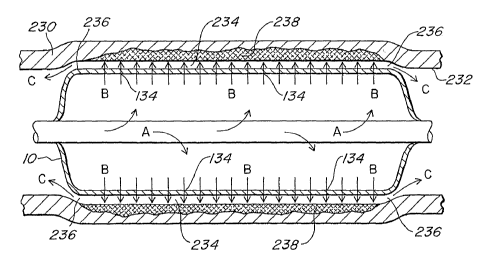
invention as illustrated in FIG. SC. The semi-confined space 234 is the area
between
the expandable device 10 as the expandable device 10 is pressed against the
internal wall
232 of the body lumen 230 and a pressurized fluid is forced out of the
expandable device
10. The semi-confined space 234 is bordered on one side by the expandable
device 10,
on an opposite side by the internal wall 232 of the body lumen, and on a third
side by a
22
CA 02526189 2005-11-17
WO 2004/105832 PCT/US2004/015992
small orifice 236 that forms around the edges of the expandable device 10
where the
expandable device ends as the pressurized fluid occupies the space.
To further elaborate, FIG. 5A shows the expandable device 10 inflated via the
fluid flowing in the direction of arrows A and pressed against the internal
wall 232 of the
body lumen 230. Tn the illustrated state, there is no semi-confined space 234
because the
fluid that is expanding the expandable device 10 has not yet passed through
the walls of
the expandable device 10. Once sufficient fluid has passed through the walls
of the
expandable device, the fluid remains pressurized and pushes against the
internal wall
232 and the outside wall of the expandable device 10 to form the semi-confined
space
234. Through compression of the expandable device 10 and the internal wall
232, the
semi-confined space 234 is created. FIG. 5B illustrates some fluid gathering
external to
the expandable device I O and beginning to form the semi-confined space 234
(however,
the space has not been completed as shown). Additional pressurized fluid
provided
external to the expandable device 10 expands the space to form the semi-
confined space
234 as shown in FIG. SC. Once complete, the semi-confined space 234 reaches
the end
of the expandable device 10 and the small orifice 236 is created. With
additional
pressurized fluid provided to the expandable device 10, the pressure external
to the
expandable device 10 is maintained, the semi-confined space 234 is maintained,
and the
small orifice 236 remains open. If the pressure of the fluid external to the
expandable
device falls substantially, then the small orifice 236 will close.
The semi-confined space 234 channels the pressurized fluid emitting through
the
through-pores I34 of the expandable device 10 in the direction of the arrows B
shown.
This arrangement causes the therapeutic agents andlor drugs concentrated in
the fluid to
have complete exposure to the targeted location of the internal wall 232. As
such, at
least some of the therapeutic agents and/or drugs permeate into the localized
cellular
space and tissue of the internal wall 232 into a permeation region 238. In
addition, some
of the fluid creates and then leaks out through the small orifice 236 around
the edges of
the expandable device 10 in the direction of arrows C. Thus, some of the
pressure from
within the expandable device 10 carries through to the semi-confined space
234,
23
CA 02526189 2005-11-17
WO 2004/105832 PCT/US2004/015992
resulting in the fluid being pressurized against the internal wall 232 of the
body lumen
230. Once the fluid exits the semi-confined space 234, the drugs and/or agents
contained within the fluid axe diluted and subsequently washed away.
The KIP effect is instrumental in creating the semi-confined space 234 between
the expandable device 10 and the internal wall 232 of the body lumen 230, and
thus
creating a more even distribution or deposition of therapeutic drug or agent
at the
permeation region 238 of the internal wall 232. This semi-confined space 234
is
continuously filled with fluid passing through the wall of the expandable
device 10 and
feeding into the semi-confined space 234. With the continuous fluid movement,
and the
elevated pressure within the semi-confined space 234, the actual structure of
the
expandable device 10 does not maintain contact with the internal wall 232 or
the
permeation region 238 for any extended period. Therefore, a continually
churning
volume of fluid containing a concentration of at least one therapeutic agent
or drug is
deposited at the internal wall 232. There is no opportunity for some axeas of
therapeutic
drug or agent to become stagnated in a location on the tissue of the internal
wall 232
because the fluid movement constantly churns the therapeutic drug or agent,
continually
providing a fresh supply and even or substantially uniform deposition.
The continuous churning and re-supply of the fluid containing the at least one
therapeutic drug or agent provides a regulated, substantially uniform,
therapeutic drug or
agent concentration at the tissue. The pressurized fluid also provides for
atraumatic
delivery or deposition of the therapeutic drugs or agents. Further, there is
no structural
impediment to drug deposition, such as struts from a stmt, or areas of
compression by a
balloon against the internal wall 232, that may cause pooling of the fluid and
thus the
therapeutic drug or agent. With an even deposition of a substantially uniform
concentration of therapeutic agent or drug, there is an increased efficiency
in tissue
permeation, and a more even concentration of therapeutic drug or agent
permeating the
internal wall 232 of the body lumen 230.
24
CA 02526189 2005-11-17
WO 2004/105832 PCT/US2004/015992
The delivery of a therapeutic agent or drug must achieve sufficient
concentration
at the targeted location for efficacy. Prior methods required use of a
substantially higher
dosemetric or volumetric amount of drug or agent to attempt to achieve a
therapeutic
effect at the targeted location relative to the present invention. Prior
methods had to
include sufficient amounts of a drug or agent to permeate the tissue while
also working
around structures such as stmt struts, and while being washed away from the
targeted
location. Alternatively, prior methods supplied a substantially greater amount
of drug to
a patient using a systemic approach rather than a targeted approach. However,
the
present invention provides an atraumatic method of increasing permeation of
tissue by at
least one therapeutic drug and/or agent using a pressurized fluid more
concentrated with
the therapeutic drug and/or agent for a more efficient and uniform
distribution of the
therapeutic drug and/or agent to the tissue of the targeted location.
FIGS. 6A, 6B, and 6C illustrate example embodiments of additional medical
devices that can be used in conjunction with the expandable device 10. FIG. 6A
is a
perspective illustration of a stmt 240 that is completely encapsulated in a
coating 242.
FIG. 6B is a perspective illustration of a stmt 244 with a partial coating
246. FIG. 6C
is a perspective illustration of a stmt 248 without a coating, or with a
coating on the
individual wires of the stent 248. The coating 242 and 246 can be made of PTFE
or
some other appropriate material as understood by one of ordinary skill in the
art.
Furthermore, the coating 242 can include one or more therapeutic agents or
components
for forming therapeutic agents as described herein. The expandable device 10
can be
placed within either of the stems 240, 246, or 248 to expand the stems 240,
246, and 248
against a lumen wall within a patient as understood by one of ordinary skill
in the art.
In an alternative arrangement, the expandable device 10 can expand within a
previously expanded stmt (such as stems 240, 246, and 248 of FIGS. 6A, 6B, and
6C).
In such an arrangement, the stmt 240, 246, or 248 will have already stretched
the body
lumen or cavity, likely to about 110% of its original inner diameter. The
expandable
device 10 then expands to meet and compress against the sent 240, 246, or 248
and body
lumen internal wall 232. Because the stmt 240, 246, or 248 adds additional
structure,
CA 02526189 2005-11-17
WO 2004/105832 PCT/US2004/015992
and the body tissue has already stretched, there is greater force pushing back
on the
expandable device 10, slightly compressing the expandable device I O more than
in the
previously described embodiment. In addition, an increased pressure can be
achieved in
the expandable device 10 up to about 6 atmospheres, versus the 3 to 4
atmospheres in
arrangements without stems 240, 246, or 24~.
As previously mentioned, the size and dimensions of the expandable device 10
are determined such that the expandable device 10 can expand to a sufficient
diameter
relative to the size of an application specific body lumen to create the semi-
confined
space 234. In other words, if the expandable device 10 is too small, the small
orifice 236
will be too large to maintain fluid pressure, and there will be no KIP effect.
If the
expandable device 10 is too large, the expansion of the expandable device 10
can cause a
rupture of the body lumen with application of a substantial pressure. Again,
there will
be no small orifice 236 unless there is pressurized fluid in the semi-confined
space
forcing its way out by creating the small orifice 236 with the slight
compression of both
the body lumen wall and the expandable device 10. The distance between the
body
lumen and the expandable device 10 (i.e., the height of the orifice) can range
between
about one ten-thousandth of an inch to about 2 mm. This distance between the
body
lumen and the expandable device 10 enables the atraumatic delivery of the
therapeutic
agent and/or drug to the targeted location. With the present invention, there
is no highly
pressurized jet of fluid ablating the tissue to increase permeation, nor is
there a hard
structure pressed against the tissue causing tissue damage. The distance
between the
body lumen and the expandable device 10, caused by the pressurized fluid,
protects the
tissue from damage.
It has unexpectedly been determined that this pressurized fluid allows the
therapeutic agents to preferentially distribute and penetrate into the
internal wall 232,
which results in a more efficient application of therapeutic drugs or agents
into both the
infra-cellular and extra-cellular space of the internal wall 232. The
resulting therapeutic
drug delivery effect) is the KIP effect. One result from the more efficient
application of
the therapeutic drugs or agents is that the dwell time required fox
application of a
26
CA 02526189 2005-11-17
WO 2004/105832 PCT/US2004/015992
specified dosage of therapeutic agent or drug to the targeted location is
reduced relative
to the previously referenced conventional methods. In addition, if the dwell
time is
maintained and not reduced, an increased amount of drug or agent permeates the
tissue
of the targeted location, thus having an improved therapeutic effect relative
to prior
methods.
Another result is that any fluid containing any therapeutic drugs or agents
that do
not permeate into the permeation region 238 of the internal wall 232 exits out
from the
semi-confined space 234 and the fluid pressure decreases to the ambient
pressure within
the body lumen 230, thereby having no localized drug delivery effect beyond
where the
KIP effect is applied.
In addition, in arrangements involving a stmt 240, 246, or 248 in combination
with the expandable device 10, as mentioned previously, a relatively higher
pressure is
obtained within the expandable device 10 (e.g., up to about 6 atmospheres).
The
increased pressure results in even further enhancement of therapeutic agent
distribution
and permeation into the tissue of the body lumen or cavity.
Therapeutic agents applied to the taxgeted location of the internal wall 232
over
time permeate the tissue of the internal wall 232. As described, fluid
containing
therapeutic agents that do not permeate the internal wall 232 exits the semi-
confined
space 234 and is diluted and flushed away into the general systemic blood
circulation.
The fluid applied to the targeted location using the KIP effect can be
relatively
concentrated with therapeutic agent or drug, with a smaller dosemetric or
overall
volumetric amount, because of the ability to expose the targeted location to a
stream of
fluid containing the therapeutic drug and/or agent over a period of time.
Therefore,
therapeutic agents that do not permeate the body tissue can escape to other
portions of
the patient's body without ill effect, because of the substantially diluted
state of the fluid
delivering the agents.
27
CA 02526189 2005-11-17
WO 2004/105832 PCT/US2004/015992
FIG. 7 illustrates one example method fox applying a therapeutic drug in
accordance with the present invention. The method includes positioning a drug
delivery
structure, such as the expandable device 10, within a patient's body at a
targeted location
such as the body lumen 230 (step 300). A first agent or component containing
an agent
is introduced to the drug delivery structure to react with a second agent or
component
containing an agent that is disposed within the delivery structure to form the
therapeutic
drug (step 302}. The therapeutic drug then emits from a plurality of locations
along the
drug delivery structure to the targeted location within the patient at a
controlled rate (step
304). If the expandable device 10 is sufficiently sized, and the pressure
provided to the
expandable device is appropriate, the therapeutic drug can emit using the KIP
effect for
improved distribution to the tissue and permeation in a reduced dwell time.
FIG. 8 illustrates an example embodiment of forming a polymeric body within a
patient. The method includes positioning a delivery structure, such as the
expandable
device 10, within the patient at the targeted location (step 320). A first
component is
introduced to the delivery structure to react with a second component disposed
within
the delivery structure to form a compound (step 322). The compound emits from
a
plurality of locations along the delivery structure at a predetermined
controlled rate for
application to a targeted location to form the polymeric body (step 324). If
the
expandable device 10 is sufficiently sized, and the pressure provided to the
expandable
device is appropriate, the therapeutic drug can emit using the KIP effect for
improved
distribution to the tissue and permeation in a reduced dwell time.
FIG. 9 illustrates an example embodiment of applying a therapeutic gas to a
targeted location within a patient's body. A gas delivery structure, such as
the
expandable device 10, is positioned at the targeted location (step 330). The
gas delivery
structure receives a first gas to react with a second gas disposed within the
delivery
structure to form the therapeutic gas (step 332). The therapeutic case is
emitted from a
plurality of locations along the gas delivery structure at a predetermined
controlled rate
for application to the targeted location (step 334). If the expandable device
10 is
sufficiently sized, and the pressure provided to the expandable device is
appropriate, the
28
CA 02526189 2005-11-17
WO 2004/105832 PCT/US2004/015992
therapeutic drug can emit using the KIP effect for improved tissue permeation
in a
reduced dwell time.
In each of the embodiments illustrated in FIGS. 7, 8, and 9, methods discuss a
S second gas or component being disposed within the delivery structure. It
should be
noted that the gas or component can exist in the delivery structure in a
number of
different ways. For example, the second gas or component can be supplied to
the
delivery structure just prior to, or coincident with, the introduction of the
first gas or
component to the delivery structure. Alternatively, the second gas or
component can be
sealed within the delivery structure prior to use by the clinical user. In
still another
alternative, the component or gas can be resident within the delivery device
structure,
such as being incorporated into, e.g., PTFE material or other delivery device
material, or
applied as a coating to the walls of the delivery device structure.
The present invention KIP effect provides for the atraumatic delivery of at
least
one therapeutic drug and/or agent contained within a pressurized fluid in a
substantially
uniform drug or agent concentration. More specifically, the present invention
KIP effect
provides an atraumatic method of increasing permeation of tissue by at least
one
therapeutic drug and/or agent using a pressurized fluid more concentrated with
the
therapeutic drug and/or agent for a more efficient and uniform distribution of
the
therapeutic drug and/or agent to the tissue of the targeted location relative
to prior
methods. Because of the more efficient drug or agent distribution, the dwell
time
required for application of a specified dosage of therapeutic agent or drug to
the targeted
location is reduced relative to prior methods for delivery of a specified
dosage of drug or
agent. In addition, any fluid containing any therapeutic drugs or agents that
do not
permeate the body tissue exits out from the semi-confined space. Upon exit,
the fluid
pressure decreases to the ambient pressure within the body lumen, the drug or
agent fluid
concentration is diluted and washed away. Therefore, there is no localized
drug delivery
effect beyond where the KIP effect is applied.
29
CA 02526189 2005-11-17
WO 2004/105832 PCT/US2004/015992
Numerous modifications and alternative embodiments of the present invention
will be apparent to those skilled in the art in view of the foregoing
description.
Accordingly, this description is to be construed as illustrative only and is
for the purpose
of teaching those skilled in the art the best mode for carrying out the
present invention.
Details of the structure may vary substantially without departing from the
spirit of the
invention, and exclusive use of all modifications that come within the scope
of the
disclosed invention is reserved.