Note: Descriptions are shown in the official language in which they were submitted.
CA 02526231 2005-10-24
WO 2005/103793 PCT/CA2004/001995
- 1 -
A Micro-Electro-Mechanical-System Two Dimensional Mirror with
Articulated Suspension Structures for High Fill Factor Arrays
Field of the Invention
The invention relates to a MEMS (micro-electro-
mechanical-system) two dimensional mirror with articulated
suspension structures for high fill factor arrays.
Background of the Invention
A MEMS (Micro-Electro-Mechanical-System) device is a '
micro-sized mechanical structure having electrical circuitry
fabricated together with the device by various microfabrication
processes mostly derived from integrated circuit fabrication
methods. The developments in the field of
microelectromechanical systems (MEMS) allow for the bulk
production of microelectromechanical mirrors and mirror arrays
that can be used in all-optical cross connect switches, lxN,
NxN optical switches, attenuators etc. A number of
microelectromechanical mirror arrays have already been built
using MEMS production processes and techniques. These arrays
have designs that fall into approximately three design
categories.
A first category consists of conventional 2D gimbal
mirrors with each mirror surrounded by a frame. The
conventional 2D gimbal mirror is one of the most common types
of MEMS 2D micromirrors. An example is shown in Figure 6. It
consists of a central mirror 10 that is connected to an outer
frame 12 with torsional hinges 14. The outer frame 12 is in
turn connected to the support structure 16 with another set of
torsional hinges 18. There are four electrodes under the
central mirror 10 that can be actuated resulting in a 2D tilt
of the mirror-.frame assembly. One such device is disclosed
under US Patent Application Publication No: US2002/0071169 A1,
CA 02526231 2005-10-24
WO 2005/103793 PCT/CA2004/001995
- 2 -
publication date June 13, 2002. One of the shortcomings of
this design is the inability to achieve high fill factors (that
is the spacing between two consecutive mirrors or the ratio of
the active area to the total area in an array) in a mirror
array. An example of a high fill factor would be >90% active
mirror portion along one dimension.
A second category consists of 2D/3D mirrors with
hidden hinge structures. With significant advances made in
Spatial Light Modulators, a number of 2D micromirror devices
have been designed with various types of hidden hinge
structure. Examples of these are disclosed in US Patent Number
5,535,047, US Patent Number 5,661,591, US Patent Number: US
6,480,320 B2.
A schematic of an example of such a device is shown
in Figure 7. Although this device structure can yield high
fill factor arrays, the fabrication processes are very complex.
For more discussion on the Spatial Light Modulators and Digital
Mirror devices with hidden hinge structure, references are made
to US Patent No 5,061,049, US Patent No 5,079,545, US Patent No
5,105,369, US Patent No 5,278,652, US Patent No 4,662,746, US
Patent No 4,710,732, US Patent No 4,956,619, US Patent No
5,172,262, and US Patent No 5,083,857.
A third category consists of 2D mirrors each mounted
' on a single moving flexible post. An example of a MEMS tilt
platform supported by a flexible post 30 as shown in Figure 8.
The post 30 extends within a moat 32 or trench formed in the
substrate or supporting material 34. The post 30 can be made
sufficiently long and flexible to act as an omnidirectional
hinge, bending to allow the mirror 36 to be positioned with two
degrees of freedom.
Some of the shortcomings of this design are process
complexity, post flexibility, wiring, and tilt eccentricity. A
CA 02526231 2005-10-24
WO 2005/103793 PCT/CA2004/001995
- 3 -
few of such devices have been disclosed in US Patent
No 5,469,302, US Patent Application Publication No US
2002/0075554 A1. Furthermore, the control for these devices
becomes complex and is a substantial part of the device cost.
Summary of the Invention
Some of the advantages realized in some but not
necessarily all embodiments include:
high fill factor linear arrays. Fill factors as high
as 99% may be achieved in some embodiments along one dimension;
almost negligible coupling between two tilt axes;
inexpensive and simple control. Even an open
loop/look up table control is a possibility;
simple fabrication process can be used to fabricate
the device; and
the cantilever part of the device can also be used
for capacitive, magnetic or optical sensing of mirror position.
According to one broad aspect, the invention provides
a micro-electro-mechanical-system (MEMS) mirror device,
comprising: a mirror having a 2-dimensional rotational
articulated hinge at a first end, and having a 1-dimensional
rotational articulated hinge at a second end opposite the first
end; a movable cantilever connected to the mirror through the
1-dimensional rotational articulated hinge; a support structure
connected to the mirror through the 2-dimensional rotational
articulated hinge and connected to the movable cantilever; a
rigid extension of the movable cantilever extending beyond
where the support structure is connected to the movable
CA 02526231 2005-10-24
WO 2005/103793 PCT/CA2004/001995
- 4 -
cantilever in a direction opposite to the mirror; whereby
movement of said movable cantilever causes rotation of the
mirror in a first axis of rotation, and the mirror is also
rotatable about a second torsional axis of rotation
perpendicular to said first axis of rotation; and whereby
movement of the extension of the movable cantilever causes a
corresponding opposite movement of the movable cantilever.
In some embodiments, the 2-dimensional rotational
articulated hinge comprises: a first 1-dimensional rotational
articulated hinge having a first mounting point at a first end
and having a second end; a second 1-dimensional rotational
articulated hinge having a second mounting point at a first end
and having a second end, the second end of the first 1-
dimensional rotational articulated hinge being connected to the
second end of the second 1-dimensional rotational articulated
hinge; a third 1-dimensional rotational articulated hinge
connected to the second ends of the first and second
articulated 1-dimensional rotational hinges; whereby the first
1-dimensional rotational articulated hinge and the second 1-
dimensional rotational articulated hinge define the first axis
of rotation between the first and second mounting points, and
the third 1-dimensional rotational articulated hinge and the 1-
dimensional rotational articulated hinge at the second end of
the mirror define the second torsional axis of rotation
perpendicular to the first axis of rotation.
In some embodiments, each 1-dimensional rotational
articulated hinge comprises a respective articulated beam
having a large thickness to width aspect ratio.
In some embodiments, each 1-dimensional rotational
articulated hinge comprises a respective articulated beam
having a large thickness to width aspect ratio, the beam being
formed of a material or materials selected from a group
CA 02526231 2005-10-24
WO 2005/103793 PCT/CA2004/001995
- 5 -
consisting of silicon, polysilicon, Silicon Nitride, Silicon
dioxide, and metallic depositable materials.
In some embodiments, the beams are formed of a
unitary construction.
In some embodiments, the beams the mirror, and the
movable cantilever are formed of a unitary construction.
In some embodiments, a device in which the mirror has
an angular range of motion at least 0.3 degrees in each axes.
In some embodiments, a device further comprises
electrodes for applying electrostatic force to the mirror so as
to move the mirror in the first and second axes of rotation.
In some embodiments, the electrodes comprise two
electrodes each for applying'a respective electrostatic force
to the mirror so as to move the mirror in a respective
direction in the second axis of rotation, and at least one
electrode for applying electrostatic force to the movable
cantilever so as to move the mirror in the first rotational
axis.
In some embodiments, said at least one electrode
comprises two electrodes mounted on the support structure each
for applying a respective electrostatic force to the moving
cantilever so as to move the mirror in a respective direction
in the first rotational axis.
In some embodiments, said support structure comprises
a first region on a first side of the movable cantilever to
which is mounted a first of said two electrodes for applying
electrostatic force to the movable cantilever, and a second
region opposite the moving cantilever to the first region to
which is mounted a second of said two electrodes for applying
electrostatic force to the movable cantilever.
CA 02526231 2005-10-24
WO 2005/103793 PCT/CA2004/001995
- 6 -
In some embodiments, a device comprises a first
electrode for applying electrostatic force to the mirror so as
to move the mirror in a first direction in the first axis of
rotation, and a second electrode for applying electrostatic
force to the mirror so as to move the mirror in a second
direction in the first axis of rotation.
In some embodiments, the first electrode for applying
electrostatic force to the mirror so as to move the mirror in a
first direction in the first axis of rotation is on the support
structure proximal the moving cantilever, and the second
electrode for applying electrostatic force to the mirror so as
to move the mirror in a second direction in the first axis of
rotation is on the support structure proximal the extension of
the moving cantilever.
In some embodiments, the moving cantilever and the
rigid extension of the moving cantilever are together pivotably
mounted to the support structure.
In some embodiments, the moving cantilever and the
rigid extension of the moving cantilever are together rigidly
mounted to a portion of the support structure which is
sufficiently flexible to allow the moving cantilever and the
rigid extension of the moving cantilever to rotate in the first
axis of rotation.
In some embodiments, moments of inertia of the rigid
extension of the moving cantilever substantially balance
moments of inertia of the moving cantilever and mirror.
rn some embodiments, a device in which the mirror is
made of silicon plated with a metal.
In some embodiments, the metal comprises Au, A1 or Cu
layers.
CA 02526231 2005-10-24
WO 2005/103793 PCT/CA2004/001995
In some embodiments, a plurality N of devices
arranged side by side to form a 1xN MEMs array, where N>_2.
In some embodiments, a plurality NxM of devices
arranged in N rows of M devices thereby forming an NxM MEMs
array, where N>_2 and M>_2.
In some embodiments, the mirror is used for optical
switching.
In some embodiments, the movable cantilever is used
for capacitive, magnetic or optical sensing of mirror position.
l0 Brief Description of the Drawings,
Preferred embodiments of the invention will now be
described with reference to the attached drawings in which:
Figure 1A and Figure 1B provide two views of a
conventional 1 dimensional MEMS mirror with an articulated
suspension structure;
Figure 2 shows the device of Figure 1 in two
rotational states;
Figure 3A is a plan view of a two dimensional
articulated rotational hinge provided by an embodiment of the
invention;
Figure 3B illustrates a MEMS mirror featuring the two
dimensional rotational articulated hinge of Figure 3A;
Figure 4A is a view of a mirror with a two
dimensional rotational articulated hinge and moving cantilever
mounting system provided by an embodiment of the invention;
Figures 4B and 4C provide a cutaway and side
sectional view of a mirror with a two dimensional rotational
CA 02526231 2005-10-24
WO 2005/103793 PCT/CA2004/001995
_ g _
articulated hinge and moving cantilever mounting system
provided by another embodiment of the invention;
Figure 4D is a view of a mirror with a two
dimensional rotational articulated hinge and moving cantilever
mounting system provided by another embodiment of the
invention;
Figure 5 is a one dimensional MEMS array of devices
like the device of Figure 4A;
Figure 6 is a view of a conventional two dimensional
gimbal mirror with a supporting frame;
Figure 7 is a representative sketch of a MEMS mirror
with a hidden hinge structure; and
Figure 8 is a representative sketch of a 2D mirror
mounted on a single moving flexible post.
Detailed Description of the Preferred Embodiments
A known 1D MEMS torsional mirror supported by
articulated suspension springs/hinges is shown in Figures 1A
and 1B. This arrangement consists of a support structure 30
within which is mounted a mirror 34 connected to the support
structure 30 through two articulated hinges 36. Typically, the
entire mirror plus articulated hinges arrangement is made of a
single piece of silicon. The articulated hinges 36 consist of
a silicon beam with a high aspect ratio of length to width
thereby allowing torsional rotation. Using articulation allows
a long silicon beam to be provided in a very small space. Also
shown are a pair of address electrodes 38 and 40. These would
be connected to control systems capable of applying voltages to
the electrode. Typically the mirror arrangement would be
attached to ground. The mirror 34 can be rotated around its
rotational axis (~x) 32 by applying electrostatic force on
CA 02526231 2005-10-24
WO 2005/103793 PCT/CA2004/001995
- 9 -
either side of the mirror using the electrodes 38,40. This is
shown in Figure 2. Generally indicated at 50 is the mirror in
a first configuration where the mirror has been rotated counter
clockwise about the rotational axis 32 and generally indicated
at 52 shows the same arrangement in which the mirror has~been
rotated clockwise about the rotational axis 32.
To facilitate 2D rotation of a mirror, that is
rotation in both (0x) and (8z), 8z being orthogonal to the main
torsional tilt (~x), an embodiment of the invention provides a
2D rotatable articulated hinge. A top view of a new
articulated hinge is shown in Figure 3A. The 2D rotatable
articulated hinge includes a first articulated hinge portion 60
and a pair of second articulated hinges 62,63. Each of the
second articulated hinges 62,63 is connectable to a support
structure indicated generally at 64 and is also connected to
the first articulated hinge 60. Each of the three articulated
hinges 60,62,63 is similar to the conventional articulated
hinge 36 of Figure lA. Namely each articulated hinge consists
of a silicon beam with high aspect ratio thickness to width.
The entire arrangement consisting of the three articulated
hinges 60,62,63 is preferably made from a single unitary piece
of silicon. In other embodiments, the arrangement is made of a
deposited material such as polysilicon, Silicon Nitride,
Silicon dioxide, and Metallic depositable materials. Other
materials may be employed. Preferably the construction is
unitary in the sense that no assembly is required. However,
the beams may be made of multiple materials, for example in a
s
layered structure. The first articulated hinge 60 allows
rotation along a first torsional axis (8x) while each of the
second articulated hinges 62 and 63 allow rotation about a
second axis (Az) .
CA 02526231 2005-10-24
WO 2005/103793 PCT/CA2004/001995
- 10 -
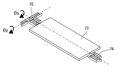
Referring now to Figure 3B, shown is a first example
use of the articulated hinge of Figure 3A. Here the
articulated hinge is generally indicated by 70 and is connected
to a mirror 72 at the opposite end of which there is another 1D
articulated hinge 74. Preferably the entire arrangement of
Figure 3B is made from a single piece of silicon. The
arrangement as shown in Figure 3B allows the mirror 72 to
rotate about the main rotational axis (8x) and the additional
rotational axis (8z) which is orthogonal to the main rotational
axis.
In a preferred embodiment of the invention, the
arrangement of Figure 3B is employed in an apparatus
illustrated by way of example in Figure 4A. Here, again the 2D
rotation articulated hinge 70 is shown connected to the mirror
72 and 1D rotational articulated hinge 74. A support structure
is generally indicated by 76. The 2D rotational articulated
hinge 70 is connected in two places 78,79 to the support
structure. The 1D rotational articulated hinge 74 is connected
to the support structure 76 through a cantilever 80. The
cantilever is preferably simply another piece of silicon which
is connected to the support structure 76 at 82 in a manner
which allows substantially no rotation of this cantilever about
the main rotational axis (Ax). However, the cantilever 80 does
have some flexibility, and in particular, the end 87 of the
cantilever 80 most remote from the connection 82 to the support
structure is capable of some up and down motion. To allow
additional flexibility of the cantilever 80, parts may be
removed. In the illustrated example, the cantilever 80
includes a gap 89 near the mounting point 82 to support
structure 76. This reduces the amount of force necessary to
cause the up and down motion of point 87.
CA 02526231 2005-10-24
WO 2005/103793 PCT/CA2004/001995
- 11 -
To control rotation in the torsional axis (~x),
,electrodes are provided 84,85 which operate similar to the
electrodes through 38,40 of Figure lA. This allows the control
of the rotation of the mirror 72 about the main torsional axis.
Also shown is an electrode 86 beneath the cantilever structure
80 which controls the up and down motion of the end 87 of the
cantilever 80 most remote from the connection 82 to the support
structure 76. The up and down motion of this point 87 causes
rotation of the mirror 72 about the additional rotational axis
(9z), thus making the mirror tilt in both axes either
simultaneously or independently.
Any suitable dimensions for the articulated hinges
may be employed. Different numbers of articulations can be
employed. The more articulations included in a given
articulated hinge, the less will be the required force to cause
rotation about the respective axis. In an example
implementation, the dimensions of the various hinges are as
follows
Hinge 62 and 63 : ~ 75 um (L) , 1. 5 um (W) , 15 um
(T) , 5 um (Gap) and 3 (articulations) ;
Hinge 60 and 74: ~75 um (L) , 1.5 um (W) , 15 um
(T), 5 um (Gap) and 11 (articulations)}
In preferred embodiments, both for the embodiment of
Figure 4A and subsequently described embodiments, some or all
of the entire structure used to make the mirror, cantilevers
and articulated hinges is connected to ground, and behaves like
an electrode. For example if these components are made of
doped silicon they become conductive. In this way, by applying
a voltage to an electrode (for example electrode 84 of Figure
4A) the mirror behaves as the second electrode without the need
to deposit a second designated electrode.
CA 02526231 2005-10-24
WO 2005/103793 PCT/CA2004/001995
- 12 -
In some embodiments, in order to provide the most
flexible control over the rotation over the additional
rotational axis (8z), an additional support structure is
provided on top of the cantilever 80 with an additional
electrode so that a force could be applied to cause the end of
87 of the cantilever 80 to move upwards. However, in some
applications, this additional degree of freedom may not be
required. An example of this is shown in Figure 4B (and the
side view in figure 4C) which is very similar to Figure 4A,
with the exception of the additional support structure 91 and
additional electrode 93 which allow an electrostatic force to
be applied to the cantilever structure to move it both up and
down. Note the view of Figure 4B only shows half of the
structure.
The embodiment of Figure 4A has employed the use of
electrodes through which electrostatic forces can be applied to
control rotation in the two rotational axes. More generally,
any other type of force could also be employed in either or
both of these rotational axes. For example thermal, magnetic,
thermal bimorph or piezo-electric forces can be employed to
achieve the required rotation and control.
This combination of the 2D rotational articulated
hinge, an articulated torsional mirror, and a moving cantilever
results in a fully functional 2-D MEMS mirror. The cantilever
can be deflected in either up or down directions depending on
the arrangement of electrodes or force application, thus making
the torsional mirror rotate about the second axis ~z in either
direction. For most electrostatic applications, the cantilever
can be deflected downwards only to reduce the number of I/O's
and control complexity.
A number of mirrors can be placed side by side to
make a linear mirror array with minimal spacing between two
CA 02526231 2005-10-24
WO 2005/103793 PCT/CA2004/001995
- 13 -
mirrors. An example of this is shown in Figure 5 where a
linear array of four 2D torsional mirrors 90,92,94,96 with 2D
rotational articulated hinges and cantilevers is shown. An
arbitrary number could be included in such an array. Another
embodiment provides a two dimensional array of NxM such mirror
devices.
One of the main advantages of the structure of Figure
4A is the minimal coupling between the two tilt axes. This
device structure can be used in any number of applications. It
can be used as a single mirror for any appropriate application
of a single or multi-array configuration. The arrangement
achieves a high fill factor for mirror arrays (that is the
spacing between two consecutive mirrors in an array is
minimized) and is very simple to fabricate. The spacing
between two mirrors can be as low as few microns or as limited
by microfabrication processes.
Another embodiment of the invention will now be
described with reference to Figure 4D. This embodiment is very
similar to that of Figure 4A. This embodiment includes an
additional cantilever 97 mounted over further support structure
98 to which an additional electrode 99 is affixed. Cantilever
structures 80 and 97 together pivot about mounting points to
the support structure 76. In operation, with this arrangement
an electrostatic force can be applied between the electrode 87
and cantilever 80 to move point 87 in a downward direction.
Similarly, an electrostatic force can be applied between
electrode 99 and the underside of cantilever 97 to cause the
end 87 of cantilever 80 to move upwards. Thus, the arrangement
of Figure 4D provides the same flexibility as the arrangement
of Figure 4B provided earlier in that both upwards and
downwards mobility in the second axis of rotation (8z) is
possible. The attachment of the cantilever structure composed
of combined elements 80 and 97 to the support structure can
CA 02526231 2005-10-24
WO 2005/103793 PCT/CA2004/001995
- 14 -
either be pivotable, or rigid. In the event of a rigid
connection, the support structure 76 would need to have some
flexibility to allow the upwards and downwards motion of the
two cantilever portions on either side of support structure 76.
In another embodiment, the arrangement of Figure 4D
is implemented with a balanced cantilever structure. With this
embodiment, the moments of inertia on either side of the
support structure 76 are substantially~equalized. In one
embodiment, this is achieved by making the second cantilever
portion 97 substantially longer than the cantilever portion 80
such that the moments of inertia of the second cantilever
portion 97 about the support structure 76 offsets the moment of
inertia of the components on the other side of the support
structure.
The device can be fabricated with existing MEMS
fabrication processes. A few of the suitable processes that are
commercially available are "Optical IMEMS"R from Analog Devices
Inc (see Thor Juneau, et al, 2003, 'Single-Chip 1x84 MEMS
Mirror Array For Optical Telecommunication Applications',
Proceeding of SPIE, MOEMS and Miniaturized Systems III, 27-29
January 2003, Vol. 4983, pp. 53-64.), SOI MUMPS
(http://www.memsrus.com/figs/soimumps.pdf) from Cronos (MEMScAP
subsidiary). A custom process can also be put together to
fabricate the device.
It is to be understood that in a system application,
a control system would be provided to control the rotation of
the mirror in the two degrees of freedom. This would be
controlled through the proper application of the forces through
the various electrodes. The control system will preferably be
an open loop system with a voltage look-up table for various
tilt position or a closed loop system with capacitance or
optical sensing.
CA 02526231 2005-10-24
WO 2005/103793 PCT/CA2004/001995
- 15 -
The mirrors in the above employed embodiments need to
have a reflective coating, for example of Au, A1, or Cu in one
of more layers. The mirrors are used to perform the main
switching of beams of light. However, it is to be understood
that the cantilever portion could also have a reflective
coating. The cantilever and/or mirror components could be used
for capacitive or optical sensing. For example, the mirror
components might be used for switching, while the cantilever
components are used to perform sensing with signals generated
to perform feedback control over the orientation of the mirrors
in the additional rotational axis (Az).
Numerous modifications and variations of the present
invention are possible in light of the above teachings. It is
therefore to be understood that within the scope of the
appended claims, the invention may be practiced otherwise than
as specifically described herein.