Note: Descriptions are shown in the official language in which they were submitted.
CA 02526740 2011-03-25
1
PROTECTION AGAINST LANDMINE EXPLOSION
Field of the Invention
This invention relates to a method of protecting a body or hull and any
occupant of a land vehicle, such as an armoured vehicle, e.g. an armoured tank
or car, against the effects of a landmine explosion, e.g. an anti-tank
landmine
explosion. It relates also to a land vehicle, and to a combination of a ground
engaging element for a land vehicle and a shock wave guide member.
Background of the Invention
When a vehicle sets off a landmine, generally the Iandmine explodes
underneath a ground engaging element such as a wheel or track of the vehicle
because of the ground pressure created by said ground engaging element on
the landmine.
Japanese Patent document having a publication number 2002090095,
discloses an apparatus for removing a mind buried under the ground surface.
The apparatus includes a composite rotor having a plurality of generally
coaxial
rollers loosely located with lost motion in a radial direction over a fixed
axis shaft
mounted on, so as spatially to lead, a vehicle. The rollers can individually
follow
contours, hollows, humps, etc. to trigger landmines. Behind the rotor there is
provided a protective plate screening the landmine blast and protecting the
vehicle and an occupant.
Japanese Patent document having a publication number 2002340499,
discloses a rotor including a plurality of blades. The rotor is rotated to
cause the
blades to cut into a ground surface to destroy mines. A curved safety cover is
provided over the rotor to protect the vehicle and a driver from sand, mud and
landmine fragments. A low level grader-like blade deflects sand, mud and mine
fragments laterally to provide a smooth running surface for the vehicle. It is
notable that the vehicle is not intended to trigger landmines to explode, but
to
destroy Iandmines before explosion. The inventor thus did not anticipate
landmine explosions and resulting shock waves.
CA 02526740 2011-03-25
2
United States Patent 5442990 discloses a scarifying drum leading a track
vehicle to explode Iandmines. A flap is provided over the drum to act as a
shield.
Summary of the Invention
Accordingly, it is an object of this invention to at least partially overcome
some of the disadvantages of the prior art.
In accordance with a first aspect of the invention, there is provided a
method of protecting a body or hull and any occupant of a land vehicle movable
along a substrate on ground engaging elements against the effects of a
landmine explosion, including conducting shock waves generated by the
landmine explosion laterally outwardly by means of a shock wave guide member
of a material having a relatively high acoustic speed and located proximate a
ground engaging element of the vehicle.
For purposes of this specification, terms denoting direction, such as fore,
rear, lateral, and the like should be interpreted with reference to a normal
direction of forward travel of a land vehicle. The term"laterally
outward"means
"sideways away from (the land vehicle)".
By"relatively high"acoustic speed is meant an acoustic speed higher than
the acoustic speed of the metal used in components of the land vehicle. Such
metal, e.g. steel, aluminum, and alloys thereof, generally have an acoustic
speed
of about 5000 m/sec.
The material of each shock wave guide member may be selected from
materials including glass, a suitable ceramic such as an alumina, or the like,
which have an acoustic speed of higher than about 6000 m/sec. Some ceramics
may have acoustic speeds up to about 8000 m/sec.
When the vehicle is a track vehicle, the ground engaging elements being
in the form of tracks, the guide member may be located in at least one of a
well
of a bogey wheel, i. e. an annular cavity surrounding a hub and radially
inward of
a rim of the bogey wheel ; and immediately above a bottom run of a track
intermediate bogey wheels.
CA 02526740 2011-03-25
3
When the vehicle is a wheeled vehicle, the ground engaging elements
being in the form of wheels, the guide member may be located in a well of at
least one of the wheels. The method may include absorbing energy by means of
a liquid provided in a tyre of the vehicle, in the case that the wheels have
tyres.
In accordance with a second aspect of the invention, there is provided a
land vehicle movable along a substrate on ground engaging elements, which
land vehicle is adapted or converted to protect its body or hull and any
occupant
against the effects of a landmine explosion, the land vehicle comprising a
plurality of shock wave guide members proximate ground engaging elements
thereof, the shock wave guide members being oriented to conduct shock waves
laterally outwardly away from the body or hull.
When the land vehicle is in the form of a track vehicle, the ground
engaging elements being in the form of tracks, the guide members may be
positioned in wells of bogey wheels, as well as immediately above a bottom run
of each track intermediate bogey wheels. Those guide members proximate
tracks intermediate bogey wheels may have layers of low friction material,
such
as TEFLON, on their surfaces interfacing with the tracks.
When the land vehicle is in the form of a wheeled vehicle, the ground
engaging elements being in the form of wheels, the guide members may be
positioned annularly in wells of at least some of the wheels e. g. at least
fore
wheels. When the wheels have hollow tyres around wheel rims, the guide
members may be positioned annularly in the hollows of the tyres. By way of
development, cavities within the tyres may be filled with a liquid for
absorbing
some of the energy of the explosion. The liquid may be selected to have an
appropriate boiling point and coefficient of latent heat of evaporation. It
may, for
example, be water, glycerin, a mixture of water and glycerin, or the like.
The guide members may be of composite construction, each guide
member comprising a plurality of oriented or directed laminates of a material
having an acoustic speed of at least about 6000 m/sec. Such material may be a
primary material, e. g. a glass or ceramic material. The guide member may be
in
laminated form comprising laminates of the primary material interposed by an
interface material having an acoustic speed lower than that of steel, the
CA 02526740 2011-03-25
4
laminates being directed generally in said laterally outward and upward,
oblique
direction. The interface material may be a synthetic polymeric material. Said
interface material may have an acoustic speed lower than that of air. The
laminates may thus be sandwiched in-between layers of material having a
relatively low acoustic speed, lower than about 1000 m/sec, even lower than
the
acoustic speed of air.
The laminates may be oriented to extend obliquely laterally outwardly in
use.
A respective guide member may be positioned annularly inward of a tread
of the wheel. It may be annularly around a hub of the wheel. It is preferably
acoustically well coupled to a wheel frame (colloquially referred to as a
wheel
rim).
The guide members may have surfaces which are profiled snugly to be
received with little clearance, or even slight touching, on surfaces of the
ground
engaging elements.
In accordance with a third aspect of the invention, there is provided the
combination of a ground engaging element for a land vehicle and a shock wave
guide member of a material having an acoustic speed of higher than about 6000
m/sec, the guide member being locatable proximate a ground engaging surface
of the ground engaging element.
When the ground engaging element is a track and bogey wheel
arrangement for a track vehicle, the guide member may be adapted for location
in one of a well of a bogey wheel, and immediately above a lower run of the
track
intermediate bogey wheels.
When the ground engaging element is a wheel for a wheeled vehicle, the
guide member may be adapted for location within a well of the wheel.
When the ground engaging element is a wheel, having a hollow tyre, for a
wheeled vehicle, the guide member may be adapted for location within the
hollow of the tyre.
In another aspect, the present invention resides in a method of protecting
a body or hull and any occupant of a land vehicle movable along a substrate on
CA 02526740 2011-03-25
ground engaging elements against the effects of a landmine explosion,
including
conducting shock waves generated by the landmine explosion laterally outwardly
by means of a shock wave guide member comprising a plurality of oriented
laminates of a material having a relatively high acoustic speed and located
5 proximate a ground engaging element of the vehicle, the laminates being
oriented to extend laterally outwardly.
In a further aspect, the present invention resides in a land vehicle movable
along a substrate on ground engaging elements, which land vehicle is adapted
or
converted to protect its body or hull and any occupant against the effects of
a
landmine explosion, the land vehicle comprising a plurality of shock wave
guide
members proximate ground engaging elements of the land vehicle, characterized
in that the shock wave guide members are of a material having a relatively
high
acoustic speed higher than the acoustic speed of metal used in components of
the land vehicle which components have an acoustic speed generally of about
5000 rn/sec, the shock wave guide members comprising a plurality of laminates
oriented to conduct shock waves laterally outwardly away from the body or
hull.
In yet another aspect, the present invention resides in a ground engaging
element for a land vehicle in combination with a shock wave guide member of a
material having an acoustic speed of higher than about 6000 m/sec, the guide
member being locatable proximate a ground engaging surface of the ground
engaging element and comprising a plurality of laminates oriented to conduct
shock waves laterally outwardly in use.
Further aspects of the invention will become apparent upon reading the
following detailed description of the drawings, which illustrate the invention
and
preferred embodiments of the invention.
Brief Description of the Drawings
The invention is now described by way of examples with reference to the
accompanying diagrammatic drawings. In the drawings
Figure 1 shows, in fragmentary side view, a track vehicle converted in
accordance with the invention;
CA 02526740 2011-03-25
5a
Figure 2 shows, to a larger scale, fragmentarily, a bogey wheel of the
track vehicle of Figure 1, converted in accordance with the invention;
Figure 3 shows, in diametrical section, the bogey wheel of Figure 2;
Figure 4 shows, in cross section, to a larger scale, a guide member
proximate a track of the track vehicle of Figure 1;
Figure 5 shows, fragmentarily, in radial section, a first embodiment of a
wheel for a wheeled vehicle in accordance with the invention; and
Figure 6 shows, in a view corresponding to that of Figure 5, a second
embodiment of a wheel for a wheeled vehicle.
Detailed Description of the Preferred Embodiments
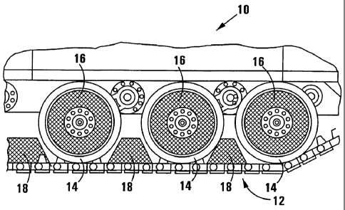
With reference to Figures 1 to 4 of the drawings, a track vehicle in the
form of an armoured tank is generally indicated by reference numeral 10. The
track vehicle 10 has a pair of tracks 12 guided along a lower run of each
track on
bogey wheels 14. The track is shown fragmentarily only, and only one track 12
is
shown, also fragmentarily.
In accordance with the invention, a first kind of guide member, generally
indicated by reference numeral 16, is located within wells of the bogey wheels
14, i. e. annularly intermediate hubs 14.1 and rims 14.2 of the respective
bogey
wheels 14.
In the event that the bogey wheel 14 has webs 14.3 at circumferentially
spaced positions within said wells, the guide member 16 is in the form of a
composite guide member comprising a plurality of segments 16.1 shown in
Figure 2.
As can best be seen in Figure 3, each segment has a plurality of
laminates 16.2 sandwiched in-between dividing layers 16.3 which may be of a
CA 02526740 2005-11-23
WO 2004/106840 PCT/IB2004/001717
6
yielding, even resilient, low acoustic speed material such as polyurethane,
rubber
or the like. The laminates 16.2 are oriented laterally outwardly.
In the event of a landmine explosion underneath the bogey wheel
14, shock waves generated by the landmine explosion will propagate through the
track 12, through the rim 14.2 of the bogey wheel 14 immediately above the
track
12 and will be "loaded into" the respective segment or segments 16.1. The
Applicant has realized that shock waves encounter resistance to propagation
inversely proportional to the acoustic speed of a material. Thus, in a
material
having a high acoustic speed like glass, especially ceramics, such as that of
the
guide member 16, the shock waves are guided effectively laterally outwardly in
accordance with the orientation of the laminates. It is further to be
appreciated
that, should a component of the shock waves be conducted obliquely along such
a laminate, when it reaches a dividing layer 16.3 having a low acoustic speed
and thus offering high resistance to propagation of shock waves, the shock
waves are deflected back into the high acoustic speed material which assists
in
guiding the shock waves laterally outwardly.
When the shock waves reach the surface of the guide member, and
preferably it should do so at approximately right angles, the shock waves,
when
they encounter the neighbouring air, which has a low acoustic speed, cause
spalling of the material which results in a fragment or fragments of material
to be
liberated and to be projected generally in the direction of spalling i.e.
laterally
outwardly.
In this regard, the Applicant has realized that a blast effect
generated by the landmine explosion and following the shock waves in time,
generally follows the path or route of least resistance. In this regard, the
Applicant has further appreciated that the shock waves crack and pulverize the
material of the guide member, but at a propagation speed substantially lower
than the acoustic speed. Thus, the guide member remains intact fully to
CA 02526740 2005-11-23
WO 2004/106840 PCT/IB2004/001717
7
propagate the shock waves, but immediately behind the shock waves, cracks
and pulverizes to facilitate being displaced or blown away by the blast
effect.
Thus, a route of lesser resistance is created in the direction in which the
shock
waves were guided. Furthermore, the effect of spalling and of a fragment being
projected from the outer surface creates a region of low pressure which is
followed by the blast effect.
Thus, the Applicant has realized that managing or guiding of the
shock waves in a predetermined direction away from a body of the track vehicle
not only protects the body against the effect of the shock waves, but also
that the
blast effect tends to follow the leader shock waves and that the body of the
track
vehicle is thus also protected against the effects of the blast.
Similarly, with reference to Figure 4, a guide member 18 comprises
a plurality of laminates 18.2 sandwiched by dividing layers 18.3 of
polyurethane,
rubber, or the like. By way of development, the guide member 18 is profiled at
its
interface with the track 12, to fit snugly over the track 12, and even to rub
against
the track 12. To mitigate such rubbing, a rubbing surface 20 of a low friction
material such as Teflon is provided at the interface.
The mechanism of guiding of the shock waves in the case of the
guide member 18 is exactly the same as that of the guide member 16 and also
the creation of a route of lesser resistance is similar.
The Applicant believes that the invention provides a simple, elegant
and relatively inexpensive method of managing shock waves by directing or
guiding the shock waves in a desired direction, and furthermore that such
guiding
of the shock waves creates a route of lesser resistance which is followed by
the
blast in preference thus also protecting vulnerable and valuable parts of the
vehicle against the-effect not only of the shock waves, but also of the blast.
CA 02526740 2005-11-23
WO 2004/106840 PCT/IB2004/001717
8
With reference to Figure 5 of the drawings, a wheel in accordance
with the invention is generally indicated by reference numeral 110. The wheel
110 is a solid wheel, i.e. not a neumatic wheel or inflatable wheel. It is
generally
of sturdy construction and suitable for use in traversing a minefield to
detonate
anti-personnel mines. It is to be understood that it will be mounted to a
vehicle.
In accordance with the invention, the wheel 110 is suitable to protect a body
or
hull of the vehicle and thus also an occupant of the vehicle against the
effect of a
powerful landmine, such as an anti-tank mine, which may be encountered in a
field of generally anti-personnel mines.
The wheel 110 comprises a wheel frame 112 having a hub 114
defining a hub volume 115 via which the wheel 110 is mounted to the vehicle in
any appropriate fashion. The wheel frame 112 comprises, at an outer periphery
thereof, a peripheral flange 116. A tread 118 in the form of a hoop of an
appropriate grade of steel is mounted via the peripheral flange 16 to the
wheel
frame 112.
In accordance with the invention, in an annular space radially within
the tread 118, there is provided a guide member 120 which is conveniently a
composite member comprising a plurality of segments, together forming an
annular construction.
Each section of the guide member 120 is of generally triangular
cross-section comprising a plurality of laminates 122 with layers of dividing
material in the form of dividers 124 being sandwiched in-between adjacent
laminates 122. The laminates 122 and the dividers124 form a parallel directed
structure pointing radially inwardly and laterally outwardly. If a bottom
segment
of the wheel 110 is viewed, the laminates 122 and dividers 124 are directed
obliquely upwardly and laterally outwardly. It is to be appreciated that the
side of
the wheel 110 having the wheel frame 112 will be proximate a body or hull of a
vehicle to which the wheel 110 is mounted. That side, indicated by reference
CA 02526740 2005-11-23
WO 2004/106840 PCT/IB2004/001717
9
numeral 140, will be referred to as the protected side, as the body or hull,
and the
occupant of the vehicle are to be protected against the effects of a landmine
explosion taking place underneath the tread 118.
The laminates 122 are of a material having a high acoustic speed,
whereas the dividers 124 are of a yielding, even resilient, material having a
low
acoustic speed, such as a synthetic polymeric material, for example
polyurethaine, rubber, or the like.
In the event of a Iandmine explosion underneath the tread 118,
shock waves generated by the landmine explosion will propagate through the
tread 118 and will be "loaded" into the guide member 120 via a surface 126
thereof proximate the tread 118. The applicant has realized that shock waves
encounter resistance to propagation inversely proportional to the acoustic
speed
of a material. Thus in a material having a high acoustic speed like glass, or
especially ceramic, such as that of the laminates 122, the shock waves are
propagated well along such high acoustic speed material. It is further to be
appreciated that the dividers 124 are of a material having a very low acoustic
speed and thus offering very high resistance to propagation. In fact, a
combination of a high acoustic speed material backed by a low acoustic speed
material acts as a mirror for shock waves, thus deflecting or reflecting the
shock
wave back into the high acoustic speed material. In the embodiment
illustrated, it
is expected that shock waves traveling generally directly upwardly through the
tread 118 into the respective laminates 122, will be guided obliquely
laterally
outwardly generally along the laminates 122 as deflection or reflection takes
place at each interface between the respective laminates and their backing
dividers 124. It is furthermore to be appreciated that the laminate 122 at the
extremity is flanked by air, which also has a low acoustic velocity and
deflecting
will thus also take place along the extreme laminate 122.
CA 02526740 2005-11-23
WO 2004/106840 PCT/IB2004/001717
Thus, it is expected that shock waves will be propagated obliquely
upwardly and laterally outwardly from the surface 126 to a lateral surface 128
along an annular side of the guide member 120 and thus toward an outside,
indicated by reference numeral 142 of the vehicle.
5
When the shock waves reach the surface 128 of the guide member
120, the shock waves, when they encounter the neighboring air, which has a low
acoustic speed, cause spalling of the material which results in a fragment or
fragments of material to be liberated and to be projected generally in the
direction
10 of spalling, i.e. generally laterally outwardly, to create a route of
lesser resistance
and thus to induce the blast effect generated by the Iandmine explosion and
following the shock waves in time, generally to follow the path or route of
lesser
resistance, as described above.
With reference to Figure 6, a further, developed embodiment of a
wheel in accordance with the invention is generally indicated by reference
numeral 210. In many respects, the wheel 210 resembles the wheel 110 and its
construction and operation are not fully described again.
The wheel 210 includes a wheel frame 212 having an outer
peripheral rim 216 seating an inflatable tyre 219 having side walls 219.1 and
a
tread 219.2. A steel tread 218 in the form of a hoop and of an appropriately
durable material such as steel which is resistant to explosions of anti-
personnel
mines, could be used. The steel tread 218 has, along side edges thereof,
laterally inwardly directed flanges 218.1 for seating over the tyre tread
219.2 and
thus to prevent the steel tread 218 from unseating. It is to be appreciated
that
the steel tread 218 will be positioned over the tyre 219 when the tyre is
deflated.
Within the tyre 219, there is provided a guide member 220 similar to
the guide member 120 of Figure 5. The guide member 220 may be secured to
the rim 216 in any convenient and appropriate fashion, for example by means of
CA 02526740 2005-11-23
WO 2004/106840 PCT/IB2004/001717
11
an annular, frame-like securing member 230 which is shown schematically. The
guide member 220 has laminates 222 interposed by dividers 224 of materials
similar to those described with reference to Figure 5.
The mechanism of guiding of shock waves in the wheel 210 is
similar to that described with reference to Figures 1 to 5 and it is thus not
repeated.
By way of development, the volume within the tyre 219 is
advantageously filled by means of a liquid 232. The liquid 232 is selected to
be
effective in absorbing energy associated with the landmine explosion. The
liquid
may have a relatively low boiling point and its latent heat of evaporation
will be
selected to absorb energy in the form of heat. A layer of liquid between the
steel
tread 218, and the face 226, will promote acoustic coupling and thus "loading"
of
the shock waves into the guide member 220.
It is to be appreciated that the wheel 210 of Figure 6 has the
advantage that it has some resilience providing a suspension effect and is
thus
expected to allow a vehicle to travel faster than a vehicle rolling along
wheels of
the kind of Figure 5.
The invention has the advantage that a vehicle shod with wheels for
traversing a minefield to detonate anti-personnel mines in the minefield, is
protected against the effects of any high powered landmine, such as an anti-
tank
landmine, which may be laid in the minefield being cleared.
The invention is applicable in principle also in other kinds of wheels,
for example, an annular guide member as described may be positioned
within a well of a wheel frame having a "soft" tyre, i.e. a pneumatic tyre, a
solid moulded tyre of rubber, polyurethane, or the like, whether or not such a
wheel has an outer hoop of steel or other explosion resistant material;
CA 02526740 2005-11-23
WO 2004/106840 PCT/IB2004/001717
12
within a pneumatic tyre (tubed or tubeless) when the wheel does not have
the outer hoop as in Figure 6;
moulded within a moulded solid tyre of rubber, polyurethane or the like,
whether or not such a wheel has an outer hoop of steel or other explosion
resistant material.