Note: Descriptions are shown in the official language in which they were submitted.
CA 02526865 2010-12-22
1
FOUR SEGMENT REFLECTOR
TECHNICAL FIELD
The present invention relates to an improved reflector for a luminaire.
BACKGROUND OF THE INVENTION
[0001] Light fixtures such as fluorescent light fixtures and their associated
components may be termed "luminaires" in the art. For example a luminaire may
be
defined as a complete lighting unit comprising a lamp or lamps together with a
housing
designed to distribute the light, to position and to protect the lamps, and to
connect the
lamps to a power supply. Thus, it is common to use a reflector as a component
of the
luminaire to redistribute the light from the lamps in a desired direction.
Parabolic
reflectors for example, are widely in luminaires to direct light in a single
direction.
Elliptical reflectors are also used in luminaires to direct light to a single
point. It follows
that the chosen shape or contour of the reflector determines in large part the
distribution
and intensities of reflected light.
[0002] Additionally, the formalized study of ornamental lighting and
professional
lighting design, and the expectation of a typical user, has become more
rigorous. For
example, when a sign on an office building is illuminated, modern users expect
the
lighting to be of desired intensity and to be projected onto the target
surface accurately and
uniformly with minimal spill light and without streaking or intensity lines.
Additionally,
users do not want to see the lamp itself or the glare from the lamp. Thus,
there is a need to
rigorously study and further develop shaped reflectors used as luminaires in
the art.
[0003] The present invention represents at least an improvement over the
original
ElliptiparTM reflector (U.S. Patent No. 3,679, 893) designed by one of the
present
Applicants. The original reflector design used a single elliptical segment and
two
parabolic segments. The new design uses four segments including a ballast
cover, with
multiple sub-segments as described below.
CA 02526865 2010-12-22
2
[0004] The present invention discloses advantages as compared to the art as
described in detail below.
BRIEF SUMMARY OF THE INVENTION
[0005] The present invention may comprise a luminaire having a four segment
reflector that increases peak illuminance over known reflector designs. The
resultant
candela distribution curve is smooth which is excellent for uniformly lighting
surfaces
without inducing streaking or striations.
[0006] Thus, the present invention may comprise a reflector for a luminaire
comprising: a first reflector means; a second reflector means structured as a
ballast
reflector; a third reflector means; and a fourth reflector means located and
structured to
reflect light reflected from the first reflector segment; wherein the
reflectors precisely
direct light into a desired candela distribution for illuminating surfaces
evenly at desired
angles.
[0006a] According to a still further broad aspect of the present invention
there is
provided a reflector for a luminaire comprising: a first reflector segment
located near an
opening on the luminaire; a second reflector segment structured as a ballast
reflector; a
third reflector segment located in the rear of the luminaire; and a fourth
reflector segment
located and structured to reflect light reflected from the first reflector
segment; wherein
the first reflector segment and the fourth reflector segment each comprise sub-
segments
which precisely direct light into a desired candela distribution for
illuminating surfaces
evenly at desired angles; and wherein each of the sub-segments of the fourth
reflector
segment has a focal point coincident to a focal point of a corresponding sub-
segment of
the first reflector segment.
[0006b] According to a still further broad aspect of the present invention
there is
provided a reflector for a luminaire comprising: a first reflector segment
located near an
opening on the luminaire; a second reflector segment structured as a ballast
reflector; a
third reflector segment located in the rear of the luminaire; and a fourth
reflector segment
located and structured to reflect light reflected from the first reflector
segment; wherein
CA 02526865 2010-12-22
2a
the first reflector segment comprises three sub-segments which focus light to
three focal
points.
[0006c] According to a still further broad aspect of the present invention
there is
provided a reflector for a luminaire comprising: a first reflector segment
located near an
opening on the luminaire; a second reflector segment structured as a ballast
reflector; a
third reflector segment located in the rear of the luminaire; and a fourth
reflector segment
located and structured to reflect light reflected from the first reflector
segment; wherein
the third reflector segment comprises multiple sub-segments all sharing a
common focal
point coincident with a light source of the luminaire and wherein each sub-
segment
reflects and redirects light from the light source substantially back around
the light source
so that the light is directed substantially parallel to light reflected from
the fourth reflective
segment to further reinforce the peak candlepower.
BRIEF DESCRIPTION OF THE DRAWINGS
[0007] Embodiments will now be described, by way of example only, with
reference
to the accompanying drawings which are meant to be exemplary, not limiting,
and wherein
like elements are numbered alike in several Figures, in which :
[0008] FIGS. 1-5 are profile views of an embodiment of a four segment
reflector
showing the different segments.
[0009] FIG. 6 is a polar plot of candlepower or candela distribution of light
from the
reflector of FIGS. 1-4.
[0010] Fig 7. is a prior art device from U. S. Patent 3,679, 893.
[0011] Fig. 8. is a profile view of the embodiment from Figs. 1-5.
[0012] Fig. 9 is a prior art candela distribution plot from U. S. Patent
3,679, 893.
CA 02526865 2005-11-23
WO 2005/094337 PCT/US2005/010483
3
[0013] Fig. 10 is a candela distribution plot from the embodiment of Fig. 1-5
and 8.
[0014] Fig. 11 is a photometric measured result from the prior art patent,
U.S. Patent
3,679,893.
[0015] Fig. 12 is a photometric measured result from the embodiment of Fig. 1-
5, 8 and
10.
[0016] Fig. 13 is exemplary race trace diagram of an embodiment.
BRIEF DESCRIPTION OF THE PREFERRED EMBODIMENTS
[0017] For introduction, a comparison of prior art Figure 7 to present Figure
8 shows
many of the readily apparent structural differences between the prior art, and
the differences in
the resultant output beam shape, both of which are discussed in greater detail
below. The first
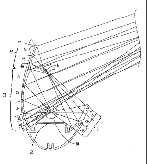
difference is that the present reflector has four reflector segments (1-4)
with sub-segments (la-
ic, 3a-3f, and 4a-4c) in sections 1, 3, and 4 as shown in Figure 1. It can be
seen that some of
these subsegments (1 a-1 c) focus light from the lamp 10 to focal points a, b,
c for example.
[0018] Additionally, section 2 is actually a reflective ballast cover located
over the lamp
10. As can be seen in prior art Figure 7, the prior art device only has simple
shaped "non-sub
segmented" parabolic and elliptical segments and no ballast cover reflector.
[0019] As shown in Figure 1, the reflector 1 has four reflector sections (1-4)
or reflector
segments and each of reflector segments 1, and 3-4, is broken into smaller sub-
sections or
"subsegments" (la-lc, 3a-3f, and 4a-4c). Each section is discussed in detail
below in reference
to Figures 2-5. Overall, the four reflector sections work in concert to direct
the resultant output
light only where desired as shown by the ray diagram in Figure 1.
Additionally, the reflector
achieves a superior asymmetric candlepower or candela distribution as shown in
the polar plot of
Figure 6 when compared to the prior art because it provides a smoother beam by
minimizing
striations (compare figures 9 and 10 to each other, and also compare Figs 11
and 12 to each
other, wherein the top of the present plots is smoother, i.e., reduced
striations or streaking in the
CA 02526865 2005-11-23
WO 2005/094337 PCT/US2005/010483
4
resultant light). Thus, for example, at a desired angle (110 degrees in the
example of Figure 6)
above the nadir (0 degrees) the maximum illuminance in candelas (see Figure
10) can be directed
to direct the beam uniformly in a desired direction to form a precise
asymmetric or triangular
shaped resultant illumination light profile (see Figure 13). As discussed
above, the present
resultant candela distribution curve is smooth (compare figures 9 and 10, and
also Figs 11 and 12
wherein the top of the present plots is smoother) which is excellent for
uniformly lighting
surfaces, such as ceilings for example without inducing streaking, striations,
or intensity lines. In
contrast, the prior art candela distribution curve shown in Figure 9 and 11 is
not as smooth and
has bumps (9)or striations forming a striated effect output curve. This
results in streaks of light
and uneven intensity on the surface.
[0020] Now the specific structure of a preferred embodiment will be discussed.
Referring to Figure 2, the first reflector is shown, elliptical reflector
section 1. The purpose of
this elliptically shaped reflector section 1 is to reflect light emitted from
the side of the bulb 9
that would otherwise go in an undesired direction. For example, as mentioned
above, viewers do
not desire to see the bulb 9 and the glare that can result from directly
viewing the bulb 9.
Additionally, for purposes of precise illumination of a target such as a sign,
the rays are directed
where desired. A comparison of prior art Figure 7 and to present Figure 13
shows that a similar
structure is not present in the prior art and that the resultant output beam
and candela distribution
is very different. Thus, elliptical reflector section 1 acts like a wall or
extended lip to minimize
the view of the bulb 9 from the users line of sight. The elliptical reflector
section 1 is preferably
made with a specular reflective surface as opposed to a diffuse surface
although a diffuse surface
could also be used. Additionally, as shown in Figure 2, there are three sub-
sections (la, lb, lc)
and each focuses the light from the lamp 10 as shown in Figure 2 to three
specific focal points
(a,b,c) as shown by the ray diagram. In this embodiment the sub-sections (la,
lb, 1c) are each
elliptically shaped sections. Other shapes are contemplated as well for the
segments and
subsegments.
[0021] Referring to Figure 3, the second reflector is shown, ballast cover
reflector 2. As
can be seen in Figure 7 which shows the design from prior art patent
3,679,893, no such ballast
CA 02526865 2005-11-23
WO 2005/094337 PCT/US2005/010483
cover reflector is included in the prior art patent. The purpose of the
present embodiment second
reflector section is to reflect light outward from underneath the lamp in a
diffuse mariner.
Therefore, the ballast reflector cover 2 is preferably made of a matte or
diffuse finish. This
section is not preferably made of multiple segments, but it is preferably one
flat section. The
section may also be curved so long as it is not specular. This surface is
preferably a highly
reflective matte surface, for example painted white. The reason this surface
is preferably matte
and not specular is that a specular surface would create a second image of the
light source, lamp
10, and create an undesirable resultant candlepower distribution.
[0022] Referring to FIG. 4, this third section termed first parabolic section
3, produces
the main light output from the system. It is broken into six sub-sections (3a,
3b, 3c, 3d, 3e, 30
which are aimed across at the target surface (e.g., wall, ceiling, etc.). As
the sub-section surfaces
are able to substantially "see" over the lamp, they are directed at lower and
lower angles to
produce high peak candlepower and fast runback.
[0023] Referring to FIG. 5, light reflected from the elliptical reflector
section 1 which
would otherwise be incident upon an observer's eyes is reflected and directed
to second
parabolic section 4 and is subsequently reflected out across the target
surface to reinforce the
asymmetric light pattern propagated from first parabolic section 3 as shown in
the ray diagram of
Figure 1 by sub sections (4a, 4b, and 4c).
[0024] The resulting candlepower illuminance distribution in candelas, shown
in FIG. 6,
is has an increase in peak candlepower and increase in energy efficiency over
a known three
segment reflector design of U.S. Patent 3,679,893. For example in tests it was
shown that peak
candlepower using a 54W T5/HO lamp is 2520 cd for the prior art whereas peak
candlepower
using a 54W T5/HO lamp is 2774 cd (about 10% higher) for this specific
embodiment of the
present invention. Additionally, streaking was mitigated and a more even
illumination was
resultant. Performance may vary and the different embodiments with different
shapes are also
contemplated so this data is for purposes of example only and should not be
considered to be
limiting.
CA 02526865 2005-11-23
WO 2005/094337 PCT/US2005/010483
6
[0025] This increase in performance is due part to the present structure
minimizing the
effects of the inverse square law which dictates that candle power decreases
at a much greater
rate as it propagates further from the lamp source.
[0026] To summarize, an embodiment may comprise a reflector for a luminaire
comprising: a first reflector segment located near an opening on the
luminaire; a second
reflector segment structured as a ballast reflector; a third reflector segment
located in the rear of
the luminaire; and a fourth reflector segment located and structured to
reflect light reflected from
the first reflector segment. The reflector may also comprise an embodiment
wherein the first
reflector segment, the third reflector segment, and the fourth reflector
segment comprise sub-
segments which precisely direct light into a desired candela distribution for
illuminating surfaces
evenly at desired angles. The reflector may also comprise an embodiment
wherein the first
reflector segment comprises three sub- segments which focus light to three
focal points. The
reflector may also comprise an embodiment wherein the fourth reflector segment
comprises 3
sub-segments with focal points coincident to the focal points of the first
reflector segment and
wherein the fourth reflector segment reflects light from the focal points in
substantially parallel
rays. An embodiment of the reflector may also comprise an embodiment wherein
the third
reflective segment comprises multiple sub-segments all sharing a common focal
point coincident
with a light source of the luminaire and wherein each sub-segment reflects and
redirects light
from the light source substantially back around the light source so that the
light is directed
substantially parallel to light reflected from the fourth reflective segment
to further reinforce the
peak candlepower. The reflector may also comprise an embodiment wherein the
second
reflective section has a matte finish and reflects the light energy from the
source in a lambertian
distribution so as not to create a second "false" image of the light source in
the other reflector
segments. The reflector may also comprise an embodiment wherein the three sub-
segments
which focus light to three focal points are each elliptical shaped. The
reflector may also
comprise a first elliptical shaped reflector segment located near an opening
on the luminaire; a
second flat and diffuse reflector segment structured as a ballast reflector; a
third parabolic shaped
reflector segment located in the rear of the luminaire; and a fourth parabolic
shaped reflector
segment located and structured to reflect light reflected from the first
reflector segment; wherein
CA 02526865 2005-11-23
WO 2005/094337 PCT/US2005/010483
7
the reflectors precisely direct light into a desired candela distribution for
illuminating surfaces
evenly at desired angles. The reflector may also comprise a luminaire comprise
a first reflector
means; a second reflector means structured as a ballast reflector; a third
reflector means; and a
fourth reflector means located and structured to reflect light reflected from
the first reflector
segment; wherein the reflectors precisely direct light into a desired candela
distribution for
illuminating surfaces evenly at desired angles.
[0027] Thus, it is seen that a four segment reflector and luminaire are
presented. One
skilled in the art will appreciate that the invention can be practiced by
other than the described
embodiments, which are presented for purposes of illustration and not of
limitations.