Note: Descriptions are shown in the official language in which they were submitted.
CA 02526871 2005-10-07
WO 2004/089679 PCT/GB2004/001594
STATION DESIGN FOR PERSONAL RAPID TRANSPORT SYSTEMS
This invention relates to the design of stations in a
personal rapid transport system.
In general, a personal rapid transport (PRT) system
comprises a dedicated guideway or track on which individual
vehicles travel between stations. Each vehicle contains
only one passenger or group of passengers, and the vehicle
travels continuously between the starting point and the
destination without stopping at any intermediate stations.
PRT systems thus provide a compromise between a
conventional mass transport system such as buses, trains
and metro systems, and individual passenger cars.
An example of a PRT system is disclosed in US 4061089. In
that system, a station is provided on a bypass guideway
branched off the main guideway. Lateral bays or "slots"
extend from the bypass guideway. Vehicles enter these
slots to drop off or pick up passengers. While in the
slots, the vehicles do not obstruct other traffic passing
along the bypass guideway. However, manoeuvring the
vehicles in to and out of the slots is not straightforward
and requires mechanical handling of the vehicles. While
this mechanical handling takes place, the vehicle may
obstruct other vehicles travelling along the bypass
guideway.
Another difficulty arising in stations is that steered
vehicles require a significant distance in which to move
close to a platform edge. Consequently, if a station is
designed like a conventional railway station, with a single
generally straight platform edge, it will not be possible
to park vehicles sufficiently close to the platform to
1
CA 02526871 2011-03-21
achieve a sufficiently narrow gap (for example, of less than 50 mm)
to avoid the danger of passengers injuring themselves as they move
into or out of the vehicle. This is particularly so if other
vehicles are already distributed along the platform.
According to the present invention there is provided a personal
rapid transit system comprising a dedicated guideway on which
individual steered passenger vehicles travel between stations, a
station of the system comprising a portion of the guideway bounded
on at least one side by a platform, the width of the guideway
portion being sufficient for travelling vehicles of the system to
travel along a transit path in the normal travel direction of the
vehicles unobstructed by vehicles parked on the guideway against the
platform, the platform extending generally parallel to the transit
path and comprising a plurality of bays for receiving parked
vehicles, each bay being defined by a respective parking section of
the platform edge, which parking section extends obliquely to the
transit path, whereby a steered vehicle of the system can move from
the transit path while maintaining a forwards travel direction of
the vehicle, to park against the parking section of the platform
edge of a respective one of the bays by turning from the transit
path through an acute angle, the parking sections of adjacent bays
being connected to each other by a transition section which extends
from the front end of one of the parking sections to the rear end of
the other.
The parking section is preferably straight, and may be inclined to
the transit path travel direction by an angle of less than 45
degrees. In a preferred embodiment, this angle is in the range of
10 to 20 degrees.
A vehicle entering the station is thus able to turn off the transit
path through a relatively small angle and then continue along a
substantially straight path to park very close to the parking
section, eliminating any substantial gap between the vehicle and the
platform.
2
CA 02526871 2005-10-07
WO 2004/089679 PCT/GB2004/001594
The bays may be distributed along the platform in a
direction parallel to the transit path. The parking
sections of adjacent bays may be joined to each other by a
transition section which extends from the front end of the
parking section of one bay to the rear end of the parking
section of the adjacent bay. In this context, "front" and
"rear" relate to the normal direction of travel of the
vehicles. Thus, in operation, a vehicle entering the bay
from the transit path will move parallel to the parking
section towards the transition section, and stop with one
side of the vehicle adjacent the platform at the parking
section.
The transition section may be concavely curved with a
radius of curvature greater than the turning circle of the
vehicle, so that the vehicle may leave the bay without
reversing so as to return to the transit path.
Alternatively, the vehicle may perform a relatively short
reversing manoeuvre before moving forwards to rejoin the
transit path.
The length of the parking. sections of the platform edge
region is preferably approximately equal to, or perhaps
slightly less than, the length of the vehicles of the PRT
system.
In a preferred embodiment, the guideway portion, including
the transit path, is straight, and the bays are distributed
along the platform in a line generally parallel to the
guideway portion. The parking sections of the bays are
parallel to each other and the perpendicular spacing
between them is not less than one vehicle width.
3
CA 02526871 2005-10-07
WO 2004/089679 PCT/GB2004/001594
It is desirable for several reasons for the main track of a
PRT system to be elevated above ground level. This
minimises obstruction to existing road traffic, but also
reduces severance by the main track. That is, elevation of
the main track does not provide a barrier to vehicles and
pedestrians wishing to cross from one side of the track to
the other.. Elevating the main track avoids the needs for
expensive bridges and underpasses.
It is not economically practical for vehicles to stop at
stations while on the main track. This would obstruct the
flow of other vehicles which may not need to stop at the
same station. Consequently, it is known to divert vehicles
off the main track on to a bypass track which passes
through the station. Vehicles then leave the main track to
pass along the bypass track for loading and unloading at
the station. Where the main track is. elevated, it is
conventional for the bypass tracks passing through stations
to be at the same level as the main track. This involves
considerable capital expense, since the entire station
structure needs also to be elevated. Furthermore, measures
such as elevators and escalators need to be provided to
transport passengers between ground level and the station.
According to a second aspect of the present invention,
there is provided a station in a personal rapid transport
system comprising a main track along which vehicles of the
system travel between a departure station and a destination
station, the station being provided on a bypass track which
is branched from the main track, the bypass track extending
through the station at a level below that of the stretch of
the main track which passes the station.
4
CA 02526871 2005-10-07
WO 2004/089679 PCT/GB2004/001594
In one embodiment in accordance with this aspect of the
present invention, the bypass track departs from, and
rejoins, the main track on the same side of the main track,
in which case the bypass track, as it extends through the
station, is generally parallel to the main track. In an
alternative embodiment, the bypass track leaves the main
track on one side of the main track. and rejoins on the
other side. In this embodiment, the station and the bypass
track extending through it, are situated beneath the main
track.
A platform may be provided on one or both sides of the
bypass track as it passes through the station.
According to a third aspect of the present invention, there
is provided a personal rapid transit system comprising a
main track along which vehicles of the system travel
between a departure station and a destination station, the
station being provided on bypass tracks which are branched
from the main track on opposite sides of the main track,
the bypass tracks extending through the station.
A bridge may be provided over the main track, to connect
platforms situated beside the bypass tracks. The platforms
may, for example, be situated on the sides of the bypass
tracks away from the main track.
For a better understanding of the present invention, and to
show how it may be carried into effect, reference will now
be made, by way of example, to the accompanying drawings,
in which:-
Figure 1 shows a guideway portion of a personal rapid
transport system;
5
CA 02526871 2005-10-07
WO 2004/089679 PCT/GB2004/001594
Figure 2 indicates diagrammatically the travel paths of
vehicles entering and leaving the guideway portion shown in
Figure 1;
Figure 3 shows an alternative vehicle travel path;
Figure 4 shows a schematic station configuration.
Figure 5 shows an alternative schematic station
configuration;
Figure 6 is a partial view taken generally in the direction
of the arrow VI in Figure 5; and
Figure 7 shows a third schematic station configuration.
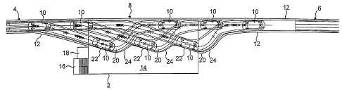
The guideway portion shown in Figure 1 passes through a
station represented by a rectangular boundary 2. The
guideway portion includes an entrance section 4 and an exit
section 6, which comprise parallel-sided track ways.
Between the sections 4 and 6 there is an intermediate
section 8 which passes through the station 2. Vehicles 10
are represented in Figure 1, with moving vehicles shown in
relatively faint outline, and stationary vehicles shown in
relatively heavy outline. The vehicles have steered front
wheels.
The sections 4 and 6 are single-track guideways bounded by
walls 12. On one side of the guideway, the wall 12
continues along the intermediate portion 8, but on the
other side the wall 12 terminates at the station 2. Within
the station 2 there is a platform 14 which is accessible by
passengers by means of stairs 16 and a lift 18.
6
CA 02526871 2005-10-07
WO 2004/089679 PCT/GB2004/001594
The edge of the platform bounding the intermediate guideway
8 has a scalloped form defining a plurality of bays 20
(three in the embodiment shown in Figure 1). It will be
appreciated that these bays are offset laterally from a
notional transit path through the intermediate section 8 in
alignment with the sections 4 and 6. Consequently,
vehicles 10 parked in the bays 20 will not obstruct
vehicles travelling along the transit path to or from one
or other of the bays 20.
Each bay 20 is defined by a straight parking section 22 and
a transition portion 24 of the edge of the platform 14.
The parking sections 22 are parallel to each other and are
inclined at an angle of approximately 15 to the direction
of the transit path. Each parking section 22 has a length
which is approximately equal to that of each vehicle 10,
although it will be appreciated that the parking section 22
of the bay 20 nearest to the entry section 4 is extended in
order to merge with that section. Thus, as shown in Figure
1, each bay 20 may be occupied by a single vehicle parked
side on to the parking section 22, so that side doors of
the vehicle open on to the platform 14. The transition
section 24 of each bay 20 extends from the front end of the
respective parking section 22 to the rear end of the
parking section of the next bay 20 to the front, with the
exception of the transition portion of the bay 20 nearest
to the exit section 6, which merges into that section.
The oblique orientation of the parking sections 22 means
that vehicles 10, steered by their front wheels, can move
off the transit path into a bay by a simple turn through
15 , ie the angle of inclination of the parking sections 22
relative to the transit path. The vehicle can then proceed
7
CA 02526871 2005-10-07
WO 2004/089679 PCT/GB2004/001594
into the bay, stopping with its side not more than 50 mm
from the platform edge.
As shown in Figure 1, the transition sections 24 are
concave, and curved with a radius somewhat larger than the
radius of the minimum turning circle of the vehicles 10.
As a.result, a vehicle 10 parked in a bay 20 can leave the
bay by moving forwards past the transition section 24 to
rejoin the transit path: This manoeuvre is represented for
the vehicle 10A in Figure 2, the travel path of which is
shown for a manoeuvre from the transit path at position
10A' to a bay 20 in position 10A'' and then returning to
the transit path at position 10A '' '.
An alternative manoeuvre is shown in Figure 3, which
appropriate if the bays 20 need to be more closely stacked
to increase the capacity of the station 2 without extending
its length. In the manoeuvre shown in Figure 3, the
vehicle 10A is reversed slightly from the parked position
before moving forwards to rejoin the transit path, while
avoiding a vehicle 10B parked in the adjacent bay 20.
It should be noted that, in Figures 2 and 3, the guideway
portion is shown only diagrammatically, without boundary
walls such as shown at 12 in Figure 1.
Figures 4 to 6 show different embodiments of a station
which may or may not include the platform arrangement shown
in Figures 1 to 3.
With reference to Figure 4, the PRT system comprises a main
through track 30 which is elevated above ground level and
runs past a station 32. At the station 32, there is a
platform 34 disposed beneath the main track 30. Two branch
8
CA 02526871 2005-10-07
WO 2004/089679 PCT/GB2004/001594
bypass tracks 36 are branched from the main track 30 and
extend past the platform 34 in a direction which is
parallel to that of the track 30, with one on each side.
In use, passengers may reach the platform 34 from the ends,
after passing underneath portions 38 of the bypass tracks
shortly after they leave, or rejoin, the elevated main
track 30. At these regions, the bypass track 36 is sloping
downwards from the main track 30 towards the level of the
platform 34, and consequently there is sufficient headroom
for the passage of passengers. The portions 38 on the left
of the station as seen in Figure 4 are used for
deceleration of the vehicles 10 after they have left the
main track 30. The portions of the bypass track 38 to the
right as seen in Figure 4 are used for acceleration of the
vehicles 10 before they rejoin the track 30. Consequently,
vehicles travelling along the track 30 past the station may
travel at the full normal speed, so minimising congestion
on the main track 30.
There may be a lift 40 to provide access to the platform 34
to disabled people, or, in some circumstances, where the
platform 34 is situated some level above ground level, but
nevertheless beneath the main track 30.
The platform 34, and the bypass tracks 36, may be
constructed in the manner disclosed in Figures 1 to 3.
Alternatively, however, each bypass track may comprise a
loading bay 42 and one or more waiting bays 44. In use,
passengers embark and disembark from vehicles in the
loading bay 42. Any empty vehicles waiting for new
passengers will stand in the waiting bay 44. Vehicles
entering the station with passengers intending to disembark
will be diverted to the bypass track having the shortest
9
CA 02526871 2005-10-07
WO 2004/089679 PCT/GB2004/001594
wait before reaching the loading bay 42, or alternatively
may be permitted to disembark in a waiting bay 44.
The station configuration shown in Figures 5 and 6 also
comprises a main track 30 and bypass tracks 36, having
acceleration and deceleration portions 38. In the station
configuration shown in Figures 5 and 6, the main track
extends approximately at ground level (shown in Figure 6 in
a shallow cutting 46). The bypass track 36 is also
substantially at ground level. The platforms 34 of the
station shown in Figure 5 are disposed on the side of the
bypass tracks 36 away from the main track 30.
Consequently, passengers arriving at the station to
transfer to a vehicle 30 can approach from either side
without needing to cross either the main track 30 or the
bypass tracks 36. However, a bridge 48 may be provided
extending between the platforms 34 and passing over the
main track 30 at a position before (or after) that at which
the bypass tracks 36 branch off (or rejoin) the main track
30.
Figure 7 shows a station configuration which is a
modification of that shown in Figure 4 and, again, similar
reference numbers are used to designate similar features.
In the configuration of Figure 7, the bypass track 36
leaves the main track 30 on one side, then passes beneath
the main track 30 to rejoin on the other side. Thus, the
station itself is situated directly beneath the main track
30 and, again, passengers may move from one side to the
other of both the main track 30 and the bypass track 36 by
passing beneath the deceleration and acceleration portions
38.