Note: Descriptions are shown in the official language in which they were submitted.
CA 02526934 2005-11-23
WO 2005/001968 PCT/CA2004/000933
-1-
APPARATUS AND METHOD FOR CONDUCTING FLUID IN A FUEL CELL
AND FUEL CELL EMPLOYING SAME
BACKGROUND OF THE INVENTION
1. Field of Invention
The present invention relates to electrochemical fuel cells and more
particularly to a reactant supply apparatus for a fuel cell, a fuel cell and
fuel
cell stack employing the same.
2. Description of Related Art
Electrochemical fuel cells convert fuel and an oxidant to electricity and a
reaction product. A typical fuel cell includes a cathode, an anode, and a
membrane. The membrane is sandwiched between the cathode and anode.
Fuel, in the form of hydrogen, is supplied to the anode where a catalyst,
usually platinum, catalyzes the following anode reaction:
Anode reaction: H2 -p 2H+ + 2e
Hydrogen separates into hydrogen ions and electrons. The hydrogen (cations)
migrate through the membrane to the cathode. The electrons migrate via an
external circuit in the form of electricity.
An oxidant, such as pure oxygen or air containing oxygen, is supplied to the
cathode where it reacts with the hydrogen ions that have crossed the
membrane and with the electrons from the external circuit to form liquid water
as the reaction product. The cathode reaction is also usually catalyzed by
platinum and occurs as follows:
Cathode reaction: Y202 + 2H+ + 2e - H2O
CA 02526934 2005-11-23
WO 2005/001968 PCT/CA2004/000933
-2-
Thus the fuel cell generates electricity and water through the electrochemical
reaction. Water is formed at the cathode.
Typically, the electrochemical reaction also supports a phenomenon called
water pumping. As each cation (proton) migrates through the membrane, it
transports or drags along several water molecules with it. Thus, there is a
net
transport of water to the cathode. Water pumping adds water to the product
water formed at the cathode as a result of the electrochemical reaction in the
fuel cell.
Solid polymer fuel cells generally comprise a Membrane-Electrode Assembly
(MEA). The MEA consists of a solid polymer electrolyte or ion exchange
membrane situated between and in contact with two electrodes, made of
porous, electrically conducting sheet material, which act as the anode and
cathode. The electrodes are typically made from carbon fiber paper or cloth.
At the interface of the electrode and membrane is a layer of catalyst to
facilitate the electrochemical reaction. The MEA is placed between two
electrically conductive plates, commonly formed from graphite. These plates
have one or more reactant flow passages impressed on their surfaces. The
reactant flow passages direct the flow of a reactant to the electrode and
carry
away water produced at the cathode due to the fuel cell reaction and due to
water pumping.
Conventional reactant flow passages are generally long, narrow and
serpentine in shape. Typically, due to capillary action, water adheres to
walls
of the reactant flow passages, requiring considerable pressure to remove it.
Failure to remove this water can result in the accumulation of water at the
cathode, and this can create problems for the operation of the fuel cell. The
presence of water in the vicinity of the catalyst layer reduces the
accessibility
of the catalyst to the reactant, a phenomenon commonly referred to as
"flooding." Also, the presence of water, often in the form of droplets, can
CA 02526934 2010-03-01
-3-
substantially block the flow of oxidant reactant through the reactant flow
passages. "Dead spots" can form in areas where channel passages are
blocked. In addition, the failure to remove water from the cathode can result
in
localized hot spots in the membrane as the removal of water is important to
cooling the fuel cell. Localized hot spots can result in pinhole failure of
the
membrane, for example. These conditions can result in a reduction of
available power from the fuel cell, or failure in operation of the fuel cell.
SUMMARY OF THE INVENTION
In accordance with one aspect of the invention, there is provided an
apparatus for conducting fluid in a fuel cell. The apparatus includes a
unitary
gas-impermeable body having, a face having a recessed surface and a wall
extending around the recessed surface, the recessed surface and the wall
defining a fluid dispersion area. The apparatus also includes a plurality of
spaced apart protrusions protruding from the recessed surface in the fluid
dispersion area such that portions of the recessed surface extend all around
each of the protrusions. Each protrusion has a protrusion surface spaced
apart from the recessed surface. The plurality of spaced apart protrusions are
arranged in rows and columns, and alternate columns of protrusions are
staggered relative to adjacent columns. The apparatus also includes an inlet
opening, a first plurality of inlet conduits, and a distribution area between
the
inlet opening and the first plurality of conduits for distributing fluid to
the first
plurality of conduits for communication to the fluid dispersion area. The
apparatus further includes an outlet opening, a plurality of outlet conduits,
and
a receiving area between said outlet opening and said plurality of outlet
conduits to facilitate communication of fluid between the fluid dispersion
area
and the outlet opening.
The recessed surface may be generally planar.
The recessed surface may have a generally rectangular shape.
The recessed surface may have a generally trapezium shape.
CA 02526934 2010-03-01
-4-
The recessed surface may have a length and a width, the width decreasing
from a first width adjacent the inlet opening to a second width adjacent the
outlet opening.
The body may include a plate.
The recessed surface may have a length and a width, the width decreasing
from a first width adjacent the inlet opening to a second width adjacent the
outlet opening.
The body may be formed from a castable electrically-conductive corrosion-
resistant material.
The body may be formed from graphite material.
The body may be formed from a metal, the metal being coated with at least
one of graphite powder, titanium, and gold.
The body may be formed from a composite material.
The composite material may be coated with at least one of graphite powder,
titanium, and gold.
The protrusion surface may have a generally curved shape.
The protrusion surface may have at least one of a rectangular, circular and
triangular shape.
The protrusion surface may lay in a common plane.
The recessed surface may have a total recessed surface area and each
protrusion surface may have a respective surface area and a sum of the
respective surface areas may be approximately equal to the total recessed
surface area.
The protrusion may be spaced apart from adjacent protrusions by a common
distance.
The protrusion surface may be disposed approximately 0.5 mm to 0.8 mm
from the recessed surface.
CA 02526934 2010-03-01
-5-
The body may have a groove extending around the recessed surface, for
receiving a seal for sealing the face to an adjacent component in the fuel
cell.
The apparatus may further include a first bridge member and the face may
have a first support surface adjacent the inlet conduit for supporting the
first
bridge member over the inlet conduit.
The apparatus may further include a second bridge member and the face may
have a second support surface adjacent the outlet conduit for supporting the
second bridge member over the outlet conduit.
The groove may further include groove portions adjacent the first support
surface. The seal may include an inner portion operable to lie in the groove
portions and the first bridge member may be operable to support the inner
portion.
The body may include a plate, the face being on the plate and being generally
flat.
The plate may include cooling means for cooling the plate, on a side of the
plate opposite the face.
The cooling means may include parallel spaced apart grooves formed in the
plate.
The protrusions may be formed in an array, the array defining an active area
of the plate and the cooling means may be disposed opposite the active area.
The body may have an inwardly facing side and an outwardly facing side, the
recessed surface being formed in the inwardly facing side, the inwardly facing
side being operable to contact a gas diffusion layer of a membrane of the fuel
cell and the grooves being formed in the outwardly facing side to facilitate
cooling.
The body may have an inwardly facing side and an outwardly facing side, the
recessed surface being formed in the inwardly facing side, the inwardly facing
side being operable to contact a gas diffusion layer of a membrane assembly
of the fuel cell and the cooling means may be formed in the outwardly facing
CA 02526934 2010-03-01
-6-
side and may include a second recessed surface and a second wall extending
around the second recessed surface, the second recessed surface and the
second wall defining a second fluid dispersion area. The cooling means may
also include a second plurality of spaced apart protrusions protruding from
the
second recessed surface in the second fluid dispersion area such that
portions of the second recessed surface extend all around each of the
protrusions, each protrusion having a protrusion surface spaced apart from
the second recessed surface, and a second inlet opening operable to receive
cooling fluid, a second inlet conduit, a second outlet opening and a second
outlet conduit, the second inlet conduit being in communication with the
second inlet opening and the second fluid dispersion area to facilitate
communication of cooling fluid from the second inlet opening to the second
fluid dispersion area and the second outlet conduit being in communication
with the second fluid dispersion area and the second outlet opening to
facilitate communication of the cooling fluid between the second fluid
dispersion area and the second outlet opening.
The apparatus may further include openings extending through the plate,
adjacent the recessed surface, for receiving mounting devices therethrough,
for mounting the plate in the fuel cell.
The apparatus may further include an electrical conduit mount for mounting a
first electrical conduit to the body such that the first electrical conduit
extends
generally perpendicular to the face of the body.
The apparatus may further include a first electrical conduit connected to the
electrical conduit mount, the first electrical conduit having a first circuit
termination portion.
The apparatus may further include an insulator on the first electrical
conduit.
The apparatus may further include mounting openings in the body for
mounting the body to the fuel cell.
The apparatus may further include a conduit opening in the body for receiving
a conduit operable to conduct electrical power from the fuel cell.
CA 02526934 2010-03-01
-7-
In accordance with another aspect of the invention, there is provided a fuel
cell stack apparatus. The fuel cell stack apparatus includes a first fuel cell
membrane assembly having a proton exchange membrane and anode and
cathode gas diffusion layers on opposite sides of the proton exchange
membrane. The fuel cell stack apparatus also includes a first fluid supply
apparatus comprising a gas impermeable body having a first inwardly facing
side and a first outwardly facing side, the first inwardly facing side being
in
contact with the anode gas diffusion layer. The first inwardly facing side has
a
first recessed surface and a first wall extending around the first recessed
surface, the first recessed surface and the first wall defining a first fluid
dispersion area. The first inwardly facing side also includes a first
plurality of
spaced apart protrusions protruding from the recessed surface in the first
fluid
dispersion area such that portions of the recessed surface extend all around
each of the protrusions, each protrusion having a protrusion surface spaced
apart from the recessed surface. The protrusion surfaces are operable to
contact the anode gas diffusion layer. The plurality of spaced apart
protrusions are arranged in rows and columns, and alternate columns of
protrusions are staggered relative to adjacent columns. The first inwardly
facing side further includes a first inlet opening for receiving anode
reactant
fluid. The first inwardly facing side further includes a first plurality of
inlet
conduits, and a first distribution area between the first inlet opening and
the
first plurality of inlet conduits for distributing anode reactant fluid to the
first
plurality of inlet conduits for communication of the anode reactant fluid to
the
first fluid dispersion area. The first inwardly facing side further includes a
first
outlet opening and a first outlet conduit, the first outlet conduit being in
communication with the first fluid dispersion area and the first outlet
opening
to facilitate communication of anode reactant fluid between the first fluid
dispersion area and the first outlet opening. The fuel cell stack apparatus
also
includes a second fluid supply apparatus comprising a - unitary gas-
impermeable body having a second inwardly facing side and a second
outwardly facing side, the second inwardly facing side being in contact with
the cathode gas diffusion layer and having a second recessed surface and a
second wall extending around the second recessed surface, the second
CA 02526934 2010-03-01
-8-
recessed surface and the second wall defining a second fluid dispersion area.
The second outwardly facing side of the second fluid supply apparatus
includes cooling provisions for cooling the second fluid supply apparatus. The
unitary gas-impermeable body further includes a second plurality of spaced
apart protrusions protruding from the second recessed surface such that
portions of the second recessed surface extend all around each of the
protrusions, each protrusion having a protrusion surface spaced apart from
the second recessed surface, wherein the plurality of spaced apart
protrusions are arranged in rows and columns. Alternate columns of
protrusions are staggered relative to adjacent columns. The unitary gas-
impermeable body also includes a second inlet opening operable to receive
cathode reactant fluid. The body also includes a second plurality of inlet
conduits, and a second distribution area between the second inlet opening
and the second plurality of inlet conduits for distributing cathode reactant
fluid
to the second plurality of inlet conduits for communication of the cathode
reactant fluid to the second fluid dispersion area. The unitary gas-
impermeable body also includes a second outlet opening and second outlet
conduit, the second outlet conduit being in communication with the second
fluid dispersion area and the second outlet opening to facilitate
communication of excess cathode reactant fluid and water from the cathode
gas diffusion layer from the second fluid dispersion area to the second outlet
opening.
The cooling means may include a third face on the second fluid supply
apparatus, the third face having a third recessed surface and a third wall
extending around the third recessed surface, the third recessed surface and
CA 02526934 2009-06-22
-9-
the third wall defining a third fluid dispersion area. The cooling means may
also include a third plurality of spaced apart protrusions protruding from the
third recessed surface in the third fluid dispersion area such that portions
of
the third recessed surface extend all around each of the protrusions, each
protrusion having a protrusion surface spaced apart from the recessed
surface. The cooling means may also include a third inlet opening for
receiving cooling fluid, a third inlet conduit, a third outlet opening for
draining
cooling fluid and a third outlet conduit. The third inlet conduit is in
communication with the third inlet opening and the fluid dispersion area to
facilitate communication of cooling fluid from the third inlet opening to the
third
fluid dispersion area and the third outlet conduit is in communication with
the
third fluid dispersion area and the third outlet opening to facilitate
communication of cooling fluid between the third fluid dispersion area and the
third outlet opening.
The cooling means may include a plurality of parallel grooves in the outwardly
facing side of the second fluid supply apparatus the groves being operable to
conduct cooling fluid to facilitate cooling of the second fluid supply
apparatus.
The fuel cell stack apparatus may further include first and second current
collector plates in contact with the first and second fluid supply apparatuses
respectively, each of the first and second current collector plates having an
inwardly facing side and an outwardly facing side. The apparatus may also
further include first and second electrical conduits respectively secured to
at
least one of the inwardly and outwardly facing sides of the first and second
current collector plates respectively. The apparatus further includes first
and
second insulators on the first and second conduits respectively, and the first
and second conduits may be secured to the first and second current collector
plates such that the first and second conduits extend through openings in
components of the fuel cell and are insulated from the components by the first
and second insulators, such that the first and second conduits extend from a
same end of the fuel cell.
CA 02526934 2009-06-22
-10-
Other aspects and features of the present invention will become apparent to
those ordinarily skilled in the art upon review of the following description
of
specific embodiments of the invention in conjunction with the accompanying
figures.
BRIEF DESCRIPTION OF THE DRAWINGS
In drawings which illustrate embodiments of the invention,
Figure 1 is an exploded side view of a fuel cell apparatus according to a
first embodiment of the invention;
Figure 2 is an end view of the fuel cell apparatus shown in Figure 1;
Figure 3 is a plan view of an inwardly facing side of an anode end plate of
the fuel cell apparatus shown in Figure 1;
Figure 4 is a plan view of an outwardly facing side of an anode current
collector plate shown in Figure 1;
Figure 5 is a plan view of an inwardly facing side of the anode current
collector plate;
Figure 6 is a plan view of an outwardly facing side of the first fluid supply
apparatus of the fuel cell shown in Figure 1;
Figure 7 is a plan view of an inwardly facing side of the first fluid supply
apparatus of Figure 6;
Figure 8 is a plan view of an inwardly facing side of a second fluid supply
apparatus of the fuel cell shown in Figure 1;
Figure 9 is a plan view of an outwardly facing side the second fluid supply
apparatus shown in Figure 8;
CA 02526934 2009-06-22
-11-
Figure 10 is a plan view of a cathode current collector plate of the fuel cell
apparatus shown in Figure 1;
Figure 11 is a top view of the fuel cell shown in Figure 1 showing cooling
provisions formed in the first and second fluid supply apparatus;
Figure 12 is a top view of a fuel cell stack according to the second
embodiment of the invention showing mating grooves that form
conduits to provide for cooling of fluid supply apparatus of
individual fuel cells within the stack;
Figure 13 is an exploded view of a fuel cell apparatus according to an
alternative embodiment of the invention in which circuit
terminations of the fuel cell are disposed on a same end thereof.
Figure 14 is an exploded view of a fuel cell apparatus or optional fuel cell
stack, according to a third embodiment of the invention;
Figure 15 is a plan view of an end plate of the fuel cell apparatus shown in
Figure 14;
Figure 16 is a plan view of an inwardly facing side of the end plate shown
in Figure 15;
Figure 17 is a plan view of an outwardly facing side of a first humidifier
plate of a humidifier of the fuel cell apparatus shown in Figure
14;
Figure 18 is a plan view of an inwardly facing side of the first humidifier
plate shown in Figure 17;
Figure 19 is a plan view of an outwardly facing side of a second humidifier
plate of the fuel cell apparatus shown in Figure 14;
CA 02526934 2009-06-22
-12-
Figure 20 is a plan view of an inwardly facing side of the second humidifier
plate of Figure 19;
Figure 21 is a plan view of an outwardly facing side of a third humidifier
plate of the humidifier of the fuel cell apparatus shown in Figure
1;
Figure 22 is a plan view of an inwardly facing side of the third humidifier
plate of Figure 21;
Figure 23 is a plan view of an outwardly facing side of a first current
collector plate of the fuel cell apparatus shown in Figure 14;
Figure 24 is a plan view of an inwardly facing side of the current collector
plate shown in Figure 23;
Figure 25 is a plan view of an outwardly facing side of a first cooling plate
of the fuel cell apparatus shown in Figure 14;
Figure 26 is a plan view of an inwardly facing side of the first cooling plate
shown in Figure 25;
Figure 27 is a plan view of an outwardly facing side of an anode fluid
supply apparatus of the fuel cell shown in Figure 14;
Figure 28 is a plan view of an inwardly facing side of the anode fluid
supply apparatus shown in Figure 27;
Figure 29 is a plan view of an inwardly facing side of a cathode fluid supply
apparatus of the fuel cell shown in Figure 14; and
CA 02526934 2009-06-22
-13-
Figure 30 is a plan view of an outwardly facing side of the cathode fluid
supply apparatus shown in Figure 29;
Figure 31 is a plan view of an inwardly facing side of a second cooling
plate of the humidifier apparatus shown in Figure 14;
Figure 32 is a plan view of an outwardly facing side of the humidifier plate
shown in Figure 31;
Figure 33 is a plan view of an inwardly facing side of a second current
collector plate of the fuel cell apparatus shown in Figure 14;
Figure 34 is a plan view of an outwardly facing side of the current collector
plate shown in Figure 33;
Figure 35 is a plan view of an inwardly facing side of an end plate of the
fuel cell apparatus shown in Figure 14; and
Figure 36 is a plan view of a second end view of the fuel cell apparatus
shown in Figure 14;
Figure 37 is a top view of the humidifier and fuel cell shown in Figure 14
illustrating water humidification and cooling passages;
Figure 38 is an exploded view of a fuel cell apparatus according to a fourth
embodiment of the invention in which circuit termination conduits
protrude from a first end of the fuel cell apparatus; and
Figure 39 is a perspective view of an alternate configuration of an inwardly
facing side of the cathode reactant supply apparatus replacing
the one shown in Figure 29.
CA 02526934 2009-06-22
-14-
DETAILED DESCRIPTION
Referring to Figure 1, a fuel cell apparatus according to a first embodiment
of
the invention is shown generally at 10 in an exploded side view. The
apparatus includes a Membrane-Electrode Assembly (MEA) shown generally
at 12 comprising a proton-exchange membrane 14 and anode and cathode
carbon-cloth gas diffusion layers 16 and 18, respectively, forming anode and
cathode sides of the MEA, respectively. The fuel cell apparatus 10 further
includes first and second fluid supply apparatus 20 and 22 operable to contact
the anode and cathode gas diffusion layers 16 and 18, respectively, and to
deliver anode reactant (hydrogen gas) and cathode reactant (oxygen gas) to
the anode and cathode gas diffusion layers 16 and 18, respectively.
The first and second fluid supply apparatus 20 and 22 have inwardly and
outwardly facing sides 24 and 26, respectively. The inwardly facing sides 24
contact the anode and cathode gas diffusion layers 16 and 18, respectively,
and the outwardly facing sides 26 face outwardly away from the MEA and
contact anode and cathode current collector plates 28 and 30, respectively, in
the embodiment shown. Anode and cathode end plates 32 and 34 contact the
anode and cathode current collector plates 28 and 30, respectively.
The cathode end plate 34 includes a rubber gasket 36 disposed between the
cathode current collector plate 30 and the cathode end plate 34.
The anode end plate 32 has a plurality of openings to which are secured fluid
connectors, only two of which are shown at 38 and 40, for connecting to
hydrogen reactant supply and oxygen reactant exhaust conduits, respectively
(not shown). Clamping members, only two of which are shown at 42 and 44,
extend across and beyond the outer perimeter of the anode and cathode end
plates 32 and 34, respectively, and are pulled together by bolts, only two of
which are shown at 43 and 48, respectively, to securely hold all the
components together in tight mechanical proximity.
CA 02526934 2009-06-22
-15-
Referring to Figure 2, an end view of the fuel cell apparatus of Figure 1 is
shown generally at 50. In this view it can be seen that the anode end plate 32
has four openings, to which are connected the hydrogen supply connector 38,
oxygen exhaust connector 40 and to which are further connected a hydrogen
exhaust connector 52 and an oxygen supply connector 54.
Referring to Figure 3, an inwardly facing side 46 of the anode end plate 32 is
shown. The inwardly facing side 46 is flat with the exception of hydrogen and
oxygen supply openings 56 and 58 and hydrogen and oxygen exhaust
openings 60 and 62 in communication with the hydrogen and oxygen supply
connectors 38 and 54 and the hydrogen and oxygen exhaust connectors 52
and 40, respectively. The inwardly facing side 46 abuts an outwardly facing
side 47 of the anode current collector plate 28 shown in Figure 4.
Referring to Figure 4, the anode current collector plate 28 has a flat planar
surface and has four rectangular openings including an oxygen supply
opening 64, a hydrogen supply openings 66, a hydrogen exhaust opening 68
and an oxygen exhaust opening 70.
Referring to Figures 3 and 4, openings 56 and 66, 58 and 64, 60 and 68, and
62 and 70 are in communication with each other when sides 46 and 47 are in
contact with each other.
Referring to Figure 5, an inwardly facing side 72 of the anode current
collector
plate 28 is shown. This inwardly facing side 72 has a generally flat planar
surface with four rectangular openings 64, 66, 68 and 70 extending
therethrough. This inwardly facing side 72 abuts an outwardly facing side 74
of the first supply apparatus 20 shown in Figure 6.
Referring to Figure 6, in this embodiment, the first fluid supply apparatus 20
comprises a unitary gas impermeable body in the shape of a plate about 3
mm thick. The body may be formed from a castable, electrically conductive
corrosion resistant material such as graphite, for example. Alternatively, the
CA 02526934 2009-06-22
-16-
body may be formed from a metal and be coated with graphite powder,
titanium or gold, for example. The first fluid supply apparatus 20 includes
four
openings disposed in the four corners thereof, including hydrogen and oxygen
supply openings 76 and 78, and hydrogen and oxygen exhaust openings 80
and 82, respectively, which are in communication with openings 66, 64, 68
and 70, respectively. A groove 84 is formed in a perimeter of the outwardly
facing side 74 and is operable to receive a gasket 86 therein. The gasket 86
has adjacent portions, only two of which are shown at 88 and 90, around each
opening 76, 78, 80 and 82, such that portions of the gasket extending about
the perimeter of the face and the adjacent portions 88 and 90 completely
surround each opening 76, 78, 80 and 82 to seal the outwardly facing side 74
against the mating inwardly facing side 72 of the anode current collector
plate
28 shown in Figure 5 to prevent escape of gas between the inwardly facing
side 72 of the anode current collector plate 28 and the outwardly facing side
74 of the first fluid supply apparatus 20.
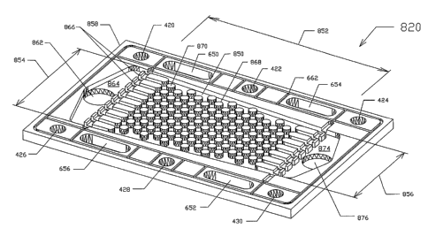
Referring to Figure 7, the inwardly facing side 24 of the first fluid supply
apparatus 20 may also be referred to as a first face side, and has a planar
surface 100 and a wall 102, defining a first generally rectangular shaped
recessed surface 104. A first plurality 106 of spaced apart contacts 108
protrude from the first recessed surface 104 such that portions of the first
recessed surface extend all around each of the contacts 108. Each contact
108 has a contact surface 110 spaced apart from the first recessed surface
104 by about 0.5 to 0.8 mm and each contact surface lies generally in the
same plane as the planar surface 100. The contacts 108 are arranged in rows
and columns with adjacent columns being staggered so that fluid travelling
between two adjacent contacts in a column is dispersed by a contact aligned
between the two adjacent contacts, in an adjacent column. Each contact is
spaced apart from an adjacent contact by the same, common distance which
may be about twice the diameter of a contact surface, for example, where the
contact surfaces 110 are circular. In this embodiment, each contact surface
110 has a circular shape with a diameter of about 4.76 mm. The contact
surfaces 110 may, however, be generally curved shaped, rectangular (e.g.,
CA 02526934 2009-06-22
-17-
waffle shaped), or triangular, for example. Generally, it is desirable if the
total
contact surface area is approximately equal to the total area between the
contacts, that is, the total recessed area.
The hydrogen supply opening 76 acts as an inlet opening in the body. First
and second inlet conduits 112 and 114 are formed in the first inwardly facing
side 24 and establish fluid communication between the hydrogen supply
opening 76 and the first recessed surface 104 to facilitate communication of
reactant from the hydrogen supply opening to the first recessed surface. The
first fluid supply apparatus 20 also has first and second outlet conduits 116
and 118 which establish communication between the first recessed surface
104 and the hydrogen exhaust opening 80 to facilitate communication of fluid
between the first recessed surface and the hydrogen exhaust opening. The
first inwardly facing side 24 is placed in contact with the anode gas
diffusion
layer 16 shown in Figure 1, such that a first reactant dispersion area is
formed
between the first recessed surface 104 and the anode gas diffusion layer
whereby reactant received at the hydrogen supply opening 76 is
communicated to the first reactant dispersion area and is supplied to the
anode gas diffusion layer, between the contacts 108.
The inwardly facing side 24 also has a groove 120 extending around the
recessed surface 104 for receiving a polymeric seal (not shown) for sealing
the face to the anode gas diffusion layer 16. The groove may be about 4.76
mm in depth and in width, for example. Support surfaces 122, 124 and 126
are formed in the first inwardly facing side 24 adjacent the first and second
inlet conduits 112 and 114 and are operable to support a first bridge member
128 transversely over the first and second inlet conduits 112 and 114 to
support an inner portion of the seal over the first and second inlet conduits
between the groove portions. A similar arrangement is provided adjacent the
first and second outlet conduits 116 and 118 to support the corresponding
portion of the seal thereover.
CA 02526934 2009-06-22
-18-
Referring back to Figure 1, in this embodiment, the proton-exchange
membrane 14 is formed of a polymer sheet having a thickness of between
about 0.050 mm to 0.1778 mm. The anode and cathode gas diffusion layers
16 and 18 are disposed on opposite sides of the proton exchange membrane
14 and provide gas for diffusion layers between the inwardly facing surfaces
of the fluid supply apparatus 20 and 22 and the membrane 14. The anode and
cathode gas diffusion layers are composed of a cloth woven of carbon fibers,
with a slurry of lampblack and a small portion of polytetrafluoroethylene
(PTFE or Teflon®) impressed and sintered into the interstices of the
fabric. The proton exchange membrane 14 thereby resides between
cushioning "blankets" of carbon cloth infused with carbon and PTFE particles,
in turn clamped between the first and second fluid supply apparatus 20 and
22, respectively. A catalyst, usually platinum, is applied as a slurry or
paste of
platinum-black and lampblack in a dilute solution of the polymer of which the
membrane is comprised. The catalyst may be included in the slurry applied to
the surface of the gas-diffusion cloth and the membrane. The two cloth layers
may then be placed next to the membrane, one on each side, and this three-
layer sandwich is hot-pressed together. The polymer component of the slurry
bonds to the membrane, uniting the three layers to form an integral structure
called the membrane-electrode assembly (MEA).
Alternatively, an ink comprised of minute particles of platinum supported on
lampblack particles may be suspended in a solution of the polymer material.
The ink-slurry is applied to both surfaces of the membrane, which is then hot-
pressed to bond the ink onto the membrane. The polymer material of the ink
intimately bonds to the polymer material of the membrane. The ink-coated
membrane is referred to as the MEA in this approach. A layer of un-catalyzed
gas diffusion cloth is then placed adjacent to each side of the membrane
when the cell is assembled.
Referring to Figure 8, the inwardly facing side 24 of the second fluid supply
apparatus 22 is shown generally at 130. This side is the same as the inwardly
facing side 24 shown in Figure 7. The apparatus includes oxygen supply and
CA 02526934 2009-06-22
-19-
oxygen exhaust openings 132 and 134, respectively, and hydrogen supply
and exhaust openings 136 and 138, respectively. The apparatus further
includes a groove arrangement 140, a recessed area 142 and contacts 144.
Pure oxygen may be received at the oxygen supply opening 132 and
conducted by inlet conduits 131 and 133 into the reactant dispersion area
formed between the recessed surface 142 and the cathode gas diffusion layer
(18) for use in the fuel cell reaction. Excess oxygen not consumed by the fuel
cell reaction may be conducted from the recessed surface 142 by outlet
conduits 135 and 137 to the oxygen exhaust opening 134 to be evacuated
through the oxygen exhaust opening.
Referring to Figures 1, 7 and 8, the first and second fluid supply apparatus
20
and 22, respectively, co-operate with the anode and cathode gas diffusion
layers 16 and 18, respectively, such that each gas diffusion layer (16,18)
allows reactant gas to diffuse from the dispersion area defined between it and
the recessed surface 104, 142 of its respective fluid supply apparatus
(20,22),
enabling areas (active areas) of the membrane 14 aligned with areas between
the contacts 108 and 144 of the respective fluid supply apparatus to become
active and generate current. Each gas diffusion layer 16,18 also forms an
electrically conducting path for current generated in the active areas to flow
laterally to areas where the contacts 108 and 144 of the respective fluid
supply apparatus 20,22 can conduct it perpendicularly through the fuel cell or
fuel cell stack. Each gas diffusion layer 16,18 also resiliently conforms to
surface irregularities on the membrane 14, improves the electrical contact
with
the membrane and provides some structural support for the membrane.
In addition, water produced by the electrochemical reaction of the fuel cell
at
the cathode gas diffusion layer 18, and any water dragged through the
membrane by the hydrogen ions employed in the reaction, is received in the
dispersion area, in areas between the contacts 144. The water may fall under
gravity, for example between adjacent columns or rows of contacts toward the
oxygen exhaust opening 134 or may simply be directed toward the oxygen
exhaust opening 134 by the flow of oxygen in the dispersion area. Desirably,
CA 02526934 2009-06-22
-20-
the contacts 144 are spaced apart such that the surface tension of a water
droplet is insufficient to maintain the water droplet between adjacent
contacts,
causing it to fall between the contacts, when subjected to the force of
gravity,
when subjected to the oxygen under pressure in the dispersion area and/or
when subjected to other forces. The water is free to travel relatively
unimpeded between adjacent contacts 144 and has a generally open and
variable flow path allowing it to travel relatively easily within the
dispersion
area for evacuation through the oxygen exhaust opening 134. Water droplets
can be received anywhere in the spaces between the contacts 144 and thus
flow paths of the water droplets from their point of entry into the dispersion
area to the oxygen exhaust opening 134 can change as required, due to
water droplets being formed in other areas of the dispersion area, to take a
low impedance path to the oxygen exhaust opening 134 and to quickly clear
the area at which the water was received, which allows oxygen in the
dispersion area to reach the cathode gas diffusion layer (18). This efficient
evacuation of water from the cathode gas diffusion layer (18) provides for a
better flow of oxygen to the cathode gas diffusion layer (18), thereby
improving the electrical output of the fuel cell apparatus 10.
Pure oxygen may be forced into the oxygen supply opening 132 at a pressure
of at least about 5-30psi at a flow rate of about 3.9ml/minute/ampere/cell.
About 10% of this flow is used to flush the water out of the oxygen exhaust
opening 134.
Referring to Figure 9, the outwardly facing side 26 of the second fluid supply
apparatus 22 is formed with first and second groove arrangements 150 and
152, respectively, which have portions surrounding the openings 132, 134,
136 and 138, for receiving corresponding portions of a seal (not shown)
therein. The seal is operable to contact a flat face of an inwardly facing
side
154 of the cathode current collector plate 30 as seen in Figure 10.
Referring to Figure 10, as described above, the inwardly facing side 154 of
the cathode current collector plate 30 has a flat planar surface with no
CA 02526934 2009-06-22
-21-
openings. The outwardly facing side (not shown) of the cathode current
collector plate 30 is the same as the inwardly facing side. The inwardly and
outwardly facing sides (not shown) of the cathode end plate 34 shown in
Figure 1 are also flat planar with no openings.
Referring back to Figure 9, the outwardly facing side 26 of the second fluid
supply apparatus 22 may be formed with cooling provisions which, in this
embodiment, include parallel spaced apart grooves, one of which is shown at
156 in Figure 9. The grooves 156 are formed in an area of the body directly
opposite the recessed surface (142) where the main source of heat to the
body is focused due to the reaction that occurs between the gas delivered by
the body and the cathode gas diffusion layer (18) that it contacts. The first
fluid supply apparatus 20 may be formed with similar grooves as shown in
Figure 11.
Referring to Figure 11, the fuel cell apparatus shown in Figure 1 is seen from
above where it will be appreciated that the grooves 156 in the first and
second
fluid supply apparatus 20 and 22 are oriented parallel to each other and allow
cooling air to flow therethrough to cool the respective fluid supply apparatus
20 and 22.
Referring to Figure 12, it will be appreciated that a fuel cell stack
comprising a
plurality of fuel cells may be produced by repeating the first fluid supply
apparatus 20, MEA 12 and second fluid supply apparatus 22 a number of
times to produce a plurality of fuel cells or a fuel cell stack. One such
stack
having three fuel cells is shown in Figure 12. In this embodiment, all first
fluid
supply apparatuses 20 and all second fluid supply apparatuses 22 are formed
with the grooves shown in Figure 9 to form cooling conduits such as shown as
220 and 230, respectively, between abutting fluid supply apparatuses. This
provides for a relatively large volume of air to flow in the cooling conduits
220
and 230 to facilitate cooling.
CA 02526934 2009-06-22
-22-
Operation of the apparatus shown in Figure 1 is described as follows.
Referring to Figure 2, hydrogen received at the hydrogen connector 38 is
communicated through the hydrogen supply opening 56 shown in Figure 3 to
the hydrogen supply opening 66 in the current collector plate 28 shown in
Figures 4 and 5. Hydrogen emanating from the hydrogen supply opening 66 is
received in the hydrogen supply opening 76 in the first fluid supply apparatus
20 shown in Figures 6 and 7 where it is channeled by the inlet conduits 112
and 114 into the dispersion area among the contacts 108 for distribution
among and between the contacts for diffusion into the anode gas diffusion
layer (16) of the MEA (12). Excess hydrogen is conducted by the outlet
conduits 116 and 118 into the hydrogen exhaust opening 80 where it flows
through the hydrogen exhaust opening 68 shown in Figures 4 and 5 and into
the hydrogen exhaust opening 60 shown in Figure 3 for extraction from the
hydrogen exhaust connector 52 shown in Figure 2, at the end face of the fuel
cell 10.
Similarly, oxygen received at the oxygen supply connector 54 is conducted by
the oxygen supply opening 58 shown in Figure 3 and passes through the
oxygen supply opening 64 shown in Figures 4 and 5 and through the oxygen
supply opening 78 shown in Figures 6 and 7 and into the oxygen supply
opening 132 in the second fluid supply apparatus 22 shown in Figure 8. The
oxygen is transmitted by channels 131 and 133 into the dispersion area
among the plurality of contacts 144 for dispersion into the cathode gas
diffusion layer (18) of the MEA (12). Excess oxygen and any water resulting
from the fuel cell reaction or dragged through the membrane assembly and
received in the dispersion area is communicated by conduits 135 and 137
from the dispersion area into the oxygen exhaust opening 134 where it is
communicated through the oxygen exhaust opening 82 of the anode supply
plate 20 shown in Figures 6 and 7. Oxygen in the cathode reactant exhaust
opening 82 is further communicated through the corresponding oxygen
exhaust opening 70 of the current collector plate shown in Figures 4 and 5
and is further communicated into the oxygen exhaust opening 62 shown in
CA 02526934 2009-06-22
-23-
Figure 3 for extraction via the oxygen exhaust connector 40 at the end face of
the fuel cell 10.
Referring to Figure 11 as the second fluid supply apparatus 22 heats up due
to energy released as a result of the fuel cell reaction, cooling air is
convectively drawn into the cooling conduits 156 to help cool the second fluid
supply apparatus 22, and hence the fuel cell.
Referring to Figure 13, an apparatus according to a second embodiment of
the invention is shown generally at 300. The apparatus is generally the same
as the apparatus shown in Figure 1, with the exception that the apparatus 300
includes an anode current collector plate 302 to which is secured a first
conductor 304. The first conductor 304 may be secured by threaded means to
the anode current collector plate 302 or may be press fit therein, for
example.
The apparatus 300 also includes a cathode current collector plate 306 to
which is secured a second conductor 308 such as by threads or press fit
means as described above. The apparatus 300 further includes a first fluid
supply apparatus 310, a MEA shown generally at 312 and a second fluid
supply apparatus 314. The apparatus 300 also includes an end plate 316.
Each of these components is formed with a respective opening therethrough
and the cathode current collector plate 306 is formed with an opening
therethrough for receiving the first conductor 304 therethrough such that a
termination portion 318 of the first conductor 304 extends or protrudes from
an end of the fuel cell. Similarly, the end plate 316 is formed with a further
opening to permit the second conductor 308 to extend therethrough such that
a termination portion 320 thereof extends on a same end of the fuel cell as
the
circuit termination portion 318 on the first conductor 304. Insulative sleeves
322 and 324 are placed over portions of the first and second conductors 304
and 308, respectively, which extend through the indicated components of the
fuel cell to prevent unwanted electrical contact between the first or second
conductor 304 and 308, respectively, and the remaining components of the
fuel cell. In this manner, both terminals or circuit termination portions 318
and
CA 02526934 2009-06-22
-24-
320 of the fuel cell extend on a same side or same end of the fuel cell,
facilitating easy installation.
Referring to Figure 14, a fuel cell apparatus according to a third embodiment
of the invention is shown generally at 400. In this embodiment the fuel cell
apparatus includes a humidifier section shown generally at 402 and a fuel cell
shown generally at 404, first and second cooling plates 406 and 408, first and
second current collector plates 410 and 412 and first and second end plates
414 and 416. It will be appreciated that a fuel cell stack may be formed by
adding further fuel cells such as shown at 418 between the first fuel cell 404
and the cooling plate 408 or between the first fuel cell 404 and the cooling
plate 406.
In this embodiment, the fuel cell or fuel cell stack is designed to operate
using
hydrogen gas as the anode reactant and air to supply oxygen as the cathode
reactant and employs a water cooling system.
Referring to Figure 15, the first end plate 414 is shown in plan view. The end
plates 414 and 416 and all components between the end plates include
mounting holes 420, 422, 424, 426, 428 and 430 that extend entirely
therethrough. The first end plate 414 further has hydrogen supply, air supply
and water supply openings shown in broken outline at 432, 434 and 436,
respectively, to which are connected fluid connectors 438, 440 and 442,
respectively. The first fluid connector 438 is for receiving hydrogen gas, the
second fluid connector 440 is for receiving air and the third fluid connector
442 is for receiving water. The plate 414 further includes a conductor opening
444 for receiving a first conductor 446 seen best in Figure 14, the first
conductor being connected to the first current collector plate 410 as will be
described below.
Referring to Figure 16, an inwardly facing side of the first end plate 414 is
shown generally at 450.
CA 02526934 2009-06-22
-25-
Referring to Figure 17, a plan view of an outwardly facing side 451 of a first
humidifier plate 452 of the humidifier 402 shown in Figure 14, is shown. The
first humidifier plate 452 includes mounting openings which are numbered the
same as the mounting openings in Figures 15 and 16 to indicate coincidence
therewith when the inwardly facing side 450 of the first end plate 414 and the
outwardly facing side 451 of the first humidifier plate 452 are placed in
contact
with each other. The first humidifier plate 452 further has an oblong hydrogen
conduction opening 454 and an oblong water inlet opening 456 on opposite
sides of the plate. The plate 452 further includes a rounded triangular
opening
458 for conducting air. The plate 452 also has a perimeter groove 460, and
intermediate vertical and horizontal grooves such as shown at 462 and 464 to
form a groove arrangement, such that each of the openings in the plate is
surrounded by a portion of the groove. A polymeric seal (not shown) is
received in the groove to seal the side 451 shown in Figure 17, against the
side 450 shown in Figure 16, to prevent escape of hydrogen, air or water from
between the plates 450 and 452.
Referring to Figure 18, an inwardly facing side 465 of the first humidifier
plate
452 is shown. This side 465 also includes a groove system 466, having
portions which surround each opening in the plate 452 and which and are
operable to receive a seal (not shown) for sealing this side 465 of the plate
452 against an outwardly facing side 467 of the second humidifier plate 482
shown in Figure 19. Still referring to Figure 18, the side 465 shown includes
a
plurality of conduits shown generally at 470 extending from the water supply
opening 456 to respective water channel arrays 472, 474 and 476 each
comprised of a plurality of parallel channels extending generally widthwise
across the plate and terminated in respective outlet conduits shown generally
at 478. The conduits 470 extend transversely through the groove for holding
the seal and thus the groove is formed with support portions 480 adjacent the
inlet and outlet conduits for supporting a respective bridge member 481. In
this embodiment, each bridge member is comprised of an elongated
rectangular stainless steel planar member which extends over the conduits to
support the seal. It will be appreciated that water received in the water
CA 02526934 2009-06-22
-26-
opening 456 is operable to flow through the inlet conduits 470 and through the
respective water channel arrays 472, 474 and 476 and into the conduits 478
for conduction to a mating oblong water conduction opening 480 in the
adjacent abutting second humidifier plate 482 shown in Figure 19.
Figure 19 shows an outwardly facing side 467 of the second humidifier plate
482. This plate 482 includes the mounting openings 420 to 430 and further
includes a second oblong water opening 484, an oblong hydrogen opening
486 and a generally triangular air opening 488. This side 467 also includes a
groove arrangement shown generally at 490 comprising grooves which
extend about each of the openings to hold a seal (not shown) for sealing the
openings against the inwardly facing side 465 of the first humidifier plate
452
shown in Figure 18. Still referring to Figure 19, the outwardly facing side
467
of the second humidifier plate 482 includes hydrogen inlet conduits 492 that
extend through a groove portion to first and second longitudinally disposed
hydrogen channel arrays 494 and 496, respectively, which are terminated in
respective conduits 498 which extend through a groove portion adjacent the
hydrogen opening 486 and which are in communication therewith. The portion
of the groove adjacent the conduits 492 and 498 are formed with support
surfaces 500 and 502 for supporting respective stainless steel rectangular
bridge members 501,503 thereon for supporting portions of the seal over the
conduits 492 and 498, respectively. It will be appreciated that hydrogen
received at the conduits 492 is conducted through the arrays 494 and 496, is
received in conduits 498 and is channeled into the hydrogen opening 486.
Referring to Figures 18 and 19, it will be appreciated that water flows
through
the water channel arrays 472, 474 and 476 while hydrogen flows through the
hydrogen channel arrays 494 and 496. Referring to Figures 14, 18 and 19, a
water permeable membrane 504 is disposed between the side 465 shown in
Figure 18 and the side 467 shown in Figure 19 and facilitates the permeation
of water from the water channel arrays 472, 474 and 476 into the hydrogen
channel arrays 494 and 496 so that the hydrogen flowing in the hydrogen
CA 02526934 2009-06-22
-27-
channel arrays becomes humidified. Thus, the hydrogen entering the
hydrogen opening 486 is humidified.
Referring to Figure 20, an inwardly facing side 505 of the second humidifier
plate 482 is shown. This side 505 includes mounting openings 420 to 430 and
further includes a groove arrangement shown generally at 506 which includes
grooves surrounding each of the openings for receiving a seal (not shown)
therein. In addition, the side 505 includes a plurality of inlet conduits
shown
generally at 508 which extend through the groove adjacent the water opening
484 and in communication therewith, for conducting water to a second set of
transversely disposed water channel arrays 510, 512 and 514. The second
set of water channel arrays 510, 512 and 514 are terminated in and are in
communication with outlet conduits 516 which cross the groove portion
adjacent the other water opening 480 and which are in communication
therewith. Support surfaces 518 and 520 adjacent the conduits 508 and 516
are formed to support respective rectangular stainless steel bridge members
509 and 511 over the conduits 508 and 516, respectively for supporting
corresponding portions of the seal.
Referring to Figure 21, an outwardly facing side 521 of a third humidifier
plate
522 of the humidifier is shown. The third humidifier plate 522 includes the
mounting openings 420 to 430 and further includes a water opening 524, a
hydrogen opening 526 and a generally triangular air opening 528. The
outwardly facing side 521 further includes a groove arrangement 530
comprising groove portions that extend to surround each opening in the plate
and which is operable to receive a seal (not shown) therein. The outwardly
facing side 521 of this third humidifier plate 522 includes a plurality of
channels, one of which is shown at 531, extending lengthwise along the plate
from an edge 532 of the air opening 528 and in communication therewith. The
channels 531 are simply terminated as shown at 534 to cooperate with and to
be placed in communication with the air opening 488 in the second humidifier
plate seen best in Figure 20. The channels 531 cross respective groove
portions 536 and 538 and thus the groove portions are formed with supporting
CA 02526934 2009-06-22
-28-
surfaces such as shown at 540 and 542 adjacent each of the channels 531,
for supporting long stainless steel rectangular bridge members 541 and 543
operable to extend over all of the channels 531 to support corresponding
portions of the seal (not shown) on opposite ends of the outwardly facing side
521.
Referring to Figures 14, 20 and 21 a water permeable membrane 550 is
disposed between the inwardly facing side 505 of the second humidifier plate
482 as shown in Figure 20 and the outwardly facing side 521 of the third
humidifier plate 522 as shown in Figure 21 so that water flowing in the second
set of channel arrays 510, 512 and 514 as seen in Figure 20 can pass
through the water permeable membrane 550 to humidify air received in the
end portions 534 of the channels 531. Thus, air exiting through opening 528 is
humidified.
Referring to Figure 22, an inwardly facing side 543 of the third humidifier
plate
522 is shown and includes a generally flat planar surface with a groove
arrangement 552 having groove portions which surround each of the
openings in the plate. The inwardly facing side 543 of the third humidifier
plate
522 shown in Figure 22 is placed in contact with an outwardly facing side 545
of the current collector plate 410, shown in Figure 23.
Referring to Figure 23, the current collector plate 410 includes mounting
openings 420 to 430 and further includes the first conductor 446 which is
secured such as by a press fit or by threads, for example, to the plate 410.
The plate 410 further includes a water opening 560, an air opening 562 and a
hydrogen opening 564. The outwardly facing side 545 is smooth, flat planar to
mate with the inwardly facing side 543 of the third humidifier plate 522 shown
in Figure 22 such that the seal in the groove arrangement 552 shown in
Figure 22 seals the openings between the plates 522 and 410 to prevent the
escape of water, air or hydrogen therebetween.
CA 02526934 2009-06-22
-29-
Referring to Figure 24, an inwardly facing side 547 of the current collector
plate is a mirror image of the outwardly facing side 545 without the first
conductor 446.
Referring to Figure 25, an outwardly facing side 549 of the first water
cooling
plate 406 is shown. The first water cooling plate 406 includes the mounting
openings 420 to 430 and further includes a water opening 570, an air opening
572 and a hydrogen opening 574. The outwardly facing side 549 further
includes a groove arrangement 576 having groove portions that surround
each of the openings in the plate 406 and which are operable to receive a
seal (not shown) therein to seal the outwardly facing side 549 shown in Figure
25 against the inwardly facing side 547 of the current collector plate 410
shown in Figure 24.
Referring to Figure 26, an inwardly facing side 551 of the first cooling plate
406 is shown. The inwardly facing side 551 includes a groove arrangement
576 including groove portions which extend to surround each opening in the
plate 406. The inwardly facing side 551 further includes a plurality of inlet
conduits 578 which cross the groove portion adjacent the opening 570 and
which extend into a recessed portion bounded by a recessed surface shown
generally at 580, defined by a rectangular wall 582. Within the area bounded
by the wall 582 there are a plurality of protrusions, one of which is shown at
584. The protrusions extend between 0.5 and 0.8 mm from the recessed
surface 580 in an array of staggered rows and columns. A plurality of outlet
conduits 586 is also in communication with the recessed area and the outlet
conduits cross a groove portion to terminate adjacent a side of the plate 406.
Support portions shown at 590 are disposed adjacent the groove portions that
are crossed by the conduits 578 and 586 to support respective elongated
rectangular stainless steel bridge members 591 and 593 for supporting
corresponding portions of the seal.
Referring to Figure 27, an outwardly facing side 587 of the anode fluid supply
apparatus 401 is shown. The anode fluid supply apparatus 401 is formed of a
CA 02526934 2009-06-22
-30-
body in the form of a plate having mounting openings 420 to 430 and further
including elongated hydrogen openings 600 and 602 disposed in
approximately opposite corners of the plate and further including first and
second water openings 604 and 606 also disposed in approximately opposite
corners of the plate. The plate further includes first and second air openings
608 and 610 disposed at opposite ends thereof. In general, the outwardly
facing side 587 is smooth, flat planar and is operable to mate with the
inwardly facing side 551 of the cooling plate 406 shown in Figure 26.
Referring to Figure 28, the inwardly facing side 611 of the anode fluid supply
apparatus 401 is shown. This side 611 includes a groove arrangement 612
comprising groove portions that extend to surround each of the openings in
the plate. The inwardly facing side 611 also has a generally flat face surface
614 and a wall 616 defining a first rectangular shaped recessed surface 618.
A plurality of spaced apart protrusions which act as contacts 620 protrude
from the recessed surface 618 such that portions of the recessed surface
extend all around each of the contacts. Each contact 620 has a contact
surface 622 spaced apart from the recessed surface 618 by about 0.5 to 0.8
mm and each contact surface lies generally in the same plane as the planar
surface 614. The contacts 620 are arranged in rows and columns with
adjacent columns being staggered so that fluid traveling between two
adjacent contacts in a column is dispersed by a contact aligned between the
two adjacent contacts in an adjacent column. Each contact 620 is spaced
apart from an adjacent contact by the same common distance which may be
about twice the diameter of a contact surface, for example, where the contact
surfaces are circular. In this embodiment, each contact surface has a circular
shape with a diameter of about 3/16" but the contact surfaces may be
generally curved shaped, rectangular, waffle shaped, or triangular, for
example. Generally it is desirable that the total contact surface area is
approximately equal to the total area between the contacts. The face is
further
formed with inlet conduits shown generally at 624 which extend between the
recessed surface 618 and the hydrogen opening 600. These conduits 624
CA 02526934 2009-06-22
-31-
establish fluid communication between the opening 600 and the recessed
surface 618.
This side 611 of the plate also has a plurality of outlet conduits 626 between
the recessed surface 618 and the second hydrogen opening 602 to establish
communication therebetween. Support surfaces 628, for example, are formed
adjacent groove portions through which the inlet conduits 624 and outlet
conduits 626 extend, to support elongated rectangular stainless steel bridge
members 627 and 629 which are operable to support a corresponding portion
of a seal (not shown) received in the groove arrangement 612. Referring to
Figures 14 and 28 the inwardly facing side 611 shown in Figure 28 is operable
to face an anode layer 631 of the membrane assembly 405. Hydrogen
supplied to the area between the contacts 620 from the opening 602 is
operable to permeate the anode layer 627 for use in the fuel cell reaction.
Referring to Figure 29, an inwardly facing side 621 of the cathode fluid
supply
apparatus 403 is shown. The cathode fluid supply apparatus 403 is formed of
a body formed in a plate having the mounting openings 420 to 430 disposed
therein and further including first and second elongated water openings 650
and 652, first and second hydrogen openings 654 and 656 and first and
second air openings 658 and 660. The inwardly facing side 621 further
includes a groove arrangement 662 comprising groove portions which
surround each of the openings for holding a seal (not shown). In addition, the
inwardly facing side 621 has a generally flat planar surface 664 and a wall
666 defining a rectangular recessed area 668 from which a plurality of
contacts 670 similar to those shown in Figure 28 protrude. The contacts 670
are arranged in the same pattern as seen in Figure 28 and are of the same
size and spacing, etc. Inlet conduits, one of which is shown at 672, for
example, extend between the air opening 658 and the recessed surface 668.
To do this, the conduits cross groove portions of the groove arrangement 662
adjacent the air opening 658. The face is formed with support portions 674 on
opposite sides of each conduit 672 for supporting an elongated stainless steel
rectangular member 673 over the conduits to support corresponding portions
CA 02526934 2009-06-22
-32-
of the seal. The inwardly facing side 621 further includes outlet conduits,
one
of which is shown at 676, extending between the recessed surface and the air
opening 660. Again, the side 621 is formed with support surfaces such as
shown at 674 adjacent the outlet conduits 676 for supporting a second
elongated rectangular stainless steel bridge member 675 for supporting a
corresponding portion of the seal. Referring to Figures 14 and 29, the side
621 shown in Figure 29 is received against a cathode layer 663 of the
membrane assembly 405 and air received at the opening 658 is conducted
via the inlet conduits 672 to the recessed surface 668 where it is distributed
among the array of contacts 670 for dispersion into the cathode layer of the
membrane assembly 405. Excess air is conducted through the outlet conduits
676 into the air outlet opening 660.
This face side configuration is particularly useful on the cathode side of the
fuel cell where the fluid received in the inlet opening is air, since the
oxygen
content per unit volume of air is much less than 100% as is achievable when
pure oxygen is used, as in the first embodiment. In this embodiment, air at a
pressure of 5-30 psi and a flow rate of about 7m1/minute/ampere/cell may be
used to support the reaction at the fuel cell and will flush out water
received in
the dispersion area from the cathode gas diffusion layer.
As a result of the flushing of water facilitated by the recessed surface 668
and
contact arrangement described herein, there is a good exchange of air
through the dispersion area, which helps to flush nitrogen in the air through
the dispersion area reducing its transit time therethrough and reducing the
effects of nitrogen reacting with the cathode gas diffusion layer 663.
Referring to Figure 30, an outwardly facing side 671 of the cathode fluid
supply apparatus 403 includes a flat face formed with a groove arrangement
680 including groove portions which extend to surround each of the openings
and which hold a seal (not shown). This side 671 is further formed with a wall
682 defining a recessed surface 684 from which a plurality of protrusions 686
extend by a distance of approximately 0.5 to 0.8 mm to form an array. A
CA 02526934 2009-06-22
-33-
plurality of inlet conduits 690 are formed to extend between the water opening
650 and the recessed surface 684 and outlet conduits 692 are formed to
extend between the recessed surface and the water opening 652. Support
surfaces such as shown at 694 are formed in groove portions adjacent the
openings 650 and 652 to support respective bridge members 651 and 653 for
supporting corresponding portions of the seal over the inlet and outlet
conduits 690 and 692. The outwardly facing side 671 the cathode fluid supply
apparatus 403 abuts an inwardly facing side of the second cooling plate 408,
as shown at 699 in Figure 31. The second cooling plate 408 includes the
mounting openings 420 to 430 and further includes a hydrogen opening 700,
an air opening 702 and a water opening 704. In general, the inwardly facing
side 699 is flat planar.
Referring to Figure 32, an outwardly facing side of the second cooling plate
408 is shown generally at 705 and includes a groove arrangement as shown
at 710 for receiving a seal (not shown). The outwardly facing side 705 abuts
an inwardly facing side 711 of the second current collector plate 412 as
shown in Figure 33. The second current collector plate 412 includes the
mounting openings 420 to 430 and further includes a hydrogen opening 712,
an air opening 714 and a water opening 716. In general the inwardly facing
side is flat planar.
Referring to Figure 34, an outwardly facing side 717 of the second current
collector plate 412 is shown. This outwardly facing side is a mirror image of
the inwardly facing side shown in Figure 33 with the exception that it
includes
a second conductor 720 extending at right angles from the smooth flat planer
face of the outwardly facing side 717 of the second current collector plate
412.
Referring to Figure 35, an inwardly facing side 721 of the second end plate
416 is shown. The second end plate has mounting openings 420 to 430 and
further includes a conduit opening 726 for receiving the second conduit 720
shown in Figure 34, a hydrogen exhaust opening 728, an air exhaust opening
CA 02526934 2009-06-22
-34-
730, and a water exhaust opening 732 as shown. Otherwise, the inwardly
facing side 721 is smooth flat planar.
Referring to Figure 36, an outwardly facing side 733 of the second end plate
416 is shown. This side 733 includes a hydrogen exhaust connector 738 in
communication with the hydrogen exhaust opening 728, an air exhaust
connector 740 in communication with the air exhaust opening 730 and a water
exhaust connector 742 in communication with the water exhaust opening 732.
It will be appreciated that the conductor 720 shown in Figure 34 will extend
through the opening 726 out of the plane of the page, toward the reader.
Operation of the fuel cell according to this fourth embodiment shown in
Figures 14 to 36 will now be described.
Referring to Figures 14 and 15, hydrogen received at the hydrogen supply
connector 438 is received through the hydrogen opening 432 shown in
Figures 15 and 16 and is transmitted through the hydrogen opening 454
shown in Figures 17 and 18 and is received in the conduits 492 in the
outwardly facing side 467 of the second cooling plate 482 shown in Figure 19.
The hydrogen flows through the hydrogen channel arrays 494 and 496 and is
collected by conduits 498 and channeled into the hydrogen opening 486.
Referring to Figures 20 and 21, hydrogen in the hydrogen opening 486 is
communicated to the hydrogen opening 526 in the third cooling plate 522 and
referring to Figures 22 and 23, is further conducted through the hydrogen
opening 564 in the current collector plate 410 shown in Figure 23.
Referring to Figures 24 and 25, hydrogen in the hydrogen opening 564 is
communicated to the hydrogen opening 574 in the third cooling plate shown in
Figures 25 and 26 and is further conducted into the hydrogen opening 602 in
the anode fluid distribution plate 401 shown in Figures 27 and 28. Hydrogen
received in the opening 602 is communicated through conduits 626 to the
recessed area 618 where it is dispersed among the contacts 620 for
CA 02526934 2009-06-22
-35-
dispersion into the anode gas diffusion layer 631 of the membrane assembly
405. Excess hydrogen is conducted through the outlet conduits 624 to the
hydrogen opening 600 where it is communication through an opening (not
shown) in the membrane assembly to the hydrogen exhaust opening 654 in
the second fluid supply apparatus 403 shown in Figures 29 and 30. Hydrogen
in the hydrogen exhaust opening 654 is communicated to the hydrogen
exhaust opening 700 in the second cooling plate 408 shown in Figures 31 and
32 and is further communicated into the hydrogen exhaust opening 712 in the
second current collector plate 412 shown in Figures 33 and 34. Hydrogen in
the hydrogen exhaust opening 712 is further communicated to the hydrogen
exhaust opening 728 in the second end plate 416 shown in Figures 35 and 36
where it is operable to exit the fuel cell through the hydrogen exhaust
connector 738 shown in Figure 36.
Referring back to Figures 14 and 15, air received at the air inlet connector
440
is communicated to the air supply opening 434 in the first end plate 414
shown in Figures 15 and 16. Air received in the air supply opening 434 is
communicated to the air opening 458 in the first humidifier plate 452 shown in
Figures 17 and 18 and is further communicated to the air opening 488 in the
second humidifier plate 482 shown in Figures 19 and 20. Air in the air opening
488 is further communicated to the air channel terminations 534 in the third
humidifier plate shown in Figure 21. Air received in these channel
terminations is conducted by the channels 531 in a direction from right to
left
across the page toward the air exhaust opening 528 in the third humidifier
plate 522 shown in Figure 21. Air received in the air exhaust opening 528 is
communicated to the air exhaust opening 562 in the first current collector
plate 410 shown in Figures 23 and 24 and is further communicated to the air
exhaust opening 572 in the third cooling plate 406 shown in Figures 25 and
26. The air is further communicated into the air supply opening 608 of the
first
fluid supply apparatus 401 shown in Figures 27 and 28 and is further
communicated to the air supply opening 658 of the second fluid supply
apparatus shown in Figures 29 and 30. Air received in the air supply opening
658 is communicated through the inlet conduits 672 into the dispersion area
CA 02526934 2009-06-22
-36-
among the contacts 670 where it is operable to diffuse into the cathode gas
diffusion layer 663 of the membrane assembly.
Water received from the cathode gas diffusion layer as a result of the fuel
cell
reaction or as a result of hydrogen dragging water through the membrane, is
exhausted through the outlet conduits 676 and gathered at the air exhaust
opening 660. Air gathered at the air exhaust opening 660 is communicated to
the air exhaust opening 702 in the second cooling plate 408 shown in Figures
31 and 32 and is further communicated through the air exhaust opening 714
in the second current collector plate 412 shown in Figures 33 and 34 and is
received at the air opening 730 in the second end plate shown in Figures 35
and 36. Air received at the air exhaust opening 730 is exhausted from the fuel
cell through the air exhaust connector 740 shown in Figure 36.
Referring back to Figures 14 and 15, water received at the water supply
connector 442 is communicated to the water supply opening 436 in the first
end plate 414 shown in Figures 15 and 16. From the water supply opening
436, the water is communicated through the water supply opening 456 in the
first cooling plate 452 shown in Figures 17 and 18. Water received in the
water supply opening 456 is communicated via the conduits 470 through the
water channel arrays 472, 474 and 476 and is communicated via the outlet
conduits 478 to a water supply opening 480 in the second humidifier plate 482
shown in Figures 19 and 20. At the same time, water in the water supply
opening 456 is communicated to the water supply opening 484 in the second
humidifier plate 482 shown in Figures 19 and 20 and is channeled by inlet
conduits 508 through the second set of water channel arrays 510, 512 and
514 to be captured by the outlet conduits 516 and communicated to the water
supply opening 480.
As described above, water flowing through the water channel arrays 472, 474
and 476 is operable to pass through the water permeable membrane between
faces 465 shown in Figures 18 and 467 shown in Figure 19 to cause
hydrogen flowing through the channel arrays 494 and 496 in the second
CA 02526934 2009-06-22
-37-
humidifier plate 482 shown in Figure 19 to be humidified. Similarly, water
flowing in the second set of water channel arrays 510, 512 and 514 is
operable to pass through a second water permeable membrane between the
face 505 of the second cooling plate 482 shown in Figure 20 and face 521 of
the third cooling plate 522 shown in Figure 21 to permit air flowing in the
channels 531 to become humidified such that air received in the air supply
opening 528 is humidified air.
Returning to the description of the flow of water through the fuel cell, water
received in the water supply opening 480 passes through the water supply
opening 524 in the third humidifier plate 522 shown in Figures 21 and 22 and
is further conducted into the water supply opening 560 in the current
collector
plate 410 shown in Figures 23 and 24. Water received in the opening 560 is
communicated to the water supply opening 570 in the first cooling plate 406
shown in Figures 25 and 26.
Referring to Figure 26, water received in the water supply opening 570 is
conducted by inlet conduits 578 to the array of protrusions 584 where it is
dispersed among the protrusions to extract heat therefrom. The water is
received by the outlet conduits 586 and is communicated to the water exhaust
opening 606 in the first fluid supply apparatus 401 shown in Figures 27 and
28. At the same time, a portion of the water received in the opening 570 in
the
first cooling plate 406 shown in Figure 26 is communicated to the water
supply opening 604 in the first fluid supply apparatus 401 shown in Figures 27
and 28. Water in the openings 604 and 606 is communicated through
corresponding openings in the membrane (not shown) and further through
corresponding openings 650 and 652, respectively, in the second fluid supply
apparatus 403 shown in Figures 29 and 30.
Referring to Figure 30, water received in the opening 650 is communicated
via inlet conduits 690 into the dispersion area among the protrusions 686 and
is received at outlet conduits 692 and communicated to the second water
opening 652. Water received at the second water opening 652 is
CA 02526934 2009-06-22
-38-
communicated through the water exhaust opening 704 in the second cooling
plate 408 shown in Figures 31 and 32. Water in the water exhaust opening
704 is communicated through the water exhaust opening 716 in the second
current collector plate 412 shown in Figures 33 and 34 and is further
communicated to the water exhaust opening 732 in the end plate shown in
Figures 35 and 36.
Referring to Figure 36, water received in the water exhaust opening 732 is
exhausted from the fuel cell through the water exhaust connector 742.
Referring to Figure 37, from the foregoing it will be appreciated that the
openings 570, 604 and 650 in components 406 , 401 and 403 act as a first
portion 733 of a passageway for the conduction of cooling water through the
fuel cell. In addition openings 606, 652, 704, 716 and 732 act as a second
portion 735 of the passageway. The recessed surfaces 580 and 684 in
components 406 and 403 also act as part of the passageway by
communicating water from the first portion 733 to the second portion 735 of
the passageway. Cooling water is supplied to the first portion 733 of the
passageway through the opening 560 in the plate 410 interposed between the
humidifier 402 and the fuel cell.
The opening 456 in humidifier plate 452 acts as a water inlet, and the arrays
472, 474, 476 and 510, 512, 514 in the first and second humidifier plates 452
and 482 respectively act as a water disperser 737 operable to cause at least
some of the water received at the water inlet to be absorbed into at least one
reactant of the fuel cell. Opening 524 acts as a water outlet operable to
receive unabsorbed water from the water disperser and is in communication
with the first portion 733 of the cooling passageway in the fuel cell (via the
plate 410 in this embodiment) to direct the unabsorbed water to the cooling
passageway for use in cooling the fuel cell. Thus, a single water supply may
be provided to the humidifier 402 and excess, unabsorbed water in the
humidifier is directed into the fuel cell for use in cooling the fuel cell. A
CA 02526934 2009-06-22
-39-
suitable flow rate of water may be supplied to the humidifier to ensure that
sufficient water is provided to the fuel cell for cooling.
Referring to Figure 38, a fuel cell according to an alternative embodiment of
the invention is shown generally at 800. The fuel cell of this arrangement is
similar to the fuel cell shown in Figure 14 with the exception that it
includes a
second current collector plate 814 having a conductor 818 connected to an
inwardly facing side 820 thereof so that the conductor 818 extends on the
same end of the fuel cell as a conductor 807 connected to the first current
collector plate 806.
In this embodiment, the fuel cell is comprised of a first end plate 802, a
humidifier section 804, a first current collector plate 806, a cooling plate
808, a
fuel cell module 810, the second cooling plate 812, a second current collector
plate 814 and an end plate 816. The first current collector plate 806 has a
first
conductor 807 secured thereto to extend from an outwardly facing side 809
thereof. The end plate 802 and the humidifier components 804 have
respective openings which are aligned to permit the conductor 807 to extend
therethrough. An insulator 811 is placed over the conductor 807 to insulate it
from the first end plate 802 and the humidifier components 804. The first end
plate 802, all components of the humidifier 804, the first current collector
plate
806, the first cooling plate 808, the fuel cell module 810 and the second
cooling plate 812 also each have respective openings therethrough which are
aligned to receive the second conductor 818 therethrough. An insulator 822 is
placed over the second conductor 818 to insulate it from the respective
components 802, 804, 806, 808, 810 and 812.
The conductors 807 and 818 extend or protrude from a same end of the fuel
cell 800 and facilitate easy connection of electrical components to the
conductors from the same end of the fuel cell. It will be appreciated that by
suitable reversal of the conductors 807 and 818 to extend in opposite
directions from their respective plates and by adjusting the lengths of these
conductors appropriately and by forming openings in appropriate intervening
CA 02526934 2009-06-22
-40-
components, the conductors 807 and 818 may be caused to extend from the
opposite end of the fuel cell.
Referring to Figures 29 and 39, the face configuration of the second fluid
supply apparatus 403 shown in Figure 29 may alternatively be replaced with
the face configuration shown in Figure 39. In this replacement configuration,
a
second fluid supply apparatus 820 has mounting openings 420, 422, 424,
426, 428 and 430 and further has water openings 650, 652 and hydrogen
openings 654 and 656 similar to those shown in Figure 29. In addition, the
apparatus 820 includes a groove arrangement 662 generally the same as that
shown in Figure 29, for holding a seal therein.
In this embodiment, the apparatus 820 further includes a recessed surface
850 having a generally trapezium shape defined by a length indicated by
arrow 852, a first width indicated by arrow 854 and a second width indicated
by arrow 856. The second width 856 is less than the first width 854 and
continually decreases from an inlet end 858 of the apparatus 820 to an outlet
end 860 thereof. In this embodiment, air entering an inlet opening 862 in the
apparatus is directed by an adjacent recessed surface 864 into a plurality of
inlet channels 866 for distribution into a dispersion area 868 where the air
is
dispersed among an array of contacts 870. The decreasing width of the
recessed surface 850 helps to maintain a relatively constant pressure of air
throughout the dispersion area 868 and excess air and water formed by the
fuel cell reaction and water dragged through the membrane assembly is
channeled through outlet conduits, one of which is shown at 872, into an
outlet recessed surface 874 which acts as a receiving area to collect and
channel air and water toward an outlet opening 876.
From the foregoing, it will be appreciated that a dispersion area according to
the invention described herein may be used to disperse hydrogen, air, oxygen
and/or water on various faces of components of a fuel cell to perform fluid
distribution functions and to collect fluid for exhaust from the fuel cell to
prevent flooding. In addition, various air and water cooling methods and
CA 02526934 2009-06-22
-41-
apparatus have been described and useful circuit termination configurations
are described.
While specific embodiments of the invention have been described and
illustrated, such embodiments should be considered illustrative of the
invention only and not as limiting the invention as construed in accordance
with the accompanying claims.