Note: Descriptions are shown in the official language in which they were submitted.
CA 02527340 2005-11-18
ILLUMINATED MODULAR DISPLAY
BACKGROUND
[0001] The present invention relates generally to a modular display apparatus
and
more particularly to a modular display apparatus having a number of improved
static
display features, as well as interactive instructional capabilities. In an
illustrative
embodiment, these features are directed to the selection and application of
wood
treatment products.
[0002] In the past, wood treatment products such as paints, stains, water
proofers,
etc., have customarily been made available for purchase at various hardware,
paint
supply, and home supply stores. Selection of an appropriate product by the
consumer
has entailed reading product labels and brochures, examining various samples,
and
chatting with store personnel in a decentralized and often ad hoc or haphazard
manner.
Learning how to properly apply such products typically involves discussion
with store
personnel, reading often terse product labeling and trial and error.
SUMMARY
[0003] The following is a summary of various aspects and advantages realizable
according to various embodiments of a modular display apparatus according to
the
present invention. It is provided as an introduction to assist those skilled
in the art to
more rapidly assimilate the detailed discussion of the invention that ensues
and does
not and is not intended in any way to limit the scope of the claims that are
appended
hereto.
[0004] With this in mind, according to one aspect of the invention, there is
provided a
modular display comprising a number of interchangeable modules installable
adjacent
one another on a shelf. The modules may be designed to conveniently present
samples and brochure information. According to another inventive aspect, one
of the
modules may comprise an interactive video unit providing instruction as to
product
selection and/or application. One or more of the modules may further provide
concavely curved receptacles or grooves for receiving a flat display panel and
imparting
1
CA 02527340 2005-11-18
a concave contour thereto. Such a panel may carry sample chips, attached, for
example, by a two piece chip holder which facilitates removal or changing out
of sample
chips.
[0005] According to another aspect, a mechanism is provided for removably
retaining
the modules in place on the shelf. One embodiment of such a mechanism
comprises a
panel slideable into and out of position between the shelf and the modules. A
front
molding piece is attached to the front panel and comes into abutment with the
modules
to retain them in place.
[0006] A specially designed lighting fixture may further be provided to
uniformly and
attractively illuminate the display. The modular structure may further be
provided with a
sprinkler irrigation feature comprising a water flow-through system for
channeling and
distributing water discharged by fire sprinkler systems.
[0007] Various of the inventive aspects just discussed may be combined to
provide a
product selection center where a customer may conveniently and centrally
access
information concerning the selection and application of wood treatment
products.
DRAWINGS
[0008] Figure 1 is a perspective view of an illustrative embodiment of a
display
apparatus according to the invention;
[0009] Figure 2 is a perspective view illustrating a plurality of display
modules
employed in the display apparatus of Figure 1;
[0010] Figure 3 is a perspective view of a first of the display modules of
Figure 2;
[0011] Figure 4 is a front view of the display module of Figure 3;
[0012] Figure 5 is a side view of the display module of Figure 3;
[0013] Figure 6 is a side view of a cabinet component in which display modules
employed in the apparatus of Figure 1 may be installed;
[0014] Figure 7 is a top view of the cabinet of Figure 6;
2
CA 02527340 2005-11-18
[0015] Figure 8 is a perspective view of a second display module for use in
the display
apparatus of Figure 1;
[0016] Figure 9 is a side view, of the second display module of Figure 8;
[0017] Figure 10 is a perspective view of a third display module;
[0018] Figure 11 is a side view of the display module of Figure 10;
[0019] Figure 12 is a perspective view of a fourth display module;
[0020] Figure 13 is a side view of the display module of Figure 12;
[0021] Figure 14 is a perspective view of a fifth display module;
[0022] Figure 15 is a side view of the display module of Figure 14;
[0023] Figure 16, is a front view of a display panel insertable into the
fourth display
module of Figure 12;
[0024] Figure 17 is a front view of the display panel of Figure 16 with a
plurality of
sample chip display units mounted thereon;
[0025] Figure 18 is a perspective view of a recessed lighting fixture of the
display
apparatus of Figure 1;
[0026] Figure 19 is a sectional view of the apparatus taken at 19-19 of Figure
23;
[0027] Figure 20 is an end view of a lamp fixture utilized in the apparatus of
Figure 18;
[0028] Figure 21 is a top view of the lighting fixture of Figure 18;
[0029] Figure 22 is a side view of the fixture of Figure 18;
[0030] Figure 23 is a sectional view of the fixture of Figure 18 taken at 23-
23;
[0031] Figure 23a is a top view of a diffuser component employed in connection
with
the light fixture of Figure 18;
[0032] Figure 23b is an enlarged view of a fragment of the diffuser of Figure
23a;
[0033] Figure 24 is a perspective view of components of the display apparatus
of
Figure 1 illustrating a water flow through feature;
3
CA 02527340 2005-11-18
[0034] Figure 25 is a rear perspective view of the apparatus of Figure 24;
[0035] Figure 26 is a perspective view of an interactive video module of the
apparatus
of Figure 1;
[0036] Figure 27 is a perspective view of a portion of the interactive video
apparatus
of Figure 26 further illustrating a removable paint chip display panel;
[0037] Figure 28 is a perspective view illustrating an apparatus for securing
the
display modules of the display apparatus of Figure 1 in position;
[0038] Figure 29 is an enlarged perspective view of a portion of the apparatus
of
Figure 28;
[0039] Figure 30 is a perspective of a portion of the apparatus of Figure 28
illustrating
the installed position;
[0040] Figure 31 is a fragmentary view further illustrating an alternate
method and an
apparatus for securing display modules of the display apparatus in position;
[0041] Figure 32 is a fragmentary view of a portion of the display panel of
the display
11 of Figure 1 illustrating a particular embodiment of a wood chip mounting
mechanism;
[0042] Figure 33 is a perspective view of a chip clip mounting mechanism in
disassembled relation;
[0043] Figure 34 is a perspective view of a removable chip holder component of
the
chip mounting; and
[0044] Figure 35 through 37 are sectional views illustrating the sequential
assembly
and installation of a chip mounting mechanism.
DETAILED DESCRIPTION
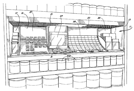
[0045] A display apparatus 11 according to an illustrative embodiment is shown
Figure 1. The apparatus 11 includes a cabinet 13 which mounts 5 display
modules, 17,
19, 21, 23, 25. In the illustrated embodiment, the modules 17, 19, 21, 23, 25
separately
mount into the cabinet 11 and therefore are subject to being reordered in any
desired
sequence.
4
CA 02527340 2005-11-18
[0046] The first and fifth display modules 17, 25 comprise brochure display
modules.
The first display module 17 presents brochures of a first size, while the
fifth display
module displays brochures of a second size. The size, of course, could be the
same or
different, as desired.
[0047] The second and fourth display modules 19, 23, mount respective concave
display panels 27, 28. The first display panel of 27 may provide a display of
a plurality
of wood chips to each of which has been applied a different water proofing
coating.
The second display panel 28 may present a display of a plurality of wood chips
each
stained with a different wood stain, which may be, for example, either a solid
and/or
semi-transparent stain.
[0048] The third display module 21 includes an interactive instructive video
display 29,
which may comprise a DVD/DVI (143, Fig. 26) player. The module 21 further
mounts a
display panel 31. The display panel 31 preferably mounts a plurality of
adjacently
disposed wood chips. Each of the chips comprises a different species of wood
to which
the same wood stain product has been applied. In this manner, a potential
customer
may appreciate the difference in overall appearance contributed by the
underlying wood
species.
[0049] A recessed fluorescent lighting fixture 27 is disposed above the
display
modules 17, 19, 21, 23, 25. As will be explained in more detail below, the
recessed
lighting fixture 27 is specially designed to provide optimum and uniform
illumination of
the samples displayed by the display panels 27, 28.
[0050] Figure 2 illustrates the display apparatus 11 and the modules 17, 19,
21, 23, 25
with various graphic display components removed. Each of these components 11,
17,
19, 21, 23, 25 of Figure 2 will be now described in more detail.
[0051] Figures 3 thru 5 illustrate the construction of the large brochure
module 25.
This module 25 includes first and second side panels, 33, each of which has a
bottom
edge 39 and back edge 38, which meet at right angles to one another. The front
edge
of each panel 33 is defined by a first vertical linear section 30, which meets
with a
convexly curved section 36, which then leads to a second vertical depending
section 32.
CA 02527340 2005-11-18
The vertical section 32 forms into a surface whose top edge 132 is disposed at
a slightly
acute angle to the horizontal. Thus, a vertical leg 34 and a horizontal foot
37 are
defined on each of the side panels 33. The side panels 33 are linked to one
another by
a back panel 35, a floor or base panel 47, and an upper horizontal panel 44.
The
module 25 further includes a central panel 45 having a convex outer edge 46,
which lies
in parallel with the respective convex edges 36 of the side panels 33. A hole
26 is
formed in the floor panel 47 through which a fastening device such as a screw
may be
inserted to fasten or attach the module 25 to an underlying shelf or other
structure.
[0052] Respective deck panels 41, 42 are disposed between the first side panel
33
and the central panel 45 and between the central panel 45 and the second side
panel
33, respectively. Clear vertical face panels 46, 48 are further mounted in
slots in the
respective side and central panels 33, 45. The face panels 46, 48 may
comprise, for
example, plexi-glass preferably anchored in place by a suitable adhesive. The
panels
33, 35, 47, 45 of the module 25 are preferably made of suitable wood or wood
substitute
materials fastened together according to conventional means well-known to
those
skilled in the woodworking arts.
[0053] Figures 6 and 7 further illustrate the cabinet 13, which mounts the
five modules
17, 19, 21, 23, 25. As shown, the cabinet 13 preferably includes identical
rectangular
vertically disposed end panels 51, 53, between which are mounted a horizontal
rectangular base "shelf' 56 and a vertical rectangular back panel 55. The back
panel 55
is inset from the back edge 58 of the base 56. Holes 57 are bored through base
portion
or shelf 56 behind the back panel 55 to facilitate water flow according to a
fire
prevention irrigation feature described in more detail hereafter.
[0054] Figures 8 and 9 further illustrate the third display module 21, which
mounts the
video monitor 29 (Fig. I). The module 21 includes first and second rectangular
vertical
side panels 61, 63 spaced apart by a width appropriate to mount the video
monitor 29.
The side panels 61, 63 further include horizontally extending display card
mounting
portions 67, 69 in which are formed suitably curved grooves 75 for receiving a
display
card as described in further, detail hereafter. The module 21 further
preferably includes
6
CA 02527340 2005-11-18
a horizontally disposed rib 73, which provides a support structure to
horizontally
stabilize the module 21. Again, the module 21 may be fabricated of suitable
wood or
wood substitutes according to techniques well-known to those in the
woodworking arts.
[0055] Figure 10 and 11 illustrate the fourth display module 23 in more
detail. The
fourth module 23 includes a rectangular base member 73, a vertical rectangular
back
panel 71 and respective vertical side panels 75, 77. The side panels 75, 77
each have
a horizontal bottom edge 76 and a vertical back edge 78. Each of the display
panels
75, 77 further has a concave outer edge 80, 82 and an interior concave groove,
e.g., 84,
for receiving the display panel 28. The respective interior grooves, e.g., 84,
are mirror
images of and lie parallel to one another.
[0056] The fourth display module 23 further includes first and second interior
support
panels 79, 81, each of which has a respective horizontal bottom edge, vertical
back
edge, and a concave surface 68, 69. The concave surfaces 68, 69 are parallel
to one
another and disposed in line with the grooves 84 so as to provide support to
the display
panel 28, after it has been inserted into the grooves 84, as described in more
detail
below. Finally, the bottom panel 73 of the module 23 includes a number of
water
drainage holes 86. These holes cooperate with the fire sprinkler water
distribution
system to be described in further detail below.
[0057] Figures 12 and 13 illustrate the second display card holding module 19
in more
detail. The module 19 includes first and second vertically disposed side
panels 91, 93,
each of which has a vertical back edge 94 and a horizontal bottom edge. 95.
Each of
the side panels 91, 93 further includes a concave outer edge 97, 99. Each
interior side
surface of each of the side panels 91, 93 includes a concave groove, e.g.,
101.
The grooves 101 are again mirror images of and disposed parallel to one
another.
The second display module 19 further includes a vertical, rectangular back
panel 90 and
a horizontal rectangular base panel 92. Again, suitable drainage holes 106 are
created
in the bottom panel 92.
[0058] Figures 14 and 15 illustrate the first display module 17 in more
detail. The first
display module 17 includes first and second side panels 101, 103 contoured
similarly to
7
CA 02527340 2005-11-18
those of the display module 25 of figures 3-5. Like module 25, the module 17
includes a
horizontal rectangular base panel 105 and vertical rectangular back panel 107.
The module 17 further includes a plurality of rectangular horizontal deck
members 109,
111, 113, disposed in step-like fashion with respect to one another. The
module 17
further includes a number of vertical transparent face plates 115, 117, 119,
120, which
may be, for example, disposed in suitable grooves in the side panels 101, 103
and
retained in place by a suitable adhesive. A hole 29 is formed in the base
panel 105
through which a fastening device such as a screw may be inserted to attach the
module
17 to an underlying shelf or other structure.
[0059] Figures 16 and 17 show an illustrative embodiment for a display panel
28
(Fig. 1 ) for insertion into the fourth display module 23. The panel 28 shown
in Figure 15
may comprise, for example, a rectangular panel of .125 millimeter thick
expanded PVC.
Illustrative dimensions of such a panel are 825.5 millimeters (32.5 inches) in
width (w)
and 590.55 millimeters (23.250 inches) in height (h). As further illustrated,
suitable
holes 113, which may be for example 166 in number, are punched or otherwise
created
in the panel 28 in order to attach sample mounting chips such as are
illustrated in
Figure 34. Figure 17 illustrates the graphic layout of sample chips 115 on the
panel 28.
During installation, the flat panel 15 is inserted into the curved slots in
the module and
thereby is effectively turned into a curved panel, which is more suitable to a
typical
consumer's line of sight and results in improved, light distribution and space
conservation.
[0060] Figures 18 thru 23 illustrate the recessed lighting fixture or "light
box" 27 of
Figure 1 in more detail. The fixture 27 includes a number of pairs of
fluorescent lamp
fixtures 123 disposed within a housing 124. Each lamp fixture 123 preferably
includes a
biaxial lamp unit, preferably a Philips PL-L55W, 55 watt, 5500 K, 92 CRI unit.
A CRI of
90 or above is preferred. The housing 124 comprises a perforated horizontal
mounting
(ceiling) panel 121, first and second rectangular vertical end members 125,
126 and a
rear edge member 127. Figure 19 illustrates a centered header attachment
support
134, and a rectangular reinforcement member 136, which member 136 preferably
extends the entire length of the light box 127. The header support 134 and
8
CA 02527340 2005-11-18
reinforcement member 136 serve to prevent sagging of the middle of the
structure.
The member 136 may, for example, be a metal tube or formed from a portion of a
metal
sheet used to fabricate panel 121.
[0061] Each fixture of the pair of lighting fixtures 123 is mounted parallel
to an
adjacent fixture 123 and at a slight acute angle to the horizontal edge 130 of
the
mounting panel 121. The acute angle may be for example eight (8) degrees. The
light
fixtures 123 are so arrayed as to create a uniform lighting effect on the
concave display
panels. As may be seen in Figure 22, the pairs of parallel light tubes of the
fixtures 123
lie horizontally and provide a substantially linear line of light-radiating,
surface.
[0062] Figure 20 shows a detail of a lamp fixture 123 and its associated
reflector 131.
A single side reflector 131 is positioned behind each lamp fixture 123. The
reflector 131
is especially designed with angled side sections 131, 135 in order to
appropriately direct
the light. Angled section 133 may be '/2" in length and formed at an angle of
130
degrees with respect to horizontal portion 126, which maybe 2.5 inches in
width.
Angled portion 135 may also be '/2" in length and formed at an angle of 160
degrees to
angled portion 135. The reflecting surface may be 95% reflective, 92%
specular.
The single side reflector 131 further directs light downwardly, preventing
glare in the
customer's eyes.
[0063] Figure 23 illustrates a decorative front face plate 129 which closes
the front of
the fixture 27 and is seen by one viewing the display 11. A diffuser grill 201
(Fig. 1 ) is
mounted at the bottom of the lamp fixture 27 and is further illustrated in
Figs. 23A and
23B. The diffuser may be a rectangular plastic grill ("egg crate" diffuser)
comprising
square openings each of which may be'/2 inch on a side.
[0064] The lamp mounting arrangement shown in Figure 18 positions a light
producing
lamp portion adjacent a "tombstone" lamp mounting receptacle. The light box 27
is
relatively shallow in depth and the staggered arrangement of light fixtures
123 together
with the diffuser 201 substantially eliminates dark spots and provides a
uniform,
customer-attracting and aesthetically pleasing light distribution.
9
CA 02527340 2005-11-18
[0065] Figures 24 and 25 illustrate an advantageous irrigation feature, which
cooperates with sprinkler systems positioned above the display 11 to
distribute the flow
of fire retarding water throughout the unit and to goods, e.g., 202 (Fig. 1 ),
stored
beneath the display 11. As may be seen, the perforations, e.g., 122, in the
light fixture
housing 121 cooperate with holes, e.g., 86, 186, in underlying module members
to
permit water flow down and throughout the display 11 and its modular
components 17,
19, 21, 23, 25. Holes 186 and 86 overlie matching holes, e.g., 57 in the
cabinet 13.
[0066] Figures 26 and 27 illustrate further details of the interactive video
module 21.
The module 21 encloses a video display monitor 29 which has a display viewing
screen
145 and user manipulated buttons 141. The buttons 141 permit a user to step
through
a menu of audio/video displays describing, for example, various tasks required
in
applying and selecting stains, waterproofing, and other products.
[0067] Figure 26 shows a cover plate 147 in a removed position, revealing a
DVD/DVI
player 143. The DVD or DVI player 143 may be an adaptation of a commercially
available unit providing a track selection feature cooperating with the
buttons 141.
Figure 27 further illustrates a display panel 151 partially inserted into the
concave
grooves 75 of the module 21. The display panel 151 may carry, for example,
four rows
of wood chips, e.g., 152, 151 selectively stained. Each of the chips 154 may
comprise a
different species of wood each stained with the same stain, thereby
illustrating to the
consumer the different effects which the underlying wood can have on the
finished
appearance of the stained wood.
[0068] Figures 28 thru 31 illustrate an apparatus and method for securing the
modules
17, 19, 21, 23 into the surrounding cabinet 13. In particular, a flat
horizontal panel 166,
preferably sheet metal, is provided with suitable parallel slots 163 and with
a front
molding piece 167 providing a vertically extending surface 170 for abutting
respective
noses 171 of the modules 17, 19, 21, 23, 25. A stud 165 is positioned in each
slot 163
and serves to position and guide the panel 166. The panel 166 is slideable in
and out
between the shelf 56 and the base panels 47, 71, 92, 73, 105 of the respective
modules
17, 19, 21, 23, 25, guided by the studs 165.
CA 02527340 2005-11-18
[0069] Considering Figures 29 and 30, in the order to secure the modules 17,
19, 21,
23 in place, the front molding piece 167 is pushed in towards the respective
noses 171
of the modules 17, 19, 21, 23, 25 until the position shown in Figure 30 is
reached, at
which point, screws or other devices are inserted through the holes 26, 29 in
the base of
each of modules 17, 25, then through the sheet metal panel 166, and finally
into the
shelf 56, thereby securely fixing the molding piece 167 and hence the modules
17, 19,
21, 23, 25 in position. Other means of securing the modules in place can of
course be
used. In one alternate embodiment, for example, a piano hinge could be used to
mount
a suitable front molding piece 167. It will also be noted further that the
placement of the
fastening devices through holes 26, 29 in the respective brochure modules 17,
25
renders them inconspicuous, for example, as compared to side insertion through
panel
13. Fig. 31 illustrates an alternate approach wherein a screw or other
fastening device
is inserted through a display panel, then through a module base and a sheet
metal
panel, and into the shelf 56. The approach using holes 26, 29 is preferred
over this
approach because it is less conspicuous.
[0070] Figures 32 through 37 illustrate a chip mounting mechanism 215. As
illustrated
in Figure 33, the chip mounting mechanism includes a removable chip holder
217,
which mounts into a carrier 225. Both the chip holder 217 and the carrier 225
may be
fabricated, for example, of a suitable molded plastic.
(0071] The chip holder 217 includes a base portion 232 on which is formed
first and
second horizontal tabs 229, 221 and an acutely angled tab 230. The chip holder
217
further includes vertically depending edge portions 235, 237 and respective
lips 239,
240 (Figure 35). Each lip 239, 240 has a cammed surface 350 to facilitate
installation
as further described below.
[0072] As illustrated in Figure 34, the tabs 229, 231, 230 facilitate
removable mounting
of respective wood chips 219, 221, each of which has a groove 227 formed
therein for
slideably receiving the respective tabs 229, 231. The opposite ends of the
respective
chips 219, 221 slide snuggly underneath the acutely angled tab 230.
11
CA 02527340 2005-11-18
[0073] The carrier member 225 includes a flat rectangular bottom 253 and a
generally
rectangular rim 251 formed about the periphery of the bottom 253. First and
second
slots 241, 243 are formed in the carrier member 225 for receiving the
respective tabs
239, 240 (Fig. 35) of the chip holder 217. The vertically depending edge
portions 235,
237 of the chip holder 217 are sized such that they snuggly fit within the
rectangular rim
251 of the carrier member 225. On the underside of the bottom 253 of the
carrier
member 225 are formed respective expandable plugs 250, which insert into
respective
adjacent mounting holes e.g., 261, 263 formed in the display panel 28.
[0074] Figures 35 through 37 illustrate the manner of insertion of the
removable chip
holder 217 into the carrier member 225. As shown, the first lip 239 is engaged
with the
first slot 241, and then the chip holder 217 is pressed downward such that the
second
lip 240 snaps into the slot 243 with the assistance of the cammed surface 350,
thereby
snuggly joining the chip holder 217 and carrier member 225 together. Suitable
wood
chips, e.g., 229 may then be slideably inserted into the chip carrier 217.
Thereafter, the
assembled unit may be mounted on the display panel 28 by inserting the prongs
250
through the respective mounting holes, e.g., 261, resulting in the mounted
position
shown in Figure 37. The construction illustrated in Figures 32-37 permits
sample chips
to be removed by the retailer (but not the customer) for purposes of changing
out or
updating different chips, as desired.
[0075] Those skilled in the art will appreciate that various adaptations and
modifications of the just-described preferred embodiment can be configured
without
departing from the scope and spirit of the invention. Therefore, it is to be
understood
that, within the scope of the appended claims, the invention may be practiced
other than
as specifically described herein.
12