Note: Descriptions are shown in the official language in which they were submitted.
CA 02527393 2005-11-21
SPRING SEAT ASSEMBLY
BACKGROUND OF THE INVENTION
1. Field of the Invention
[0001] The invention relates to an assembly for a suspension system of a
vehicle of the
type using a coil spring.
2. Description of the Prior Art
[0002] Vehicle suspension systems of the prior art typically include spring
seat
assemblies each having a pair of opposing spring seat retainers with a coil
spring
disposed therebetween. Spring seat retainers of a variety of configurations
are well
known in the art. An example of a configuration of a spring seat retainer is
shown in
European Publication No. 0 778 166 Bl. The spring seat retainer disclosed in
this European
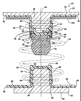
Publication is formed of a polymeric material and includes a flange extending
radially from
a central axis. A pocket portion extends axially from the flange to a distal
end and
supports a coil spring encircling the pocket portion. The pocket portion
includes a distal
rim and defines a cavity between the flange and the distal end. A jounce
bumper is
disposed within the cavity of the pocket portion and extends from the distal
end. The
design and material considerations of the spring seat retainer disclosed in
the European
Publication provides significant advantages over other prior art retainers.
[0003] During operation, the coil spring can be compressed to the point where
the jounce
bumper engages an opposing spring seat retainer to cause the jounce bumper to
compress
and exert forces radially outwardly against the distal rim. These radial
forces on the
distal rim can be large enough to cause the distal rim to deform or bulge,
especially if the
distal rim is made out of the polymeric material, i.e., plastic. The
functionality of the
1
CA 02527393 2005-11-21
spring seat retainer can be lost after the distal rim radially stretches and
permanently
deforms the cavity, which can cause the jounce bumper to fall out of the
cavity.
[0004] In addition, the European Publication discloses a spring isolator,
which is a pad
having a donut shaped configuration, abutting the flange of the spring seat
retainer. The
spring isolator is designed to absorb noise upon compression of the coil
spring. Spring
isolator pads of this type are useful, but can be cumbersome to install and
have
operational limitations.
[0005] Although the prior art has developed improved designs, there remains a
need to
develop a spring seat retainer that incorporates the advantages of the prior
art while avoiding
the potential drawbacks of the spring seat retainers and the isolator pads.
SUMMARY OF THE INVENTION AND ADVANTAGES
[0006] The present invention provides a spring seat assembly for use in a
suspension
system of a vehicle utilizing a coil spring. The spring seat assembly
comprises a spring
seat retainer having a flange extending radially from a central axis. A pocket
portion
extends axially from the flange to a distal end and supports a coil spring
encircling the
pocket portion. The pocket portion includes a distal rim and defines a cavity
between the
distal end and the flange for mounting a jounce bumper within the cavity. The
jounce
bumper extends from the distal end for compressing and exerting radial forces
within the
cavity against the distal rim upon a predetermined compression of the coil
spring. A
band encircles the distal rim of the pocket portion for preventing deformation
of the distal
rim under the band thereby retaining the jounce bumper in the cavity upon the
predetermined compression of the coil spring.
2
CA 02527393 2013-04-05
[0007] The present invention also provides a spring seat assembly comprising a
spring
seat retainer having a flange extending radially from a central axis. The
flange of the
spring seat retainer includes a first side and a second side extending
radially from the
central axis in a spaced and parallel relationship. A pocket portion extends
axially from
the flange to a distal end and defines a cavity between the distal end and the
flange. A
jounce bumper is mounted within the cavity and extends from the distal end. A
plurality
of ribs extend radially relative to the central axis, are spaced angularly
from one another,
and project axially from the first side and the second side of the flange to
dampen
vibrations and absorb noise.
[0008] The present invention further provides a spring seat assembly having a
restrictor for
preventing deformation of a distal rim to retain a jounce bumper. In addition,
the present
invention provides for a spring seat assembly having an integrated absorption
device that not only
dampens vibration and absorbs noise but is also cost effective and reduces the
number of parts.
The invention as claimed is however more specifically directed to a spring
seat assembly for
a suspension system of a vehicle utilizing a coil spring, said assembly
comprising:
a spring seat retainer having a flange extending radially form a central axis
and a pocket
portion extending axially form said flange to a distal end for encircling said
pocket portion, and
defining a distal rim and a cavity between said distal end and said flange;
a jounce bumper mounted to said pocket portion within said cavity and
extending from said
distal end for compressing and exerting radial forces within said cavity
against said distal rim upon
a predetermined compression of the coil spring, and
a restrictor at least partially disposed about said distal rim of said pocket
portion for
preventing bulging of said distal rim to retain said jounce bumper within said
cavity upon the
predetermined compressin of the coil spring, wherein a spring seat assembly
for a suspension
system of a vehicle utilizing a coil spring, said assembly comprising:
wherein said distal rim defines an inner surface and an outer surface with a
recess disposed
within said outer surface, and said restrictor being disposed within said
recess.
3
CA 02527393 2013-04-05
,
BRIEF DESCRIPTION OF THE DRAWINGS
[0009] Other advantages of the present invention will be readily appreciated,
as the same
becomes better understood by reference to the following detailed description
when considered in
connection with the accompanying drawings wherein:
[0010] Figure 1 is a cross-sectional view of a suspension system of a spring
seat assembly showing
a first spring seat retainer and a second spring seat retainer at opposite
ends of a coil spring
shown in phantom, ___________________________________________________________
3a
CA 02527393 2005-11-21
[0011] Figure 2 is a perspective view of the first spring seat retainer and
the coil spring
shown in phantom,
[0012] Figure 3 is an exploded view of the first spring seat retainer,
[0013] Figure 4 is a perspective view of the first spring seat retainer,
[0014] Figure 5 is a side view of the first spring seat retainer,
[0015] Figure 6 is a cross-sectional view of the suspension system in a
compressed state,
[0016] Figure 7 is a cross-sectional view of a second embodiment of a spring
seat
assembly showing a first spring seat retainer and a second spring seat
retainer at opposite
ends of a coil spring shown in phantom,
[0017] Figure 8 is a perspective view of the second embodiment of the first
spring seat
retainer and the coil spring shown in phantom, and
[0018] Figure 9 is an exploded view of the second embodiment of the first
spring seat
retainer.
DETAILED DESCRIPTION OF THE INVENTION
[0019] Referring to the Figures, wherein like numerals indicate corresponding
parts
throughout the several views, a spring seat assembly 20 is generally shown in
Figure 1.
The spring seat assembly 20 includes a first spring seat retainer 30 and a
second spring
seat retainer 32. The spring seat assembly 20 is part of a suspension system
for use in a
vehicle (not shown).
[0020] Referring to Figures 1 and 6, the suspension system further includes a
plurality of
spring seats 22 and a coil spring 24 shown in phantom. Each of the spring
seats 22
include a planar portion 26 and a projection 28 extending toward each other
from
4
CA 02527393 2005-11-21
corresponding planar portions 26. The spring seats 22 are preferably made of
steel and
are mounted to corresponding structures of the vehicle.
[0021] The first spring seat retainer 30 defines an opening 34 and the second
spring seat
retainer 32 defines a void 36 for mating with the corresponding projections 28
of the
spring seats 22. In particular, the first and second spring seat retainers 30,
32 are
mounted to associated spring seats 22 having the coil spring 24 disposed
therebetween.
One skilled in the art will appreciate that the first and second spring seat
retainers 30, 32
may be of any suitable configuration to mount to alternative spring seats 22
and/or
alternative suspension systems.
[0022] Referring also to Figures 2-5, the first spring seat retainer 30 is
shown having a
flange 40 extending radially from a central axis 38 to a peripheral edge 50. A
pocket
portion or neck 52 extends axially from the flange 40 to a distal end 54 for
supporting the
coil spring 24 encircling the pocket portion 52. Preferably, the flange 40 and
the pocket
portion 52 are formed of a homogeneous material. Even more preferably, the
first spring
seat retainer 30 may be formed of a polymeric material or plastic material
such as nylon,
isoprene, polypropylene, or polyurethane. In the most preferred embodiment,
the first
spring seat retainer 30 is formed of a one-piece integrated thermoplastic
polyurethane
(TPU) material.
[0023] A spring isolator 100 abuts the flange 40 of the first spring seat
retainer 30. The
spring isolator 100 preferably has a donut shaped configuration complementary
to the
configuration of the flange 40. The spring isolator 100 extends radially from
the pocket
portion 52 to the peripheral edge 50 of the flange 40. Preferably, the spring
isolator 100
is formed of an elastomeric material, such as micro-cellular polyurethane
(MPU).
CA 02527393 2005-11-21
[0024] The pocket portion 52 also includes a shoulder 58 and a plurality of
fins 60. The
plurality of fins 60 are spaced circumferentially about an exterior of the
pocket portion 52
and extend along the central axis 38 to the shoulder 58 for engaging and
retaining the coil
spring 24. The fins 60 extend axially from a predetermined distance spaced
from the
flange 40 to the shoulder 58. The fins 60 are preferably integral with the
pocket portion
52.
[0025] The pocket portion 52 further includes a distal rim 62, wherein the
distal rim 62
includes an inner surface 64 and an outer surface 66 in a spaced and parallel
relationship.
The outer surface 66 of the distal rim 62 defines a recess 68 extending
axially from the
shoulder 58 to the distal end 54. The pocket portion 52 also defines a cavity
56 between
the distal end 54 and the flange 40. The inner surface 64 of the distal rim 62
includes a
plurality of tabs 70 that project into the cavity 56. Preferably, the tabs 70
are integral
with the inner surface 64 of the distal rim 62. The first spring seat retainer
30 further
includes a stem 98 disposed within the cavity 56 of the pocket portion 52.
[0026] The distal rim 62 can undergo undesirable bulging and other deformation
from
heat and pressure. The subject invention therefore includes a restrictor at
least partially
disposed about the distal rim 62 of the pocket portion 52, which operates as
an anti-
bulging device for preventing bulging of the distal rim 62. The restrictor
preferably
includes a band 72 encircling the distal rim 62 for preventing bulging of the
distal rim 62
under the band 72. The band 72 is preferably continuous, presents spaced edges
74, and
disposed in the recess 68 with one of the edges 74 abutting the shoulder 58.
The distal
end 54 of the distal rim 62 includes a protrusion 76 that extends over one of
the edges 74
of the band 72 opposite the shoulder 58 to retain the band 72 in the recess
68. Hence, the
6
CA 02527393 2005-11-21
band 72 encircles the distal rim 62 of the pocket portion 52 for preventing
deformation of
the distal rim 62 under the band 72. The band 72 is preferably made of a
metal, such as
steel, and has a modulus of elasticity higher than the modulus of elasticity
of the
polymeric material of the pocket portion 52.
[0027] A jounce bumper 78 is disposed within the cavity 56 of the pocket
portion 52 and
extends from the distal end 54. The jounce bumper 78 will compress and exert
radial
forces within the cavity 56 against the distal rim 62 upon a predetermined
compression of
the coil spring 24. Preferably, the jounce bumper 78 is formed of a polymeric
or
elastomeric material, such as micro-cellular polyurethane (MPU). The jounce
bumper 78
defines an annular groove 80, wherein the tabs 70 of the distal rim 62 engage
the groove 80
for retaining the jounce bumper 78 within the cavity 56. As shown in Figure 1,
the jounce
bumper 78 presents a hollow 102 in the bottom thereof to define a skirt 104 in
which the
stem 98 of the pocket portion 52 engages the skirt 104 for forcing the jounce
bumper 78
radially outwardly toward the distal rim 62 and into engagement with the tabs
70.
[0028] As shown in Figure 6, the coil spring 24 can be compressed to the point
where the
jounce bumper 78 hits the second spring seat retainer 32 which causes the
jounce bumper
78 to compress and exert forces radially outwardly against the distal rim 62.
The band 72
resists any radial deflection of the distal rim 62 such that the tabs 70 of
the inner surface 64
of the distal rim 62 remain in continuous contact with the groove 80 to retain
the jounce
bumper 78 within the first spring seat retainer 30.
[0029] Referring back to Figures 1 and 6, the second spring seat retainer 32
has a similar
configuration as the first spring seat retainer 30. The second spring seat
retainer 32
includes a neck portion 88 and a base portion 82 extending radially from the
central axis
7
CA 02527393 2005-11-21
38 to an outer perimeter 84. The base portion 82 further includes a plurality
of ridges 86
spaced angularly from one another. The ridges 86 extend radially relative to
the central
axis 38 and project axially toward the outer perimeter 84 of the base portion
82. The
ridges 86 are spaced a predetermined distance from the neck portion 88 to
define a
depression 90 for engaging and retaining the coil spring 24. Preferably, the
ridges 86 are
integral with the base portion 82.
[0030] The neck portion 88 extends axially from the base portion 82 for
supporting the coil
spring 24 encircling the neck portion 88. The neck portion 88 includes a cap
92 at a top
thereof to define a jounce contact surface for engaging with the jounce bumper
78. A
plurality of strips 96 are spaced circumferentially about an exterior of the
neck portion 88
and extend along the central axis 38. The strips 96 are spaced a predetermined
distance
from the base portion 82 and extend toward a predetermined distance spaced
from the
jounce contact surface for engaging and retaining the coil spring 24.
Preferably, the cap 92
and the strips 96 are integral with the neck portion 88.
[0031] The base portion 82 and the neck portion 88 are preferably formed of a
one-piece
homogeneous material. Even more preferably, the second spring seat retainer 32
is similarly
formed of a polymeric material or plastic material such as nylon, isoprene,
polypropylene, or
polyurethane. In the most preferred embodiment, the second spring seat
retainer 32 is
similarly formed of a one-piece integrated TPU material..
[0032] Another embodiment of the spring seat assembly 220 is shown in Figures
7-9.
The spring seat assembly 220 includes a first spring seat retainer 230 and a
second spring
seat retainer 232. The spring seat assembly 220 is part of a suspension system
for use in
a vehicle (not shown).
8
CA 02527393 2005-11-21
[0033] Referring to Figure 7, the suspension system further includes a
plurality of spring
seats 222 and a coil spring 224 shown in phantom. Each of the spring seats 222
include a
planar portion 226 and a projection 228 extending toward each other from
corresponding
planar portions 226. The spring seats 222 are preferably made of steel and are
mounted
to corresponding structures of the vehicle.
[0034] The first spring seat retainer 230 defines an opening 234 and the
second spring
seat retainer 232 defines a void 236 for mating with the corresponding
projections 228 of
the spring seats 222. In particular, the first and second spring seat
retainers 230, 232 are
mounted to associated spring seats 222 having the coil spring 224 disposed
therebetween.
One skilled in the art will appreciate that the first and second spring seat
retainers 230,
232 may be of any suitable configuration to mount to alternative spring seats
222 and/or
alternative suspension systems.
[0035] Referring also to Figures 8 and 9, the first spring seat retainer 230
includes a
central axis 238, a flange 240, and a pocket portion 252. The flange 240
includes a first
side 246 and a second side 248 extending radially from the central axis 238 in
a spaced
and parallel relationship. The flange 240 also includes a plurality of ribs
244 that extend
radially relative to the central axis 238. The ribs 244 project axially from
the first and
second sides 246, 248 of the flange 240 and are spaced angularly from one
another. The
ribs 244 on the first side 246 are angularly offset from the ribs 244 on the
second side 248
for dampening vibration and absorbing noise upon a compression of the coil
spring 224.
The flange 240 further includes a peripheral edge 250, wherein the ribs 244 on
the first
and second sides 246, 248 of the flange 240 extend radially inwardly from the
peripheral
edge 250. Each of the ribs 244 on the first side 246 decrease in axial
thickness to taper
9
CA 02527393 2005-11-21
from the peripheral edge 250 toward the pocket portion 252. Similarly, each of
the ribs
244 on the second side 248 decrease in axial thickness to taper from the
peripheral edge
250 toward the opening 234. It should be appreciated that the ribs 244 may be
of any
suitable design or configuration so long as the flange 240 can adequately
dampen
vibration and absorb noise from the coil spring 224.
[0036] The pocket portion 252 includes a distal end 254 with the pocket
portion 252
extending axially from the flange 240 to the distal end 254 for supporting the
coil spring
224 encircling the pocket portion 252. Preferably, the flange 240, the ribs
244, and all
features of the pocket portion 252 are formed of a one-piece homogeneous
material.
Even more preferably, the first spring seat retainer 230 is formed of a
polymeric material
or plastic material such as nylon, isoprene, polypropylene, or polyurethane.
In the most
preferred embodiment, the first spring seat retainer 230 is formed of a one-
piece
integrated thermoplastic polyurethane (TPU) material.
[0037] The pocket portion 252 also includes a shoulder 258 and a plurality of
fins 260.
The plurality of fins 260 are spaced circumferentially about an exterior of
the pocket
portion 252 and extend along the central axis 238 to the shoulder 258 for
engaging and
retaining the coil spring 224. The fins 260 extend axially from a
predetermined distance
spaced from the flange 240 to the shoulder 258. The fins 260 are preferably
integral with
the pocket portion 252.
[0038] The pocket portion 252 further includes a distal rim 262, wherein the
distal rim
262 includes an inner surface 264 and an outer surface 266 in a spaced and
parallel
relationship. The outer surface 266 of the distal rim 262 defines a recess 268
extending
axially from the shoulder 258 to the distal end 254. The pocket portion 252
also defines a
CA 02527393 2005-11-21
cavity 256 between the distal end 254 and the flange 240. The inner surface
264 of the
distal rim 262 includes a plurality of tabs 270 that project into the cavity
256. Preferably,
the tabs 270 are integral with the inner surface 264 of the distal rim 262.
[0039] A restrictor 272 is disposed completely about the distal rim 262 to
prevent the
distal rim 262 from bulging or deforming. The restrictor 272 presents spaced
edges 274
and is disposed in the recess 268 with one of the edges 274 abutting the
shoulder 258.
The distal end 254 of the distal rim 262 includes a protrusion 276 that
extends over one
of the edges 274 of the restrictor 272 opposite the shoulder 258 to retain the
restrictor 272
in the recess 268. The restrictor 272 is preferably made of a metal, such as
steel.
[0040] A jounce bumper 278 is disposed within the cavity 256 of the pocket
portion 252
and extends from the distal end 254. Preferably, the jounce bumper 278 is
formed of a
polymeric or elastomeric material, such as micro-cellular polyurethane (MPU).
The jounce
bumper 278 defines an annular groove 280, wherein the tabs 270 of the distal
rim 262
engage the groove 280 for retaining the jounce bumper 278 in the cavity 256.
[0041] Referring back to Figure 7, the second spring seat retainer 232 has a
similar
configuration as the first spring seat retainer 230. The second spring seat
retainer 232
includes the central axis 238, a base portion 282, and a neck portion 288. The
base
portion 282 includes an outer perimeter 284, wherein the base portion 282
extends
radially from the central axis 238 to the outer perimeter 284. The base
portion 282
further includes a plurality of ridges 286 spaced angularly from one another.
The ridges
286 extend radially relative to the central axis 238 and project axially
toward the outer
perimeter 284 of the base portion 282. The ridges 286 are spaced a
predetermined
distance from the neck portion 288 to define a depression 290 for engaging and
retaining
11
CA 02527393 2005-11-21
the coil spring 224. Preferably, the ridges 286 are integral with the base
portion 282.
Although not numbered, the second spring seat retainer 232 may also include a
similar
rib configuration as discussed above for dampening vibration and absorbing
noise. In
particular, the base portion 282 of the second spring seat retainer 232 also
has a first side
and a second side extending radially from the central axis 238 of the second
spring seat
retainer 232 in a spaced and parallel relationship. The ribs would extend
radially relative
to the central axis 238 of the second spring seat retainer 232, be spaced
angularly from
one another, and would project axially from the first side and the second side
of the base
portion 282.
[0042] The neck portion 288 extends axially from the base portion 282 for
supporting the
coil spring 224 encircling the neck portion 288. The neck portion 288 includes
a cap 292 at
a top thereof to define a jounce contact surface for engaging with the jounce
bumper 278. A
plurality of strips 296 are spaced circumferentially about an exterior of the
neck portion 288
and extend along the central axis 238. The strips 296 are spaced a
predetermined distance
from the base portion 282 and extend toward a predetermined distance spaced
from the
jounce contact surface for engaging and retaining the coil spring 224.
Preferably, the cap
292 and the strips 296 are integral with the neck portion 288.
[0043] The base portion 282 and the neck portion 288 are preferably formed of
a one-piece
homogeneous material. Even more preferably, the second spring seat retainer
232 is
similarly formed of a polymeric material or plastic material such as nylon,
isoprene,
polypropylene, or polyurethane. In the most preferred embodiment, the second
spring seat
retainer 232 is similarly formed of a one-piece integrated TPU material.
12
CA 02527393 2012-05-24
[0044] It is worth mentioning that the scope of the claims should not be
limited by the preferred
embodiments set forth in the examples, but should be given the broadest
interpretation
consistent with the description as a whole.
13