Note: Descriptions are shown in the official language in which they were submitted.
CA 02527697 2005-11-25
WO 2005/000543 PCT/US2004/017734
ROLL CUTTING APPARATUS
BACKGROUND INFORMATION
FIELD OF THE INVENTION
[0001] The invention relates to the field of processing large rolls of sheet
material.
More particularly, the invention relates to cutting such large rolls. More
particularly yet,
the invention relates to sub-dividing an industrial-size roll of sheet
material into two or
more individual rolls.
DESCRIPTION OF THE PRIOR ART
[0002] Paper for the printing industry is provided on rolls of various widths.
Often,
it is necessary to re-size a roll from its original state, that is, to reduce
the width of the
roll, or to cut an end from a roll of paper that has been damaged. The
conventional
method of re-sizing such a roll is to run the paper through a rewinder. This
process
entails feeding the paper through a slitter that cuts the paper to the desired
width with a
blade, and rewinding the slit or cut material onto one or more rolls, as
applicable. One
of the largest industrial-size rolls of paper has a diameter of 72 inches and
a paper
width of 138 inches. Rolls this large are typically not re-sized on a
rewinder, because
the rewinder equipment for handling such large rolls would be extremely costly
and
space-consuming. Also, the rolls that require re-sizing are often not at a
facility that has
a rewinder. Because such rolls are extremely large, heavy, and difficult to
handle and
to transport, it is very costly and time-consuming to ship them to a facility
that does have
a rewinder. Thus, the rolls are generally re-sized on location, by cutting the
rolls with a
chain saw to the approximate size and then finishing the ends of the cut rolls
in a finish
or trim process. Because of the complexity and large number of components that
are
need in rewinding equipment, it is not feasible to construct a rewinder that
is a mobile
unit.
CA 02527697 2005-11-25
WO 2005/000543 PCT/US2004/017734
[0003] Special roll-cutting machinery is used to cut and re-finish industrial-
size
paper rolls. In U.S. Patent 6,269,719 B1, Easton et al. discloses machinery
that is used
to cut a roll into a narrower roll. The Easton et al. machinery provides a
horizontal bed
that supports a roll of paper and a rotary arm unit that includes a circular
saw. The saw
is mounted in such a way that it can be positioned along the roll only a few
inches in
from the end of the roll. Furthermore, the radius of the saw blade is small,
typically with
a 10-inch radius and, thus, much smaller than the radius of an industrial-size
roll. In
order for the saw to be able to cut across the cutting plane in toward the
center of the
roll, the material that has been cut must be removed rather quickly from the
roll. To
facilitate removal of this material, radial slices are cut into the end of the
roll with a chain
saw or a handheld circular saw to the approximate depth of the desired cut
before the
cut is made. As the saw cuts in from the outer perimeter, strips of the
trimmed waste
paper drop ofF or are pulled off and are discarded as waste paper and/or
recycled.
-[0004] U.S. Patent 5,964,024 (Wallace; 1999) discloses apparatus that
includes a
roll cutter that is similar in purpose to that of the Easton et al. roll-
cutting machine, but
with the roll of paper supported in a vertical position on a rotating base. As
with the
Easton et al. machinery, the saw is small, relative to the diameter of the
roll to be cut. A
second, hand-operated circular saw may be used to cut radial cuts into the end
of the
t
roll to a depth of the desired trim cut, so that the paper may be quickly
removed as the
saw travels inward toward the core. In this case, because the roll is
supported
vertically, spacers are inserted into the cut as the saw moves in toward the
core, to
prevent the upper part of the roll from slipping down and binding the saw. And
again, if
a wide roll of paper is to be divided into two or more rolls, a chain saw is
used to first cut
through the original roll at the approximate locations of the desired cut or
cuts and the
ends of each roll are then trimmed in separate operations.
[0005] Both the Easton et al. and Wallace equipment are provided as mobile
units.
That is, the roll-cutting machinery is mounted on a transport vehicle and
brought to the
2
CA 02527697 2005-11-25
,~ WO 2005/000543 PCT/US2004/017734
location of the rolls that are to be cut. Thus, the facility that processes
such rolls
collects and stores the rolls and, at intervals, calls upon the roll-cutting
service. This, of
course, requires space, roll-handling equipment, and administrative effort to
store and
keep track of the rolls, in order to determine when it is economically
feasible to hire the
roll-cutting service to come with the roll-cutting machinery and cut the
rolls.
[0006] The conventional roll-cutting machinery and methods of cutting, whether
the
rewinder operation or the cutting operations described above, have
disadvantages that
make it a difficult or costly process to reduce the width of a roll. The
rewinder method
requires sophisticated equipment that makes this method not practicable as a
mobile
unit, so that the owner that processes such large industrial size rolls must
either have
the rewinder equipment permanently installed to slit, or must ship the rolls
to a location
that provides that service. This, again, is very costly because of the
transportation
costs. Furthermore, it is critical that the rewinding be done properly, as
improperly
wound paper can dramatically change the physics of the originally manufactured
roll,
making it unusable for its intended purposes.
[0007] It is known in other industries to use a large circular saw blade to
cut
through a large cylindrical form of material. Saw blades used in the lumber
industry
come to mind. None of the known blades is capable of cutting through a large,
industrial-size roll of paper in a single-cut operation, leaving one or more
rolls with
smooth, finished, press-ready ends that require no further trimming or other
operations
to prepare them for subsequent processing.
[0008] What is needed, therefore, is machinery that efficiently cuts rolls in
a single-
cut operation and leaves a press-ready roll with a smooth, finished roll end
that requires
no further trimming or other end-finishing operations. What is further needed
is such
machinery that is capable of sub-dividing a roll into narrower rolls, with
little or no waste.
What is yet further needed is such machinery that accepts rolls in a wide
range of
widths and is adaptable to cut through a roll at virtually any location along
the width of
3
CA 02527697 2005-11-25
WO 2005/000543 PCT/US2004/017734
the roll.
BRIEF SUMMARY OF THE INVENTION
[0009] For the reasons cited above, it is an object of the present invention
to
provide saw apparatus that efficiently cuts rolls in a single-cut operation,
leaving a
press-ready roll with a smooth and finished roll end. It is a further object
to provide such
apparatus that is adaptable to subdivide a roll into narrower rolls,
generating little or no
waste. It is a yet further object to provide such apparatus that is adaptable
to accept
rolls in a-wide range of widths and to cut through a roll at any location
along the width of
the roll.
[0010] The objects of the invention are achieved by providing saw apparatus
that
is adapted to cut a roll to a particular size or to cut two or more rolls from
a wide roll.
Note that although the apparatus is described hereinafter as a saw for cutting
a paper
roll, the saw apparatus may be used for cutting rolls of various types of web
or sheet
material, such as plastic film, carpeting or flooring material, etc.
[0011] The saw apparatus according to the invention comprises a circular saw
for
cutting the roll, a load-bearing unit for holding the roll in position for
cutting, and roll-
placement means for placing the roll in the load-bearing unit. The circular
saw has a
radius sufficiently large to cut through an industrial-size paper roll,
without having to
remove cut material from the roll during the cutting operation, and is mounted
on a saw
frame that travels parallel to the load-bearing unit and is positionable for a
cutting
operation at any location along the width of a roll that is held in the load-
bearing unit.
Thus, the saw apparatus provides means for subdividing the roll into two or
more rolls of
virtually any desirable width.
[0012] For purposes of clarity in the subsequent descriptions, the footprint
of the
4
CA 02527697 2005-11-25
WO 2005/000543 PCT/US2004/017734
apparatus is defined as being substantially rectangular, with the narrow ends
of the
rectangle being referred to as a first end, which is a home position, and a
second end,
and with the sides of the rectangle being referred to as an entrance side and
an exit
side. The saw frame resides in the home position when not in use. The roll to
be cut is
brought to the apparatus on the entrance side, rotatably mounted in the load-
bearing
unit, and then discharged from the saw apparatus either to the entrance side
or the exit
side, depending on the particular roll-placement means incorporated into the
apparatus.
Generally, paper (or other sheet material) is wound around a hollow core to
form the
roll. The ends of the roll may be mounted directly on shaftless chucks in the
load-
bearing unit, or, a shaft, such as an air shaft with expandable lugs or
buttons, may first
be inserted into the hollow core of the roll and the shaft mounted in chucks.
The end of
the roll that is located toward the first end of the apparatus serves as a
reference
position for measuring an intended location of a cut.
[0013) The load-bearing unit comprises a rectangular load beam with two load
arms that are mounted on one face of the beam. The load beam has a length that
extends most of the distance between the first end and the second end of the
apparatus, with a first load-beam end being near the home position, a second
load-
beam end near the second end of the apparatus, and a longitudinal axis of the
load
beam extending therebetween. One or both of the load arms are slidably mounted
on
an adjustment mechanism that extends parallel to the longitudinal axis.
Depending on
the particular installation of the saw apparatus, one of the load arms may
instead be
fixedly mounted at the first load beam end, with the second load arm being
slidably
mounted. The distance between the load arms is adjustable by selectively
positioning
the slidably-mounted load arm or arms on the adjustment mechanism at a
distance that
will accommodate the specific length of the roll to be cut. A chuck is mounted
at the
upper end of each load arm.
[0014] The roll-placement means is used to place the roll of paper to be cut
in the
CA 02527697 2005-11-25
WO 2005/000543 PCT/US2004/017734
load-bearing unit. The invention encompasses several roll-placement means. A
first
roll-placement means includes a positioning assembly that rotates the load
beam into a
roll pick-up position and back into a cutting position. The positioning arms
are mounted
on the load beam, and as the arm rotates, the load beam is also rotated about
its
longitudinal axis. Extending from each end of the load beam, essentially
parallel and
co-axial to the longitudinal axis of the load beam, is a load journal that is
supported by
support bearings. Each journal supports a positioning assembly, which
comprises at
least one positioning cylinder, a lever arm, and at least one positioning arm.
The lever
arm is fixedly keyed to the journal and pivotably linked to the positioning
cylinder which
is connected to the positioning arm. Extending or retracting the piston on the
positioning cylinder causes the positioning arm to rotate about the journal,
which forces
the rectangular load beam to rotate about its longitudinal axis between the
roll pick-up
position, in which the load arms are in position for receiving and picking up
the roll, and
the cutting position, in which the load arms support the roll in position for
cutting.
Subsequent to the cutting operation, the roll-placement means is again
actuated to
rotate the load beam into the roll-pickup position, in order to release the
cut rolls from
the load-bearing unit.
[0015 A second roll-placement means includes a load table placed on the
entrance side of the load-bearing unit, an exit table on the exit side, a
height-adjustable
support bed or cradle mounted above and parallel to the load beam, and kicking
cylinders. With this embodiment of the roll-placement means, the load beam is
fixedly,
i.e., non-rotatably, mounted in the center of the rectangle of the saw
apparatus, parallel
to the entrance and exit sides. The load arms are height-adjustable, allowing
the
chucks at the ends of the load arms to be brought into position to receive
rolls of
different diameters. The support bed bears the weight of the paper roll while
the load
arms are brought into position to hold the ends of the rolls during cutting.
The kicking
cylinders are also height adjustable and are used to guide the roll from the
load table
onto the support bed and then onto the exit table.
6
CA 02527697 2005-11-25
WO 2005/000543 PCT/US2004/017734
[0016] The load arms serve to hold the roll in the proper longitudinal
position for
cutting, that is, they prevent the roll from shifting in a longitudinal
direction. Large
industrial-size paper rolls are extremely heavy and the support bed serves to
relieve the
load arms of the load and to maintain a horizontal alignment of the roll
during the cutting
process. Various means are suitable as the support bed. It is important that
the roll
rotate during the cutting operation; it is less critical whether the means of
rotation are
provided by the chucks or by rollers in the support bed. Ideally, the supports
on the
support bed are height-adjustable to guidingly support the roll of a
particular diameter
and to accommodate slight out-of-round conditions of the roll. The direction
of rotation
is generally in the same direction of rotation as that of,the saw blade at the
point of
contact of the saw blade. Depending on the type of material wound on the roll
and the
configuration of the saw blade, it may be desirable to have the roll rotate in
a direction
opposite to the direction of rotation of the saw at the point of contact.
[0017] The saw frame is mounted on the carriage rails and held in the home
position until the saw blade is to be positioned at some intended location of
cut between
the home position and the second load-beam end. It is within the scope of the
invention
to provide the saw frame as a tower in which the saw blade is supported at a
height
greater than the expected greatest diameter of a roll to be handled by the saw
apparatus, so that the saw blade, once positioned over the intended location
of cut, is
lowered into the roll. It is also within the scope of the invention to provide
the saw frame
as a floor frame in which the saw blade is supported laterally to the support
bed, with
the center of the blade parallel and at approximately the same height as the
longitudinal
axis of the roll shaft of the roll when held in the load arms. The saw blade
is then
moved in toward the core of the roll at the intended location of cut. Another
configuration of the saw unit includes installing the saw frame in'a pit
beneath the area
where the roll is supported in the cutting position, and raising the saw to
cut through the
roll. Still another embodiment of the apparatus according to the invention
provides a
saw frame that is stationary and a load-bearing unit that is mounted on a
carriage
7
CA 02527697 2005-11-25
WO 2005/000543 PCT/US2004/017734
system and positions the roll to be cut at an operating location of the saw
blade.
[0018] One danger of cutting material, particularly paper, is that the heat
caused
by the friction of the blade against the material is great enough to cause the
material
being removed to weld to the cutting surfaces of the saw blade or to the
material being
cut. The size of the saw blade used in the apparatus according to the
invention is so
great that the body of the saw blade serves as an effective heat sink, that
is, heat of
friction is rapidly absorbed away from the saw teeth into the body of the
blade and, as a
result, the saw blade remains cool. This reduces significantly the amount of
heat that is
transferred from the teeth to the material being cut, thereby reducing the
likelihood that
the material being removed will weld to the saw or to material on the roll.
Nevertheless,
depending on the type of material being cut, it may be desirable to provide a
lubricant-
coolant to the saw blade to cool the blade. A suitable coolant-lubricant is
ACCU-
LUBETM, manufactured by ACLU-LUBE Manufacturing GmbH. The lubricant is sprayed
as a fine mist onto the teeth at the top of the saw blade. The lubricant dries
as the
blade spins so that, by tfie time the teeth coated with the lubricant reach
the surface to
be cut, the lubricant has already dried and, thus, does not stain or damage
the material
being cut.
[0019] It is also within the scope of the invention to provide saw apparatus
that has
a support means, such as a support bed, mounted directly on the floor, which
allows the
roll to rotate during the cutting operation, but does not have the load-
bearing unit and
the roll-placement means described above. Rolls that are large in diameter,
but not
very long, are manageable with a conventional roll-handling truck, typically
referred to
as a clamp truck, that is used to pick up and transport rolls for short
distances. In this
scaled-down version of the saw apparatus, the carriage system for the saw
frame
extends alongside a support bed that has several long rollers on which the
roll is
rotatably supportable. For example, in a support bed having four long rollers,
one or
two of the long rollers are driven rollers, while the remaining long rollers
are follower
8
CA 02527697 2005-11-25
WO 2005/000543 PCT/US2004/017734
rollers.
[0020] Operation of the apparatus according to the invention is as follows: To
load
the. roll, it is placed alongside and parallel to the load beam, on the
entrance side of the
saw apparatus. If the first roll-placement means is used, the roll is placed
on the floor,
in position to be picked up by the load arms. Depending on the type of chucks
used,
shiftless chucks or conventional chucks for receiving a shaft, the roll is
either supported
on the noses of the shiftless chucks or a roll shaft is inserted into the
hollow core and
the ends of the roll shaft clamped between the two chucks. The positioning
assembly is
then actuated to force the load beam to rotate about its longitudinal axis
toward the
entrance side, so as to bring the upper ends of the load arms down to a
position that will
allow the ends of the roll shaft to be secured in chucks provided in the load
arms. The
positioning assembly is then actuated to force the load beam to rotate in the
opposite
direction, toward the back side of the apparatus, in which the roll is
positioned above the
support bed. If the support bed is fitted with height-adjustable supports,
these are
adjusted to guidingly support the roll of a particular diameter. The weight of
the roll is
born by the support bed, while the load arms, although providing some support
to the
roll, primarily maintain proper alignment of the roll. The nose on the
shiftless chucks or
the air shaft are fitted with expandable lugs or buttons which, when inflated
with air,
prevent the roll from shifting radially and/or longitudinally, which is
critical, as any
deflection would cause the saw blade to bind during the cutting operation and
would
result in gouging cuts in the edge of the roll.
(0021] If the second roll-placement means is used, the roll is placed on the
load
table and rolled onto the support bed, which is in its raised position. The
kicking
cylinders prevent the roll from rolling onto the exit table. The kicking
cylinders are then
actuated to guide the roll onto the support bed. Depending on the size and
weight of
the roll, the support bed, which is supported by hydraulic cylinders, may be
lowered to a
position in which the cylinders are fully retracted and resting on bearing
stops. The roll
9
CA 02527697 2005-11-25
WO 2005/000543 PCT/US2004/017734
is fitted onto the load-bearing unit as described above.
[0022] Once the roll is in the support bed and ready for cutting, the saw
frame is
moved along a carriage system until the saw blade is positioned at the
location of the
desired roll cut. The saw blade is driven through the rotating roll, including
through the
core, to completely sever a section of the roll from the rest of the roll. The
saw blade is
large enough to cut through a roll of industrial-size paper in a single-cut
operation,
leaving press-ready rolls with smooth ends that generally require no further
finishing.
Because the saw blade is positionable all along the length of the load beam, a
series of
cuts may be made in the roll, thereby subdividing the roll into multiple rolls
that are
ready for use. Depending on the roll-placement means employed, the cut rolls
are
either kicked out to the exit table or the load beam is rotated back to the
roll-pickup
position, in order to release the cut rolls onto the floor.
[0023] In the scaled-down version of the saw apparatus, the roll is placed on
the
support bed by the roll-handling truck, and the saw frame driven along the
carriage
system to the desired location of cut on the roll. The roll is rotated on the
support bed
during the cutting operation.
[0024) The ends of the paper rolls cut with the saw apparatus according to,
the
invention are very smooth and, in most cases, the roll is press-ready. In some
paper
processing operations, however, it may be desirable to have an extremely
smooth finish
on the ends of the cut paper rolls. In this case, a finishing station may be
provided,
either as a processing station that is integrated into the production line, or
as a separate
finishing station. The finishing station comprises a tower on which a sander
unit is
mounted. The lower half of the tower has a height-adjustable roll mounting
assembly
that includes a shaftless chuck for holding the cut paper roll. The sander
unit is height-
adjustably mounted in the upper half of the tower, and includes a sanding disc
and a
hydraulic motor. The cut roll is mounted on the chuck and raised off the
floor, and the
sander unit lowered so that the operative surface of the sanding disc is up
against the
CA 02527697 2005-11-25
WO 2005/000543 PCT/US2004/017734
face of the cut roll end. A depth adjustment means is provided on the sander
unit, for
adjusting the depth of material removal from the cut roll end.
BRIEF DESCRIPTION OF THE DRAWINGS
[0025] The present invention is described with reference to the accompanying
drawings. In the drawings, like reference numbers indicate identical or
functionally
similar elements.
[0026] FIG. 1 is a front view of the first embodiment of the saw apparatus
according to the invention.
[0027] FIG. 2 is an end view of the apparatus of FIG. 1, showing the saw
frame,
the support bed, and a side view of the load arm and positioning assembly.
[0028] FIG. 3 is a plane view of the carriage system.
(0029] FIG. 4 is an illustration of a conventional paper roll with a fiber
core. (Prior
Art)
[0030] FIG. 5 is an illustration of the load-bearing unit.
[0031] FIG. 6 is a front view of the positioning assembly.
[0032] FIG. 7 is a perspective rear view of the positioning assembly.
[0033] FIG. 8 is a top view of the support bed.
[0034] FIG. 9 is a front view of the second embodiment of the apparatus
according
to the invention, showing a floor frame to hold the saw blade.
[0035] FIG. 10 is an end view of the apparatus according to FIG. 9.
11
CA 02527697 2005-11-25
" WO 2005/000543 PCT/US2004/017734
[0036] FIG. 11 is a side view of a third embodiment of the apparatus according
to
the invention, showing the saw tower, the stationary load beam, and an
adjustable
support bed.
[0037] FIG. 12 is an end view of the embodiment of FIG. 11, showing the
configuration of load and exit tables.
[0038] FIG. 13 is a top view of the embodiment of FIG. 11, showing load and
exit
tables.
[0039] FIG. 14 is an illustration of a finishing station, shown from the
operator side.
[0040] FIG. 15 is an end view of the finishing station of FIG. 14.
[0041] FIG. 16 is an illustration of the sander unit.
[0042] FIG. 17 is a side view of the roll-lifting mechanism.
DETAILED DESCRIPTION OF THE INVENTION
[0043] FIGS. 1 and 2 illustrate a first embodiment of a saw apparatus 10
according
to the invention. The saw apparatus 10 comprises a saw unit 20, a carriage
system
110, a positioning assembly 40, and a load-bearing unit 70. For the sake of
illustration,
the operation of the saw apparatus 10 will be described hereinafter with
reference to
sawing through a roll 1 of paper, in order to re-size the roll. The roll 1, as
shown in FIG.
1, is a standard, industrial-sized paper roll having a roll diameter D of
approximately 50
inches and a roll width W of approximately 138 inches, although the saw
apparatus is
adaptable to processing rolls up to 72 inches in diameter. The saw apparatus
10
according to the invention may, of course, be used to cut or re-size smaller
rolls, and
indeed, generally may be used to cut very large and/or heavy cylindrical-
shaped
12
CA 02527697 2005-11-25
WO 2005/000543 PCT/US2004/017734
material, including rolls and fog-shaped material that lend itself to cutting
with a circular
saw blade.
[00.44] ~ FIG. 3 is a schematic illustration of the carriage system 110,
showing the
carriage rails 112 and a rack 114. As shown, the two parallel carriage rails
112
generally define a rectangular area that encompasses the saw unit 20. in the
embodiment shown, the saw unit 10 includes a frame 22 that is mounted on the
carriage rails 112 and moved along the rails carriage 112 by means of a drive
system
that is a rack-and-pinion assembly (only a rack 114 shown in FIG. 3) that is
connected
to the frame 22 and is driven by a motor 113 (shown in FIG. 1 ). The drive
system, with
motor, is well-known and is not discussed in any detail herein. Furthermore,
the
invention encompasses the use of other suitable means of driving the frame 22
along
the carriage rails 112.
[0045] For purposes of clarity, the footprint of the first embodiment of the
saw
apparatus 10 is also illustrated in FIG. 3. The upper end of the rectangle
that
encompasses the saw apparatus 10, which is also a home position of the saw
frame 20,
is referred to hereinafter as a first end 10A; the left-hand side of the
rectangle, i.e., to
the left of the load beam 72 (shown only schematically with dashed lines), is
referred to
as an operator side 10C; the opposite side of the load beam 72 is referred to
as a back
side 10D, and the lower, narrow end of the rectangle is referred to as a
second end 10~
of the saw apparatus 10.
[0046] Referring again to FIGS. 1 and 2, the saw unit 20 is shown in a home
position at the first end 10A of the saw apparatus 10. A saw blade 24 is
mounted on a
saw frame 27 that, in this first embodiment, is a tower frame. The saw blade
24 is
mounted on a platform that is movably supported on a plurality of ball screws
26. In the
embodiment shown, the saw blade 24 is a large blade with a radius of 32
inches, made
by Specialty Saw, Inc. of Simsbury, CT., and adapated to provide a press-ready
finish
on a cut end of the roll 3 in a single-pass cutting operation. A drive system,
such as an
13
CA 02527697 2005-11-25
" WO 2005/000543 PCT/US2004/017734
electric or a hydraulic motor, is used to drive the ball screws 26 to adjust
the height of
the platform, thereby controlling the height of the saw blade 24 and the
downward saw
feed rate. It is well-know to use drive systems with ball screws to control
feed' rate,
therefore the drive system is not shown or described in detail herein.
[0047] FIG. 4 (prior art) illustrates a roll 1 wound on a core 3. The core 3
in the
embodiments shown is a fiber core typically used with paper rolls. Shown in
FIGS. 1
and 2 are the load-bearing unit 70 and two positioning assemblies 40, one
positioning
assembly 40 mounted on each end of the load beam 72. A roll shaft 2 extends
through
the core 3 of the roll 1. Each end of the roll shaft 2 is rotatably mounted in
a safety
chuck 71 at the upper end of a load arm 73 and the two load arms 73 are
rigidly
mounted on a top face 72A of a rectangular load beam 72.
[0048] FIG. 5 shows the load-bearing unit 70 in greater detail. For purposes
of
illustration, the positioning assembly 40 is shown assembled at the first end
10A only of
the saw apparatus 10. One of the load arms 73 is an adjustable load arm 73A
and the
other one is a fixed load arm 73B. As shown, the adjustable load arm 73A is
mounted
on a threaded rod 76 that extends above the top face 72A of the load beam 72.
Also
shown in the fixed load arm 73B is the safety chuck 71. The adjustable load
arm 73A is
also equipped such a chuck. Conventional roll shafts are provided in a variety
of
standard lengths and the adjustable load arm 73A is positionable at any point
along the
threaded rod 76 in order to accommodate the length of the particular roll
shaft 2 being
used with the roll 1 to be cut. A hydraulic motor is used to position' the
adjustable load
arm 73A along the rod 76. Such means are well known in the field and are not
shown.
The load arms 73 securely hold the roll 1 in the proper position for measuring
a distance
from the end of the roll and for cutting by preventing the roll 1 from
shifting longitudinally
during the cutting operation. Any shift along the longitudinal axis of the
load beam 72,
even a minimal one, would cause the saw blade 24 to bind and would create a
ragged
end cut on the roll 1.
14
CA 02527697 2005-11-25
WO 2005/000543 PCT/US2004/017734
[0049) The journal 74 for mounting the beam-positioning assembly 70 is shown
in
FIG. 5 at one end of the load beam 72. Note that the journal 74 is keyed.
Another
similar journal 74 extends from the other end of the load beam 72. Each
journal 74 is
a
supported by a support bearing 42. One positioning assembly 40 is mounted on
each
journal 74. Refer to FIG. 1 for an overview of the positioning assemblies 40
in the saw
apparatus 10, each positioning assembly 40 comprising two positioning arms 44,
rotatably mounted on the journal 74 that extends from each end of the load
beam 72.
[0050) The positioning assembly 40 will next be described, with reference to
FIGS.
1, 3, and 5 - 7. FIG. 5 is an illustration of the load journal 74 on the load
beam 73 and
shows one of the positioning assemblies 40 mounted on the load beam. The load -
journal 74 is shown mounted on support bearings 42 and the beam-positioning
arms 44
mounted on the journal 74 so as to rotate freely about the journal 74. A lever
arm 45
(shown in FIG. 1 ) is keyed at one end to the journal 74 and linked at the
other end with
a first cylinder unit 47, which is pivotably linked to the beam-positioning
arms 44. A
second cylinder unit 48 is mounted on the floor on the back side of the
apparatus 10, as
shown in FIG. 7, and is rotatably linked to a bracket 50 that connects the
beam-
positioning arms 44. Actuating the first cylinder unit 47 assembly forces the
beam-
positioning arms 44 to rotate about an axis parallel and concentric with the
longitudinal
axis of the journal 74, between a roll-pickup position at the operator side
10C, shown in
FIG. 3, and an intermediate position, in which the load arms 73 are
substantially vertical
or tilted slightly toward the back side 10D. Actuating the second cylinder
unit 48
assembly forces the beam-positioning arms 44 to rotate the load beam 72 into a
cutting-
operation position, with the load arms 73 extending toward the back side 10D,
holding
the roll 1 reading for the sawing operation. The cylinder units 47 and 48 are
most
suitably hydraulically operated by conventional means, which are not shown
herein.
(0051) The load-bearing unit 70 with the load arms 73 provides a support means
for the roll 1. Because of the tremendous weight and/or the length of the roll
1, there is
CA 02527697 2005-11-25
WO 2005/000543 PCT/US2004/017734
a danger that the roll shaft 2 may deflect under the force of the sawing
operation. It
may be advisable then to provide a floor-mounted support means to relieve the
roll shaft
2 of the weight of the roll 1 as it is being cut. To this end, a support bed
130 is provided,
as shown in FIGS. 2 and 8. The embodiment of the support bed 130 shown has two
rows of supports 80. In the configuration shown in FIG. 2, the supports 80 are
angled in
toward the center of the support bed 130 to form an inversely V-shaped support
bed'
130. This configuration reduces the possibility that the weight of the roll 1
will cause the
supports 80 to deflect. It is critical that the roll rotate during cutting,
thus, a means of
rotation 82 is provided at the top of each row of supports 80. The means of
rotation 82
shown in FIG. 8 are a pair of long rollers 82A,82B, each roller of,which
extends
substantially the length of the support bed 130 and allows the roll 1 to,
rotate while being
supported by the support bed 130. The roll shaft 2 is rotatably driven in the
safety
chucks in the load arms 73 and the long rollers 82A,82B are free-rolling. In a
different
configuration, the roll shaft 2 is free-rolling within the safety chucks and
the means of
rotation 82 rotatably drive the roll 1 on the support bed 130. In this
configuration, one of
the long rollers 82A,82B is a driving roller and the other one a freely-
rotating roller. The
embodiment of the support bed 130 shown in FIG. 2 includes supports 80 that
are
adjustable in height and are pivotably mounted on the floor, so that they may
adjusted
to accommodate the diameter of the specific roll to be cut.
[0052] A second embodiment of a saw apparatus 100 according to the invention
is
shown in FIGS. 9 and 10. The primary difference between the first and second
embodiments is that the roll 1 is not cut from above, but from the side. The
load-
bearing unit 70, the positioning assemblies 40 and the support bed 130 are
essentially
the same as those described in the first embodiment. A modified saw frame 120
is
mounted on a carriage system 200 and travels alongside the roll 1 such that
the saw
blade 24 also travels alongside the roll. Ideally, the center of the saw blade
24 at a
height that is approximately the same as the center of the roll shaft 2.
Instead of
lowering the saw blade 24 from above into the roll 1, as is done in the first
embodiment
16
CA 02527697 2005-11-25
WO 2005/000543 PCT/US2004/017734
of the saw apparatus 10, the saw blade 24 is moved horizontally inward from
the side
toward the center of the roll 1.
[0053] FIG. 9 is an end view of the saw apparatus 100, showing the load beam
72,
the positioning assembly 40, the support bed 130, the carriage system 200, and
the
modified saw frame 120. The roll 1 is shown being lowered into position in the
support
bed 130. The modified saw frame 120 includes a threaded rod 126 that is
mounted in
the saw frame 120 such that it extends transverse to the longitudinal axis of
the roll 1.
Similar to the carriage system 100 shown in FIG. 3, the carriage system 200
includes
carriage rails 112 and a gear rack 114. The saw blade 24 is mounted on the
threaded
rod 126 and is drivable thereon in toward the roll 1.
[0054] The apparatus 100 may be equipped with auxiliary,,systems, such as a
lubricating system for cooling the blade and a dust-collection system for
collecting the
waste particles freed by the sawing operation. In tests conducted by the
Applicants, it
was found that the ACCU LUBETM lubricant, applied to the saw teeth by means of
a
spray system directed at the top of the blade, was already dry when the teeth
at the top
had rotated down to the cutting surface and that the blade was cool to the
touch. The
fact that the lubricant is dry before the treated teeth touch the material to
be cut reduces
the chances of the lubricant staining or damaging the material on the roll.
Because the
blade is so large; the rate of heat transfer away from the teeth into the body
of the saw
is extremely rapid, and, depending on the type of material being cut,
lubricant may not
be needed.
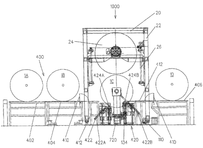
[0055] FIGS. 11 -13 show a third and preferred embodiment of a saw apparatus
1000 according to the invention. Saw apparatus 1000 comprises the saw unit 20,
and
the carriage system 110 described above, a load-bearing unit 700, a
loadinglunloading
means 400, and a roll-placement means 420. The loadinglunloading means 400
includes at least a load table 402 and an exit table 406. The load-bearing
unit 700
includes a load beam 720 and two load arms 730, each with a safety chuck 71.
The
17
CA 02527697 2005-11-25
WO 2005/000543 PCT/US2004/017734
safety chucks 71 may be either shaftless chucks that are sized appropriately
to receive
and securely hold the ends of the core 3, or chucks that receive and securely
hold a roll
shaft that is inserted in the core 3. The load beam 720 is similar to the load
beam 7.2
described above, but is stationary within the saw apparatus 1000 and does not
rotate.
The load arms 730 are mounted on the load beam 720. These arms are similar to
the
load arms 73, but are height-adjustable, allowing the safety chucks 71 to be
adjusted in
height to receive and hold the roll 1 when it is placed in the load-bearing
unit 700. In the
embodiment shown in FIGS. 11 -13, a second load arm 730B is slidably mounted
on
the threaded rod 76 that is mounted on the load beam 720 and the first load
arm 730A
is fixedly mounted on the load beam 720. It is, of course, possible to provide
a second
threaded rod 76 or other slide means for the first load arm 730A and to allow
both load
arms 730 to move along the load beam 720 to accommodate the width of the paper
roll
1.
[0056] The key differences between the first embodiment of the saw apparatus
10
and the preferred embodiment of the saw apparatus 1000 lie in the
loading/unloading
means 400 and the roll-placement means 420, shown in FIGS. 11 and 13. In this
preferred embodiment, the paper roll 1 is placed on the load table 402 and
rolled in the
direction of the load beam 720. The various positions of the paper roll 1 are
designated
1 A -1 D, as shown in FIG. 12. A weigh table 404 is provided as an optional
addition,
for weighing the paper roll 1 before it is processed. A hinged bridge section
410 bridges
the distance from the edge of the load table 402 or the weigh table 404 over
the
carriage system 110 to a support frame 412. The bridge section 410 is folded
up out of
the way once the paper roll 1 is situated in position 1 C in the load-bearing
unit 700, to
allow the saw unit 20 to travel on the carriage system 110 to the desired
position.
[0057] The roll-placement means 420 includes the support bed 130 with support
rollers 424 and kicking cylinders 422, as best seen in FIGS. 11 and 12. The
support
bed 130 is supported by hydraulically actuated support-bed cylinders 132 and
has has
18
CA 02527697 2005-11-25
WO 2005/000543 PCT/US2004/017734
two positions, a raised position at the top of the stroke of the hydraulic
support, and a
lowered position, in which the support-bed cylinders 132 are lowered onto
stops 134, to
relieve the load from the load arms 730 during the cutting operation. The
kicking
cylinders 422A and 422B and the support rollers 424A and 424B are shown in a
loading position, ready to receive the paper roll 1. The kicking cylinders
422A and the
support roller 424A are in a lowered position, and the kicking cylinders 422B
and the
support roller 424B in a raised position, a configuration which prevents the
paper roll 1 C
from rolling onto the exit table 406. Once the paper roll 1 has rolled free of
the entrance
table 402 or weigh table 404 and the support frame 412 and is in position 1 C,
the
kicking cylinders 422B and the support roller 424B are lowered. The paper roll
1 is now
resting on the support rollers 424 that allow the roll 1 to rotate. After the
cutting process
has been completed, the support rollers 424 and the kicking cylinders 422A are
raised
to kick the cut rolls out onto the exit table 406, shown as position 1 D,
whence they are
picked up by a clamp truck.
[0058] Most cut rolls are ready for use, without further processing. In some
cases,
however, extremely smooth ends are desired. It is within the scope of the
invention to
provide a finishing station 2000 that will sand the ends of cut paper rolls to
the desired
degree of smoothness. FIGS. 14 and 15 illustrate a portion of the finishing
station 2000,
comprising a sander unit 2100, a roll-lifting assembly 2200, fitted with a
shiftless chuck
2210 with a nose 2212, a finishing station tower frame 2300, and a finishing-
station
carriage system 2400. FIG. 16 shows details of the sander unit 2100 and FIG.
17,
details of the shiftless chuck 2210.
[0059] As shown in FIGS. 14 and 15, the tower frame 2300 is mounted on the
finishing-station carriage system 2400. Although only one tower frame 2300 is
shown, it
should be understood that a second tower frame 2300 may be mounted at the
opposite
end of the carriage system 2400. One or both of the tower frames 2300 travels
along
the carriage system 2400 to adjust the distance between the two roll-lifting
assemblies
19
CA 02527697 2005-11-25
WO 2005/000543 PCT/US2004/017734
2200 to receive and hold the cut paper roll 1 D. Alternatively, if the normal
paper-roll
processing will be post-treating relatively small cut rolls of paper, only one
tower frame
is required.
[0060] With continued reference to FIGS. 14 and 15, the sander unit 2100 is
mounted in the upper half of the tower frame 2300 and the roll-lifting
assembly 2200 in
the lower half. The sander unit 2100 is shown in two positions: a sanding
position, in
which the sander unit 2100 is located just above a shaftless chuck 2210 and,
in dashed
lines, in a home position, in which the sander unit 2100 is retracted to a
raised position,
The nose 2212 on the shaftless chuck 2210 is sized for insertion into the core
3 of the
cut paper roll 1 D and is provided with expandable lugs or buttons, which are
inflated to
ensure that the paper roll 1 D does not rotate relative to the nose 2212.
[0061] FIG. 16 shows details of the sander unit 2100, which includes a sanding
disc 2110, a handwheel 2140, a hydraulic motor 2120. The handwheel 2140 is
used to
adjust the amount of material that is to be removed from the end of the cut
paper roll
1 D.
[0062] FIG. 17 shows details of the roll-lifting assembly 2200. The shaftless
chuck
2210 is mounted on bearings on a hydraulic cylinder 2220, which is driven by a
hydraulic motor 2230. The nose 2212 is inserted into the core 3 of the cut
paper roll 1 D.
[0063] The scope of the invention encompasses a paper roll processing system
in
which the saw apparatus 100 or 1000 and the finishing station 2000 are
integrated into
a paper roll processing line. The cut paper roll 1 D, after being kicked out
onto the exit
table 406 is rolled into position before the roll-lifting assembly 2200, which
is adjusted in
height so that the nose 2212 is aligned with the core 3. The cut paper roll 1
D is then
mounted on the nose 2212 and the end of the roll sanded to the desired
smoothness
finish.
CA 02527697 2005-11-25
WO 2005/000543 PCT/US2004/017734
[0064 The detailed description of the invention includes descriptions of
specific
embodiments of the apparatus and the method of cutting a roll. It shall be
understood,
however, that a person skilled in the art is capable of implementing many
variations and
modifications of the invention without straying from the intended scope of the
present
invention as presented in the following claims.
21