Note: Descriptions are shown in the official language in which they were submitted.
CA 02527807 2005-11-29
WO 2005/021279 PCT/US2004/026955
METAL-BACKED PRINTING BLANKET
BACKGROUND OF THE INVENTION
This invention relates to a printing blanket construction, and more
particularly to a
metal backed printing blanket construction having a specialized corrosion
resistant treatment
that is attached to. the underside (or reverse) of the metal blanket. The type
of blanket
referred to herein is used primarily in offset lithographic printing, but may
also find utility
in other fields of printing.
In offset lithography, a rotary cylinder is covered with a printing plate that
normally
has a positive image area receptive to oil-based inks and repellent to water
and a
background area where the opposite is true. The pointing plate is rotated so
that its surface
contacts a second cylinder covexed with a rubber-surfaced ink-receptive
printing blanket.
The ink present on the image surface of the printing plate transfers, or
offsets, to the surface
of the blanket. Paper or other sheet stock to be printed is then passed
between the blanket-
covered cylinder and a rigid back-up cylinder to transfer the image from the
surface of the
blanket to the paper.
One common type ofprintingblanket is typicallymanufactured as a flat, fabric
sheet
with an elastomeric surface that is receptive to inlc. Such a blanket is
mounted by wrapping
it around the blanket cylinder. Various means are used to secure the blanket
to the cylinder.
Typically, the cylinder has a relatively wide gap or groove in its surface
(referred to herein
as "the cylinder gap"), running in the axial direction, and the leading and
trailing ends of the
printing blanket are inserted into the gap and secured by any one of a variety
of holding
devices. Such devices include reel rods and lock-up mechanisms (see, e.g.,
U.S. Pat. No.
1
CA 02527807 2005-11-29
WO 2005/021279 PCT/US2004/026955
4,870,901 to Norkus), bar supports (see, e.g., U.S. Pat. No. 4,092,923 to
Bolhner) and
clamps (see, e.g., U.S. Pat. No. 5,329,853 to Dining and Stegmeir) adapted to
grip the ends
of the blanket that are inserted into the cylinder gap. The leading and
trailing edges of such
blankets are generally reinforced with strips of metal, known as "blanket
bars", to stiffen
the blanket edges and to facilitate insertion of the blanket into the holding
device inside the
cylinder gap (see, e.g., U.S. Pat. No. 4,090,444 to Steams).
A metal-backed printing blanket typically comprises a base layer of a thin,
flat,
flexible sheet of metal and a top layer comprising an elastomer such as
rubber. Other layers
may be sandwiched between the base and top layers, formed of materials such as
fabric,
after which these multiple layers are laminated together. Such a blanket
conventionally has
a thickness of about 2 mm, of which about 0.20 mm may be attributed to the
thickness of
the metal base plate. One configuration of a metal-backed blanket manufactured
and sold
by I~BA (I~oenig & Bauer-Albert AG, of Franlcenthal, Germany) has a small
strip of
exposed metal at the leading and trailing edges of the blanket adapted for
insertion into the
cylinder gap. See, e.g., Puschnerat et al, U.S. Pat. Nos. 5,687,648 and
5,934,194. See also
Castelli et al, U.S. Pat. No. 5,749,298.
During the step in which the image is transferred from the plate to the
blanket and
the step where the image is transferred from the printing blanket to the
paper, it is important
to have intimate contact between the two contacting surfaces. This is
ordinarily achieved
by positioning the blanket-covered cylinder and the supporting cylinder it
contacts so that
there is a fixed interference between the two so that the blanket is
compressed throughout
the run to a fixed depth, typically approximately 0.002 to 0.006 inches. It is
important that
this compression be maintained uniformly over the entire surface of the
blanket.
Conventionally, this fixed interference is accomplished by inserting one or
more thin
layers of paper or the like between the blanket and the surface of the
cylinder to build up
2
CA 02527807 2005-11-29
WO 2005/021279 PCT/US2004/026955
the thickness of the blanket. This process is known as packing a blanket. This
process
presents problems however in that the packing procedure is time consuming,
resulting in
down time for the printing equipment. Further, once positioned on the
cylinder, the packing
paper tends to slide, slip, and/or fold which may render the blanket surface
nonunifonn and
resulting in poor printing results. Further, when a blanket must be replaced,
the time
consuming packing operation must be repeated for a new blanket.
So-called "no pack" blankets have been developed to provide a fixed
interference
without the need to pack the blanket. No pack blankets are manufactured to
very precise
gauges so that one can be installed directly onto a cylinder with the correct
amount of
interference. These blankets have the advantage of a one-piece construction
which requires
no positioning of packing paper beneath the blanket. This results in less down
time for the
printing equipment when an old blanket is removed and replaced with a new
blanket.
Such no pack blankets, like most printing blankets, are normally composed of a
base
material which gives the blanket dimensional stability. Presently most, if not
all,
commercial printing blankets use woven fabrics for the base material. The base
may consist
of one or more layers of such fabric. The working surface of the blanket which
contacts the
ink is typically an elastomeric layer of natural or synthetic rubber which is
applied over the
base layer or layers. The base layer or layers and working surface are
laminated together
using suitable adhesives.
In offset lithography as well as other printing operations, the printing plate
and
blanket cylinders are subject to corrosion and rust because of exposure to
inks, water, and
chemicals used in cleaning up the machinery. To combat such problems, these
cylinders
have typically been plated with chrome or nickel, as disclosed in U.S. Pat No.
5,366,799
issued to Pinkston et al. These metals provide a surface that is not only
corrosion resistant,
but also ink repellent.
3
CA 02527807 2005-11-29
WO 2005/021279 PCT/US2004/026955
However, such nickel- and chrome-plated cylinders have not worked well in
conjunction with no pack blankets. After only short periods of use, nickel is
removed from
the cylinder surface to such an extent that uncoated steel is exposed. While
chrome plating
is more resistant to removal than nickel, it too is subject to wear. The areas
on the cylinder
surface where the plated metal is removed are then subject to rapid corrosion
and/or
oxidation. Some have speculated that the nickel or chrome is'removed by
corrosion from
chemicals which wick around the edges of the printing blanket. Others have
speculated that
the metal removal is caused by electrical charges building up from the
friction between the
blanket and cylinder.
An alternative to using nickel- or chrome-plated cylinders is to coat the
printing
blanket or the cylinder surface with a plastic adhesive foil, such as
polyester. This is done
by gluing the adhesive foil to the cylinder's surface, or alternatively,
directly to the back of
the metal backed blanket. These adhesive foils have the many of the same
protective
characteristics of the metal plated cylinders, but do not experience the
degree of corrosion
and oxidation that the metal plates are subject to.
These adhesive foil coatings are not without problems. Exposure to the same
inks,
water, and chemicals that cause the corrosion/oxidation problems in the metal
plated
cylinders can cause bubbles to form between the polyester film, and the
surface of the
cylinder. These solvents penetrate the foil coating from either side of the
cylinder, resulting
in the bubbling and delamination of the foil coating.
An important goal in offset printing is to increase the operating speeds of
printing
presses in order to maximize production. However, flaws and imbalances in the
printing
blanket become magnified as the rotational speed of the blanket cylinder is
increased. In
particular, high-speed rotation of a cylinder with a cylinder gap can result
in undesirable
levels of vibration and shock loading. Bubbling and delaminating as described
above
4
CA 02527807 2005-11-29
WO 2005/021279 PCT/US2004/026955
causes the weight of the cylinder to be unevenly distributed about its axis.
The resultant
eccentric loading increases vibration during high-speed rotation of the
cylinder, to the
detriment of print quality. Fabric backed printing blankets are particularly
susceptible to
the deleterious effects of vibrations during high speed operations, such as
slipping and
smearing of ink as it is transferred from one surface to another.
Furthermore, high-speed operations increase shock loading, which occurs when
the
edges of the gap contact the adjoining printing plate. This repetitive impact
causes the
cylinder and the mounted blanket to bounce, causing the ink to streak and
increasing wear
on both the blanket and the cylinder.
Thus, it is desirable to create a coating for blanket cylinders that does not
experience
the drawbacks that are seen with the current plastic adhesive foils, or the
metal-plated
cylinders. Therefore, there exists a need in the art for a no-pac blanket that
can prevent
coiTOSion of the blanket cylinder without resulting in lengthy downtime of the
machine, or
a drop off in the print quality due to bubble formation.
SUMMARY OF THE INVENTION
The above-identified problems have been solved by eliminating the plastic
adhesive
foil and other packing of the metal backed blanket. Cleaning solvents and
other commonly
used printing chemicals do not form bubbles underneath the printing blanket
when the
blanket is applied directly to the blanket cylinder. To prevent the corrosion
that would
otherwise take place, the blanket cylinder contact surface of the metal backed
blanket is
specially treated. This treatment takes the place of the packing in the
prevention of slippage
of the belt around the drum, and also prevents corrosion of the drum due to
application of
the solvents, adhesives, and other chemicals. Unlike the packing materials of
the prior art,
5
CA 02527807 2005-11-29
WO 2005/021279 PCT/US2004/026955
the special backside treatment of the current invention does not bubble when
it comes in
contact with the adhesives and solvents that are used in the.application of
the metal-backed
blanket to the drum. Pretreating the metal backed blanket with the specialized
treatment
reduces the downtime, and the complexity of replacing the.printing blanket.
The specialized treatment applied to the metal backed blanket can be a very
thin
plastic film. The film is applied to the metal backed blanket in such a manner
as to pr event
the absorption of adhesives, solvents, and other printing chemicals by the
metal backed
blanket. This can be accomplished by thermowelding, plastic spray on
techniques, plasma
treatment, or any other method that is known in the art. The film is generally
applied in a
thickness of from 5 to 250 Vim, preferably from 5 to 100 ~,m, and optimally
from 25 to 100
~,m. The plastic adhesive foil can be made from such materials as polyolefins,
polyesters,
polyurethanes, phenolic compounds, polyethylene, polystyrene, polypropylene,
polymethyl
methacrylat,e polyamides, nylon, polyvinyl chloride, polyvinyl fluoride, or
the like.
When the specialized coating is therinowelded to the metal backed blanket, the
foil
prefereably has a thickness of from 10 to 250 ~,m. The theunowelded foil is
preferably
comprised of polyurethane, polyolefm, phenolic compounds, nylon, polyvinyl
chloride,
polyvinyl fluoride and the like.
When the specialized coating is applied by coating or spraying a film of
solvent and
abrasion resistant material, the coating has a preferred thickness of from 5
to 50 ~,m. The
spray on film is preferably comprised of polyvinyl fluoride (PVF),
polytetrafluoroethylene
(PTFE), polytetraethylene (PTE), epoxy resins, phenolic resins, and nylon
resins.
Finally, the specialized treatment can be applied by way of plasma treating
the metal
backed blanket with silicon carbide or aluminum oxide. In this embodiment, the
treatment
is applied to a thickness of from 5 to 25 ~,m.
6
CA 02527807 2005-11-29
WO 2005/021279 PCT/US2004/026955
Even though there is no longer and packing material, the total metal backed
blanket
thickness remains in the range of from 1.40 to 2.30 mm. This is beneficial,
since the
preferred blanket thicknesses for commercial presses are 1.65 to 2.15 mm, and
prefeiTed
blanket thicknesses are from 1.65 to 2.30 rtnn for newspaper presses.
BRIEF DESCRIPTION OF THE DRAWINGS
The present invention will be more readily understood by reference to the
accompanying drawing figures that represent three different possible blanket
structures and
the orientation of the compressible layer relative to the other layers which
are provided by
way of non-limiting example and in which:
Figure 1 is a top view of the invented printing blanket lying completely flat.
Figure 2 is an enlarged cross-sectional view of a metal backed blanket
according to
the invention, taken along section line 2 - 2 of Figure 1. The compressible
layer could be
placed close to the metal adhesive layer with two fabric layers close together
just under the
printing face.
Figure 3 is an enlarged cross-sectional view of a metal backed blanket in
accordance
with a preferred embodiment of the present invention. The position of the
compressible
layer could also be close to the adhesive layer (close to the metal) and
between the first and
the second fabric layers.
Figure 4 is an enlarged cross-sectional view of a metal backed blanket in
accordance
with another embodiment of the present invention. The position of the
compressible layer
7
CA 02527807 2005-11-29
WO 2005/021279 PCT/US2004/026955
could also be close to the adhesive layer (printing face) and between the
second and the
third fabric layers.
Figure 5 is a schematic view of the printing blanket mounted on a cylinder
having
a cylinder gap.
Figure 6 is an enlarged cross-sectional detail view of a portion of Figure 5
showing
the leading and trailing edges of the printing blanket inserted into the
cylinder gap.
DETAILED DESCRIPTION OF THE PREFERRED EMBODIMENTS
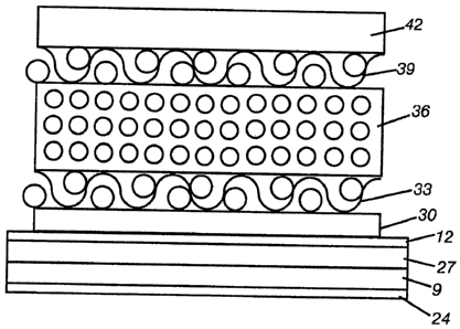
Figure 1 illustrates an embodiment of a printing blanket 3 of the present
invention,
which shows generally the compressible printing blanket 6, an anti-slip layer
12, and a
terminal portion 21 of a metal base plate 9 with a specialized coating layer
(shown in
Figures 2 through 4) applied to the backside thereof, lying in a flattened
position. For
convenience of understanding the invention, Figures 2 through 4 provide
greatly
exaggerated cross-sectional views of the printing blanket 3 showing the
different layers of
a preferred embodiment of the invention. These layers, together with their
associated
features, are discussed below.
For purposes of the present discussion, the terms "bottom" and "lower" and the
like
are used to refer to that portion of an individual layer or set of layers that
is most nearly
adjacent to the cylinder upon which the blanket of the present invention is
mounted.
Conversely, the "top" or "upper" portion of an individual layer or set of
layers is that portion
thereof which is located or positioned furthest from the printing cylinder.
8
CA 02527807 2005-11-29
WO 2005/021279 PCT/US2004/026955
The lowermost layer of printing blanket 3 is the metal base plate 9, which is
formed
of thin sheet metal that has been cut in a rectangular shape from a roll of
metal. The
thickness of the base plate is preferably from 0.05 mm to 1 mm, and most
preferably about
0.2 mm to ensure sufficient flexibility. Although stainless steel is a
preferred metal for the
base plate for purposes of fatigue resistance, high elastic modulus, etc., the
invention is not
limited to the use of stainless steel for forming the metal base plate 9.
The specialized coating layer 24 is attached to the bottom of the metal base
plate 9.
When the specialized coating layer 24 is thernowelded to the metal base plate
9, the
specialized coating layer 24 preferably has a thickness of from 10 to 250 ~.m.
The
specialized coating layer 24 is generally a thernowelded foil, preferably
comprised of
polyurethane, polyolefin, phenolic compounds, nylon, polyvinyl chloride,
polyvinyl fluoride
and mixtures thereof. When the specialized coating layer 24 is applied by
coating or
spraying a film of solvent and abrasion resistant material, the specialized
coating layer 24
has a preferred thickness of from 5 to 50 ~,m. The spray on film is preferably
comprised of
at least one ofpolyvinyl fluoride (PVF), polytetrafluoroethylene (PTFE),
polytetraethylene
(PTE), epoxy resins, phenolic resins, and nylon resins. Finally, the
specialized coating layer
24 can be applied by plasma treating the metal base plate 9 with silicon
carbide or
aluminum oxide, or a mixture of them. In this embodiment, the specialized
coating layer
24 is applied to a thickness of from 5 to 25 ~,m.
In a preferred embodiment of the invention, the metal base plate 9 is at least
partially
coated with a primer layer 27 that facilitates bonding of the metal base plate
9 to the
underside of the compressible printing blanket 6. Before primer layer 27 is
applied to metal
base plate 9, the top surface of the metal base plate 9 should be cleaned and
polished to
make the metal flat and to remove grease and oxides for better adhesion. The
primer should
be a material that is capable of adhering to metal and fabrics. A variety of
such materials
are well known to those of ordinary skill in this field. A nonlimiting example
of a primer
9
CA 02527807 2005-11-29
WO 2005/021279 PCT/US2004/026955
that has been found to be particularly useful on base plate is CILBOND 11,
produced by
Compounding Ingredients Limited, of Preston, England.
The cross-sectional view of Figure 2 shows the anti-slip layer 12 above the
primer
layer 27 on metal base plate 9. The metal base plate 9 has a coefficient of
friction that
would be well known to one of ordinary skill, depending on the metal used. The
anti-slip
layer 12 has a higher coefficient of friction than that of the metal and is
preferably a
compounded nitrite rubber. Alternative materials, including other elastomers,
may be used
for the anti-slip layer 12 as long as they are capable of increasing the
coefficient of friction
of the top surface of the blancet's leading and/or trailing edges 15 and 18.
Moreover,
because solvents typically are used to clean printing machinery, the anti-slip
layer 12 should
be solvent-resistant to maintain friction characteristics.
Anti-slip layer 12 is preferably formed after the compressible printing
blanket 6 has
been bonded to metal base plate 9 with primer layer 27 and adhesive layer 30.
In this
preferred embodiment after substantially all of the top surface of the metal
base plate 9 is
covered with the compressible printing blanket 6, the leading and trailing
edges 15 and 18
of blanket are ground down through at least part of the adhesive that binds
blanket 6 and
base plate 9 together. Thus, when anti-slip layer 12 is formed in this manner,
it comprises
a portion of adhesive layer 30, as well as, optionally, some of primer layer
27 as illustrated
in Figure 2. Alternative methods of forming the anti-slip layer 12 are
described below.
Adhesive shown in Figure 2 bonds the compressible printing blanket 6 or
"carcass"
to the metal base plate 9. As noted above, the adhesive layer 30 may be ground
down to
form anti-slip layer 12 and is preferably a compounded nitrite rubber, but
other elastomers
may be used in place of nitrite rubber, such as acrylic, urethane, neoprene
and fluorocarbon
elastomers, if desired.
CA 02527807 2005-11-29
WO 2005/021279 PCT/US2004/026955
In a preferred embodiment of the invention, fabric layer 33 forms the
lowermost ply
and fabric layer 39 form the uppermost ply of the compressible printing
blanket 6. Fabric
layer 33 is preferred as a means of reducing shear stresses that develop at
the interface
between the compressible printing blanket 6 and metal base plate 9. Shear
stresses arise
during operation of the press because the printing blanket is compressed at
the nip or print
zone between the blanket cylinder and the rigid plate cylinder. At the center
of the nip, the
blanket is depressed by the cylindrical contour of the printing plate. In the
proximate
vicinity of the nip, a bulge tends to arise in the printing blanket.
Compressible layers have
been developed for use in such blankets which minimize the bulges that occur.
Nevertheless, bulging and depression of the blanket in the print zone, when
present, result
in expansion and compression of the printing blanket. Such compression and
expansion
cause shear stresses at the interface between the printing blanket and the
base plate, because
the blanket's compressible layer is far more elastic than the metal base
plate. Shear stresses
have a tendency to cause the printing blanket to delaminate fr0111 the metal
base plate.
Fabric layer 33 reduces this tendency. The embodiment described herein, having
one fabric
layer 33 below the compressible layer, should not be viewed as limiting the
invention since
additional fabric layers may be incorporated at this location if desired for a
particular
application.
Fabric layer 33 may be forned of natural or synthetic material or may be a
natural/synthetic blend of an appropriate length and thickness (also referred
to as "gauge").
Cotton, polyester, nylon and rayon are typical materials that are commonly
used in fabric
. layers of printing blankets. The thickness of fabric layer 33 ranges from
approximately 0.1
mm to 0.4 mm and is most preferably approximately 0.2 mm.
Fabric layer 33, as shown in Figure 2, abuts a compressible layer 36 which
enables
the blanket to compress under pressure exerted at the two areas where the
printing cylinder
and impression cylinder contact the printing blanket 3, to prevent bulging and
thus to
11
CA 02527807 2005-11-29
WO 2005/021279 PCT/US2004/026955
enhance print quality. Compressible layer 36 comprises a plurality of cells
embedded in a
binder. Such cells resist the greater and more permanent deformation within
blanket that
would occur in the absence of such a layer. The binder in which the cells are
embedded is
made from a suitable resilient polymer matrix, into which a quantity of cell-
forming
materials are evenly dispersed to form a compound. The cells may be open,
e.g., formed
by salt leaching; or they may be closed, e.g., formed with the use of, e.g.,
blowing agents .
or microspheres. Microspheres, which are the preferred cell-forming material
for use in the
present invention, are dispersed relatively uniformly throughout the matrix
material such
that, upon application of the matrix to fabric layer 33, the microspheres
become thoroughly
embedded in the interstices of the fabric.
Generally, the microspheres are formed from materials such as, e.g.,
thermoplastic
resins, thermosetting resins, ceramics, glass and sintered metals. A pr
eferred thermosetting
resin for forming the microspheres used in the invention is a phenolic resin
having a density
of from about 0.01 to about 0.0~ grams per cubic centimeter. The microspheres
range in
diameter from about 1 to 200 microns, and preferably about SO to 130 microns,
with an
average size of about 90 microns being most preferred.
Generally, the microspheres are uniformly distributed throughout the elastomer
in
such a way as to avoid any appreciable crushing of the microspheres.
Additionally, the
microspheres are incorporated in the elastomeric material at a loading of
about 4-90% and
preferably 10-70% of the solids content. This percentage will vary based on
such factors
as microsphere dimension, wall thickness and bulk density, or if blowing
agents are
additionally incorporated within the matrix.
To form the cells in the embodiment described above, any of a wide variety of
microspheres can be added to a solution or dispersion of the matrix. If
solvent solutions are
utilized, the selected microspheres must ~be resistant to chemical attack from
the solvents.
12
CA 02527807 2005-11-29
WO 2005/021279 PCT/US2004/026955
Several acceptable types of thermoplastic microspheres useful with the present
invention are marketed, for example, by Expancel and Pierce & Stevens.
Microspheres of
a thermoplastic resin are preferred for this embodiment.
Figures 3 and 4 each show alternative embodiments of the present invention
utilizing
additional fabric layers that can be added to increase the blanket's overall
thickness, or to
decrease the shear stresses~that are experienced by a given part of the
blanket. In Figure 3,
the additional fabric layer 45 can be seen between the upper printing face 42
and the
compressible layer 36. Positioning a second fabric layer in this orientation
can decrease the
shear stresses between the printing face and the compressible layer. The
additional fabric
layer is bound to the upper fabric layer 39 by an adhesive layer 48.
Figure 4 shows an alternative embodiment where an additional fabric layer 51
is
inserted between the metal base plate 9 and the compressible layer 36. This
additional
fabric layer 51 is provided to decrease the shear forces between the base
plate 9 and the
compressible layer 36. The additional fabric layer 51 is bound to the lower
fabric layer 33
by an adhesive layer 54.
In the embodiments of Figures 3 and 4, an adhesive (not indicated in the
drawings)
is provided between compressible layer 36 and fabric layer 33. Adhesive may be
applied
to either or both compressible layer 36 and fabric layer 33 before these
layers are laminated
together. Alternatively or additionally this bonding may be effected by a
chemical reaction
that occurs between compressible layer 36 and fabric layer 33 during the
curing process.
The adhesive is typically nitrile rubber, as described above.
The embodiment of Figure 3 has one or more fabric layers such as fabric layers
39
and 45 positioned between compressible layer 36 and the printing face 42. This
top fabric
13
CA 02527807 2005-11-29
WO 2005/021279 PCT/US2004/026955
layer or fabric layer stack serves to stabilize the interface between
compressible layer 36
and upper printing face 42 during printing operations. Upper printing face 42
is an
etastomeric compound which is adapted to accept the print image from the
printing plate
and transfer it to a substrate such as paper. Upper face 44 of upper printing
face 42 may be
buffed to a desired surface roughness profile in a known manner to improve
print quality
and to facilitate release of the web.
To make the printing blanket 3 according to a preferred mode of the invention,
the
fabric layer 33 is first coated by spreading with an elastomeric compound such
as nitrite
rubber to bond compressible layer 36 atop fabric layer. The elastomer coated
fabric is cured
according to conventional methods, such as festooning, and is then buffed or
ground to a
desired thickness from 0.5 mm to 1.0 mm, preferably from 0.6 mm to 0.7 mm, and
optimally about 0.66 mm. Adhesive, e.g., nitrite rubber, may be spread over
the top of
compressible layer 36 to adhere an additional fabric layer. Additional
adhesive (e.g., nitrite
rubber) is spread on the bottom surface of another layer of fabric, which is
laminated on top
of compressible layer 36. Elastomeric printing face 42 is applied to the top
of the carcass,
which is then cured and ground again, so that the thickness of upper face
ranges from
approximately 0.2 mm to 0.5 mm, preferably 0.3 mm to 0.4 mm and most
preferably about
0.35 mm thick. The bottom of the carcass, after curing, is spread with nitrite
rubber
adhesive 30 to facilitate attachment to the metal base plate 9 through the
primer layer 27
placed thereupon.
Meanwhile, metal base plate 9 is cut to the desired dimensions and polished on
its
upper surface to remove oxides and grease. The top surface is coated with a
primer that aids
in bonding metal to etastomeric material. Metal plate 9 is then pressed or
laminated onto
the prepared carcass of compressible printing blanket 6. The preferred
thickness of the
entire blanket ranges from approximately 1 mm to 3 mm, more preferably 1 mm to
2 mm
and optimally about 1.61 mm.
14
CA 02527807 2005-11-29
WO 2005/021279 PCT/US2004/026955
To form anti-slip layer 12 according to a preferred mode of the invention, the
edges
of compressible printing blanket 6 near leading and trailing edges 15 and 18
and of metal
base plate 9 are ground down until a very thin layer of cured adhesive remains
on the
leading and trailing edges 15 and 18. In an alternative embodiment, however,
the leading
and trailing edges 15 and 18 of metal base plate 9 may initially be left bare.
Anti-slip layer
12 may thereafter be added to the exposed metal edges, e.g., by spraying or
brushing onto
the edges, optionally with an adhesive, after the carcass and metal base plate
9 are laminated
together.
Turning to Figure 3, in a further embodiment, sealant 66 is applied along the
edges
of blanket between the blanket and bare edge to keep various fluids such as
ink, water and
solvents typically encountered in a printing environment from penetrating the
multiple
layers of the blanket and causing swelling and delamination of the various
layers. The
sealant 66 should be resistant to such solvents, including those used for
cleaning the blanket,
and is preferably a nitrite polymer such as EC 776, produced by 3M. Other
materials that
may be used as sealants 66 include but are not limited to acrylic polymers,
fluorocarbon
polymers, urethane polymers, cyanoacrylate polymers, epoxy polymers or other
solvent-
resistant polymers and mixtures thereof.
Terminal portions 21 of printing blanket 3 are preferably formed by covering
the
ends of the edges with adhesive tape before primer is applied to the upper
surface of the
metal plate. The tape prevents primer from coating the sides andlor bottom of
the plate
during application of the primer. The tape is removed after anti-slip layer 12
is formed or
applied, leaving a narrow edge that is less than 10% of the distance between
the leading or
trailing edges 15 and 18 of metal base plate 9 and compressible printing
blanket 6. The
smooth metal edges of terminal portions 21 facilitate the insertion of leading
and trailing
edges 15 and 18 into the cylinder gap 60.
CA 02527807 2005-11-29
WO 2005/021279 PCT/US2004/026955
Once leading and trailing edges 15 and 18 are properly oriented, printing
blanket 3
is ready for mounting on the blanket cylinder 57, which is rotatable about
spindle 63, by
conventional methods for metal-backed blankets. The blanket is wrapped around
the
cylinder so that the upper surface of leading and trailing edges 15 and 18 of
the printing
blanket 3 face each other. Leading and trailing edges 15 and 18 are inserted
into cylinder
gap 60 wherein they may be pressed together by (optional) conventional spring-
loaded
clamping means 69. Anti-slip layers 12 abut each other inside the cylinder gap
60 and
reduce slippage between leading and trailing edges 15 and 18 during operation.
It is possible to position the compressible layer 36 just below the printing
face 42.
The number of fabric layers can differ. This can depend on the total thickness
of the final
blanket and on the characteristics required to the final production.
It is to be understood that the foregoing description and specific embodiments
are
merely illustrative of the best mode of the invention and the principles
thereof, and that
various modifications and additions may be made to the apparatus by those
skilled in the
art, without departing from the spirit and scope of this invention, which is
therefore
understood to be limited only by the scope of the appended claims.
16