Note: Descriptions are shown in the official language in which they were submitted.
CA 02527991 2008-10-16
TITLE: ION ENRICHMENT APERTURE ARRAYS
15
FEDERALLY FUNDED RESEARCH
The invention described herein was made with the United States
Government support under Grant Number: 1 R43 RR143396-1 from the
Department of Health and Human Services. The U. S. Government may have
certain rights to this invention.
CA 02527991 2005-12-01
WO 2004/110583 PCT/US2004/018276
2
SEQUENCE LISTING OR PROGRAM Not Applicable
BACKGROUND OF THE INVENTION--FIELD OF INVENTION
The present invention is intended to transmit ions from higher to lower
pressure
regions such as atmospheric pressure interfacing of ionization source to
vacuum
mass spectrometry or ion mobility spectrometry.
BACKGROUND-DESCRIPTION OF PRIOR ART
Dispersive sources of ions at or near atmospheric pressure; such as,
atmospheric pressure discharge ionization, chemical ionization,
photoionization,
or matrix assisted laser desorption ionization, and electrospray ionization
generally have low sampling efficiency through conductance or transmission
apertures, where less than 1 /a [often less than 1 ion in 10,0001 of the ion
current
emanating from the ion source make it into the lower pressure regions of the
present commercial interfaces for mass spectrometry.
Fenn, et al. (1985) U.S. Patent 4,542,293 demonstrated the utility of
utilizing
a dielectric capillary to transport gas-phase ions from atmospheric pressure
to
low pressure where the viscous forces within a capillary push the ions against
a
potential gradient. This technology has the significant benefit of allowing
grounded needles with electrospray sources. Unfortunately, this mainstream
commercial technology transmits only a fraction of a percent of typical
atmospheric pressure generated ions into the vacuum. The majority of ions
being lost at the inlet due to dispersive fields dominating the motions of
ions
(Figure 8). The requirement of capacitive charging of the tube for stable
transmission, as well as, transmission being highly dependent on surface
charging creates limitations on efficiencies with this technology.
Contamination
from condensation, ion deposition, and particulate materials can change the
surface properties and the transmission. Because of the large surface area
contained on the inner wall surface, a large amount of energy is stored and
can
discharge and damage the electrode surfaces. Care must also be taken to keep
the outer surfaces clean and unobstructed, presumably in order not to deplete
the
image current that flows on the outer surface of the dielectric.
CA 02527991 2005-12-01
WO 2004/110583 PCT/US2004/018276
3
Chowdhury, et al. (1990) U.S. Patent 4,977,320 demonstrated the use of
heated metal capillaries to both generate and transmit ions into the vacuum.
The
efficiencies of this device are low as well. This technology samples both ions
and charged droplets into the capillary where, with the addition of heat, ion
desorption is facilitated. Undergoing coulomb explosions inside of a
restricted
volume of the tube will tend to cause dispersion losses to walls with this
technique. In addition, this technique encounters the same limitation from
dispersion losses at the inlet as the dielectric capillaries.
Lin and Sunner (1994) (J. American Society of Mass Spectrometry, Vol. 5,
Number 10, pp. 873-885, October 1994) study a variety of effects on
transmission through tubes of glass, metal, and Teflon. A wide variety of
parameters were studied including capillary length, gas throughput, capillary
diameter, and ion residence time. Effects from space charge, diffusion, gas
flow,
turbulence, spacing, and temperature where evaluated. These studies failed to
identify the field dispersion at the inlet as the major loss mechanism for
ions in
capillaries. Some important insights where reported with respect to general
transmission characteristics of capillary inlets.
Franzen (1998) U.S. Patent 5,736,740 proposes the use of weakly conducting
inner surfaces to prevent charge accumulation as a means to facilitate the
focusing of ions toward the axis of the capillary. Although it is difficult to
distinguish this art from Fenn in that the glass tubes utilized in commercial
applications under Fenn also utilize weakly conducting dielectric surfaces,
Franzen does argue effectively for the need to control the inner surface
properties and the internal electric fields. This device will suffer from the
same
limitations as Fenn.
Franzen (1998) U.S. Patent 5,747,799 also proposes for the need to focus
ions at the inlet of capillaries and apertures in order enhance collection
efficiencies. In this device the ions are said to be entrained into the flow
by
viscous friction. This invention fails to account for the dominance of the
electric
field on the motion of ions in the entrance region. At typical flow velocities
at the
entrance of tubes or apertures, the electric fields will dominate the ion
motion and
CA 02527991 2005-12-01
WO 2004/110583 PCT/US2004/018276
4
the ions that are not near the capillary axis will tend to disperse and be
lost on the
walls of the capillary or aperture inlet. With this device, a higher ion
population
can be presented to the conductance opening at the expense of higher field
ratios and higher dispersion losses inside the tube.
Forssmann, et al. (2002) WO 03/010794 A2 utilizes funnel optics in front of an
electrospray source in order to concentrate ions on an axis of flow by
imposing
focusing electrodes of higher electrical potential than the bottom of the so
called
accelerator device. This device frankly will not work. The ions formed by the
electrospray process will be repelled by this optics configuration and little
to no
transmission will occur. Most of the inertial energy acquired by the ions in
the
source region is lost to collisions with neutral gas molecules at atmospheric
pressure; consequently the only energy driving the ions in the direction of
the
conductance aperture will be the gas flow which under normal gas flows would
be
'insufficient to push the ions up a field gradient. This device does not
operate in
fully developed flow as will be described in the present invention.
Fischer, et al. (2002) U.S. Patent 6,359,275 B1 address the issue of charging
of the inner surface of the capillary by coating the inner surface with a
conductor
in the dispersive region of the tube while still keeping the benefits of the
dielectric
tube transport in the nondispersive region of the capillary. This approach
addresses the problem of charge accumulation, but it does not remove the
significant losses due to dispersion at the inlet.
Fischer, et al. (2002) U.S. Patent 6,486,469 B1 utilizes external electrodes
and butted capillary tubes to provide enhanced control of the electric field
within
the capillary. This device does not address issues related to inlet losses as
presented in Figure 1. In addition, the device still required significantly
large
dielectric surfaces with the associated problems with charging, contamination,
and discharge.
Fischer, et al. (2003) U.S. Patent Application US 2003/003452 Al and
Fischer, et al. (2003) U.S. Patent 6,583,407 BI utilized a variety of
modifications
to their dielectric tube device to enhance selectivity and control of ions as
they
CA 02527991 2005-12-01
WO 2004/110583 PCT/US2004/018276
traverse their capillary device. None of these modifications addresses the
aforementioned limitations of these capillary devices.
U.S. Patent 6,455,846 BI to Prior et al. (2002) discloses a flared or horn
inlet
for introducing ions from an atmospheric ionization chamber into the vacuum
chamber of a mass spectrometer. They also reported that the increase in ion
current recorded in the mass spectrometer was directly proportional to the
increase in the opening of the flared inlet.
U.S. Patent 6,583,408 B2 to Smith et al.(2003) has recently utilized multi-
capillary arrays as an inlet to their ion funnel technology. This device
reports an
advantage of bundle tubes over single opening conductance pathways, but fails
to address the major issue relating to ion transmission loss, namely-field
dispersion of ions at the entrance of the conductance opening. A bundle of
tubes
without controlled field throughout the conductance path will still have
significant
losses when sampling higher field sources.
Ion movement at higher pressures is not governed by the ion-optical laws
used to describe the movement of ions at lower pressures. At lower pressures,
the mass of the ions and the influence of inertia on their movement play a
prominent role. While at higher pressures the migration of ions in an
electrical
field is constantly impeded by collisions with the gas molecules. In essence
at
atmospheric pressure there is so many collisions that the ions have no
"memory"
of previous collisions and the initial energy of the ion is "forgotten". Their
movement is determined by the direction of the electrical field lines and the
viscous flow of gases. At low viscous gas flow, the ions follow the electric
field
lines, while at higher viscous gas flow the movement is in the direction of
the gas
flow. Inventors have disclosed various means of moving ions at atmospheric
pressure by shaping the electric field lines and directing the flow of gases.
Figure 8 is a simulation of ion trajectories under forces of both electric
field and
flow. Experimental evidence and theory support the premise that the electric
field
dominated the motion of ions in the entrance region of most high field sources
where ions are focused at the conductance aperture.
CA 02527991 2008-10-16
6
Our U. S. Patent 6,943,347 describes the use of laminated tubes and
apertures to control both field and flow in the entire conductance pathway
from the
entrance to the exit. Delaying dispersion until flow has fully developed is
described
in this patent as a technique to minimize dispersion losses within the
conductance
pathway. Figure 9 illustrates the typical flow development within a laminar
flow
tube. Figure 10 illustrates the lack of dispersion when laminated tubes are
utilized
to maintain uniform field throughout the tube. The principals and methods of
this
patent are applied to the present invention where our laminated arrays operate
with the same ion transmission advantage as observed with laminate tubes.
Components of this invention are included by reference into the present
invention.
BACKGROUND OF THE INVENTION--OBJECTS AND ADVANTAGES
The objective of the present invention is to maximize the transmission of ions
from one pressure regime into an adjacent lower pressure region through an
array
of apertures in a laminated lens while minimizing the conductance of gas from
the
higher pressure into the lower pressure region. The relatively uniform
electrostatic
field through the laminated lens assures high transmission and low dispersion
of
the ions while in the conductance pathways of the lens. This condition does
not
exist in present-day ion conductance pathways in atmospheric or high pressure
interfaces for mass spectrometers and will result in significantly higher ion
transmission through conductance paths compared to the current art.
An important advantage of the device is the operation at lower gas loads into
the lower pressure regions while maintaining the transmission of ions. This
has
beneficial implications including lower requirements for pumping, power, and
general size. Conversely, this device has higher transmission of ions for a
given
total gas load on the lower pressure region resulting in more sensitive
response for
ion analyzers or higher currents for current deposition processes. Utilizing
small
apertures in the arrays, results in very low electrostatic field penetration
into the
lower pressure region relative to larger apertures with higher conductance.
Another important advantage of the present device is the decrease in
contamination from sample deposition along the conductance path and the
CA 02527991 2005-12-01
WO 2004/110583 PCT/US2004/018276
7
associated reduction in required maintenance, system drift, chargirig, and
potential carryover from sample to sample due to deposition.
An important object-of the present invention is the use of matched ion optics
to
the conductance pattern. The macroscopic lenses can be patterned to focus the
ions to a microscopic compressed pattern of conductance opening. In other
words, with patterned arrays we can focus the ions to an exact pattern of
conductance openings rather than being required to focus to a single opening
of
a tube or aperture.
Another important advantage of conductance arrays is the ability to measure
the transmission of ions in discrete packets, each representative of a portion
of
the delivered cross-section from a source of ions. With this capability we are
able
to independent measure each pathway to discern the cross-section composition
of a source of ions. This increased information content adds a enhance
dimension to analysis where composition across a cross-section may provide
diagnostic, feedback, or analytical information.
It is the objective of this invention to facilitate higher transmission of
ions from
any number of pressure regimes, including above atmospheric pressure,
atmospheric pressure, and intermediate pressures. There may be practical uses
of this approach even in the millitorr region, although inertial components of
motion and scattering will begin to degrade performance below about one torr.
The device is intended to be used for transmission of ions from higher
pressure
ion sources to lower pressure destinations. Examples of ionization sources
operating at high pressures would be atmospheric pressure or intermediate
pressure sources, such as electrospray (ES), atmospheric pressure chemica!
(APCI) and photoionization (APPI), inductively coupled plasmas (ICP), and
MALDI (both atmospheric pressure and reduced pressures). Examples of lower
pressure destinations would be ion analyzers such as mass spectrometers or ion
mobility spectrometers, and surfaces in vacuum where the deposition of thin
films
and etching processes are preformed.
CA 02527991 2005-12-01
WO 2004/110583 PCT/US2004/018276
8
SUMMARY
In accordance with the present invention an ion enrichment aperture comprises
a laminated lens comprised of alternate layers of insulators and metal
laminates,
having a plurality of openings in a prescribed pattern establishing an
interface
between two pressure regions.
CA 02527991 2005-12-01
WO 2004/110583 PCT/US2004/018276
9
DRAWINGS--FIGURES
Fig I shows a cross sectional view of an ion selective multi-aperture laminate
according to the present invention with metal lamination on both sides.
Fig 2 shows an ion selective multi-aperture laminate disk with a metal
laminate
on both sides of a center insulator and circular shaped apertures.
Fig 3 shows a cross sectional view of an ion selective multi-aperture device
with an additional laminate of metal downstream to allow for the establishment
of
tubular rather than aperture gas flow conditions.
Fig 4A shows a cross sectional view of a multi-aperture device with the
compression of the ions into ion beams occurring remotely from the conductance
aperture.
Fig 4B shows a potential surface of the device shown in Fig 4A.
Fig 5A shows a cross sectional view of a multi-aperture device with the
compression of the ions into ion beams occurring remotely from the conductance
aperture. In this embodiment there is an additional ion optical compression of
the
ion beam onto a smaller array of conductance apertures.
Fig 5B shows a potential surface of the device shown in Fig 5A.
Fig 6 shows a similar cross sectional view of a multi-aperture lens directing
ions
onto a multi-detector array.
Fig 7 shows a variety of conductance aperture arrays or patterns that may be
implemented onto various embodiments of the device: A. Circular apertures with
60 degree relative orientation, B. Circular apertures with 45 degree relative
orientation, C. Co-centric ring arrays, and D. Linear slotted aperture arrays.
Fig 8 shows simulated trajectories of ions showing significant dispersion at
the
entrance of the field-free conductance tube when entering from a (a) 200V/mm
source and a (b) 2000V/mm source region. (aeff is the effective aperture
diameter
CA 02527991 2005-12-01
WO 2004/110583 PCT/US2004/018276
of the tube and is much smaller than the actual tube diameter for the higher
field
sources shown)
Fig 9 shows the flow development in a laminar flow tube with planar flow at
the
tube entrance developirig into the classic parabolic velocity profile farther
down
the tube. At the entrance to most atmospheric pressure tube inlets, the field
will
dominate the motion and ions are lost to the walls of the tube.
Fig 10 shows the trajectories of ions traveling through a-aminated tube with
uniform field through out the tube and not dispersion losses within the tube.
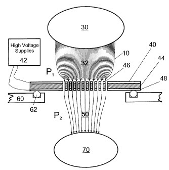
DRAWINGS--REFERENCE NUMBERS
10 ion trajectories
12 equipotential lines
14 ion beams
16 translational stage
equipotential lines
ion source region
32 higher pressure region
first metal laminate
42 voltage supply or supplies
44 first insulator laminate
46 conductance apertures
48 second metal laminate
higher pressure region
52 second insulator laminate
54 third metal laminate
chamber wall
62 0-ring
ion destination region
72 ion collector detector
74 multi-detector array
CA 02527991 2005-12-01
WO 2004/110583 PCT/US2004/018276
11
80 funnel region
82 high transmission element (HTE)
83 HTE apertures
84 funnel lens
85 funnel lens aperture
90 deep well region
DETAILED DESCRIPTION--FIGS 1 AND 2-PREFERRED EMBODIMENT
A preferred embodiment of the ion selective multi-aperture laminate of the
present invention is illustrated in Figs 1 and 2. The multi-aperture laminate
has a
thin first insulated laminate 44 of uniform cross section consisting of an
insulating
material. A layer of metal 40 and 48 is laminated on both sides of the
laminate
44. In the preferred embodiment, 44 is an insulating material, such as glass
or
ceramic. However, it can consist of any other material that can isolate
electrically
the two metal laminates 40 and 48 from each other, such as nylon, polyimide,
Teflon, poly ether ether ketone (PEEK), etc.
The multi-aperture lens is populated with many holes or apertures 46 that
traverse the lens leading from higher pressure ion collection region 32 to
lower
pressure region 50. The inlets of the apertures 46 are downstream of the ion
source region 30 and ion collection region 32. The inlets accept ions from the
region 32. The ions are transfer to the outlet of the apertures 46 and exit
into the
lower pressure region 50 and are collected in destination region 70.
The multi-aperture laminates rest on an 0-ring 62 which isolate the metal
surface 48 from the chamber wall 60. In the preferred embodiment, the wall is
the vacuum chamber of a gas-phase ion detector, such as, but not limited to a
mass spectrometer. The 0-ring also serves as a vacuum seal. The wall is made
of an insulating material, such as, polyimide or glass. However, the wall can
consist of any material that can contain a low pressure, such as, nylon,
polycarbonate, ploy ether ether ketone (PEEK), stainless steel, aluminum, etc.
The metal laminates may be deposited on the base by vapor deposition and
the holes or apertures formed by ablating away the metal and base using a
laser.
CA 02527991 2005-12-01
WO 2004/110583 PCT/US2004/018276
12
Alternatively the multi-aperture lens may be manufactured by using the
techniques of microelectronics fabrication: photolithography for creating
patterns,
etching for removing material, and deposition for coating the surfaces with
specific materials.
The multi-aperture laminate is typically 1 mm to 3 mm in thickness, and has
overall dimensions roughly 30 mm X 30 mm (square shape) to a diameter of
roughly 30 mm (circular shaped). The apertures of the lens are circular in
shape
as shown in Fig 2. In other embodiments, the apertures can be but not limited
to
rectangular or oblong shapes. Figs 7 A through D show a variety or proposed
conductance aperture array patterns that can be oriented to provide high
collection and low relative conductance. The simplest laminate is a single
aperture. We can increase the number of apertures and decrease the diameter
of individual holes in order to reduce overall conductance. The smaller the
aperture size, the higher the demand on and requirement for micro-fabrication
techniques. Precise tolerances on laminate structures and apertures can be
obtained into the sub-micron dimensions. In general, the smaller the apertures
the lower the gas conductance with resulting higher ion flux across the lens.
FIGS 3 - ADDITIONAL EMBODIMENTS
There are various possibilities with regard to the number and type of
laminates
that can make up the laminated multi-aperture lens. Fig 3 shows a cross-
sectional view of multi-aperture lens made up of numerous laminates. Besides
the insulating base 44 and metal laminates 40 and 48, an additional insulating
layer 52 is laminated onto the exposed surface of the metal laminate 48 while
a
third metal layer 54 is laminated onto this second insulating laminate.
Alternatively, the laminated multi-aperture lens can be configured without the
third metal laminate. This increased length of the conductance apertures in
this
embodiment results in different conductance properties (tube vs. pinhole)
which
has advantages for some applications (L is the length of the conductance
tube).
CA 02527991 2005-12-01
WO 2004/110583 PCT/US2004/018276
13
FIGS 4, 5, 6--ADDITIONAL EMBODIMENTS
One additional embodiment seen in Fig 4A introduces an additional high
transmission surface 82 which is a patterned and perforated metal element that
allows the compression of ions to occur remotely from the conductance
apertures
46 (destined by Di, distance between surface 82 and metal laminate 40).
Because the compression of a dispersed ion population from region 30 occurs
some distance away from the conductance apertures, mechanical alignment may
be required to line the beams with the apertures. One method would be electro-
mechanical translational stages 16.
Another additional embodiment seen in Fig 5A introduces an additional high
transmission surface 82 (at a distance of D2) and an additional funnel lens 84
to
allow further compression of the patterned ion beams into a smaller cross
section
bundles of ion beams that are directed at a smaller more condensed patterned
arrays of conductance apertures. The patterned ion beams can be exactly
matched to the patterned arrays of conductance apertures to maximize ion
transmission through a minimum conductance cross-section.
An additional embodiment is shown in Fig 6; a cross sectional view of the ion
selective multi-aperture lens is shown. Fig 6 shows an arrangement as in Fig
1,
however the multi-aperture lens is positioned upstream of a multi-detector
array
74, individual ion streams 56 exiting the apertures 46 can be focused onto
discrete collector electrodes 72, these discrete collectors being electrodes
in a
micro-channel plate or a multi-anode as described in U.S. Patent 5,777,326 to
Rockwood et al. (1998). In other embodiments, the laminated multi-aperture
lens
can serve as a means of introducing ions at or near atmospheric pressure into
a
mass spectrometer equipped with a high pressure interface for the introduction
of
ions into the mass analyzer.
OPERATION--FIGS 1, 2
The manner of using the multi-aperture laminate to introduce ions from
atmospheric pressure ion sources (API), such as but not limited to,
electrospray,
atmospheric pressure chemical ionization, or inductively coupled plasma ion
CA 02527991 2005-12-01
WO 2004/110583 PCT/US2004/018276
14
sources into a vacuum system is as follows. Ions at or near atmospheric
pressure in the ion source region 30 are directed towards the metal surface 40
along the lines of the electrical force fields. Near the metal surface the
ions are
focused into the inlets of the apertures 46 by following the electrical force
fields
emanating outward toward the ion source region 30. At the same time they are
entrained for the most part by the gas also entering the inlets of the
apertures
from region 32 and transferred through the aperture into the low-pressure
region
50 and collected in region 70 (as shown in Fig 1). Through suitable potentials
at
the ion source region 30, metal surfaces 40 and 48, and region 70, the
electrical
force fields are formed. For positive ions, typically the metal laminate 40 is
at
ground potential while the electrical potential of the metal laminate 48 is
selected
to cause the electrical field lines emanating from the apertures to be
converging
into the inlet of the apertures. Region 70 is at a lower potential relative to
metal
laminate 48. The exact potentials will depend on the thickness of the base 44,
the metal laminates 40 and 48; and the diameters of the apertures. The
conditions for ion transmission are that the electric fields inside of the
conductance pathway between the metal laminates must be substantially higher
than the electric field in the collection region 32. Under these conditions,
ions wifl
compress into the cross section of the apertures 46 from the entire incident
surface of ions. Another important condition of operation is that the electric
field
within the conductance pathway (i.e. between the inlet and outlet of 46) must
be
fairly uniform to prevent ions entering the aperture from dispersing to the
walls of
the opening. This will result in charging of surface. Ions are swept through
the
conductance pathway without appreciable radial dispersion by either electric
field
or viscous flow.
It should also be noted that the operation of these ion selective aperture
array
may occur across any number of pressure differentials, including, but not
limited
to atmospheric pressure (AP) to first pumping stage in mass spec; above AP to
AP for high pressure applications; and first pumping stage (-10 Torr) to
second
stage (-0.1 Torr) in a differentially pumped vacuum system. One important
operating boundary will be the discharge limit associated with any given
pressure
CA 02527991 2005-12-01
WO 2004/110583 PCT/US2004/018276
regime. Obviously, we are limited to lower electrostatic field strengths for
compression when operation at the minimum of the Paschen Curve.
It is generally anticipated that the relative pressure between region 32 and
region 50 are at least a factor of two although, factors of 10 or more can be
obtained with increased pumping (with vacuum destinations) or increased
pressure source with above atmospheric pressure sources.
OPERATION OF ADDITIONAL EMBODIMENTS--FIG 3
The aperture length L of the present device may be increased by the addition
of insulated laminate 52 and addition metal laminate 54. The conductance
pathway in this device is operated under the conditions of tube flow which
decreases the conductance for a given cross sectional area of the collective
apertures 46.
In general, the operation of the embodiment illustrated in Fig 3 is the same
as
Fig I with the downhill (in terms of electrostatic field) flow of ions from
source 30
into collection region 32. The electrostatic field penetration from inside the
laminate apertures 46 reaches out and focusses ions from region 32 into the
laminate apertures 46.
It is =anticipated that the electrostatic field down the entire length of L
should be
kept fairly uniform under normal operation. Slightly dispersive fields may be
overcome with the viscous flow within the tube as described in our co-pending
patent (U.S. Patent Application 60/419,699).
OPERATION OF ADDITIONAL EMBODIMENTS--FIGS 4, 5, 6
Figs 4A and 4B are operated in a different mode compared to previous
embodiments in that the ion compression occurs remotely (distance 131) from
the
pressure reduction. The addition of a high transmission element 82 with arrays
of
openings 83 upstream from the conductance laminate openings 46 results in the
compression of the ion population from source 30 into collimated ion beams 14
due to a significant field ratio across element 82. The beams 14 traverse
region
CA 02527991 2008-10-16
16
32 toward the laminated surface in relative straight lines due to the uniform
field in
region 32.
Key to operation of this embodiment is the precise alignment of the ion
beams 14 with the conductance apertures 46 in the laminated surface. We
envision that this alignment requires that the apertures 83 be aligned electro-
optically with aperture 46. This can be accomplished with high precision
assembly
or x-y translational stages 16. These can be controlled and manipulated with
verniers or stepper motors. Detectors (as illustrated in Fig 6) can also be
used to
measure optimal current in the low pressure region and computer data
collection,
feedback, and control can be implemented.
Fig 4B illustrates the potential surface that the ions traverse traveling from
region 30 to region 70. Note that the relative voltages applied to metal
elements
82, 44, and 48, as well as the destination 70 potential are adjusted so that
field is
fairly uniform the entire distance from the high transmission element 82 to
the ion
destination 70. One important operational limitation is the electrostatic
discharge or
breakdown of gases, particularly at lower p'ressures. Also note the
penetration of
the electric field across element 82. Some details of operation of an array of
apertures 82 of this type are described in U.S. Patent 6,744,041.
In some implementations of the present device, some dispersion will be
tolerated at the low pressure side. Such as, when the destination region is
the
entrance of a radio frequency (RF) ion guide. When the ions are introduced
into
the entrance of the RF ion guide they would be refocused on-axis by means of
collisional damping in the pseudo-potential well of the ion guide.
Figs 5A and 5B are operated in a different mode compared to previous
embodiments in that the ion compression occurs remotely (distance D2) from the
pressure reduction. The addition of a high transmission element 82 with arrays
of
openings 83 upstream from the conductance laminate openings 46 results in the
compression of the ion population from source 30 into collimated ion beams 14
due to a significant field ratio across element 82. In this embodiment the ion
CA 02527991 2005-12-01
WO 2004/110583 PCT/US2004/018276
17
beams 14 traverse region 90 through the funnel lens aperture 85 toward the
laminated surface in curved trajectories due to the funnel shaped
electrostatic
fields in funnel region 80 established by funnel lens 84. Resulting in further
focusing the aggregate of ion beams onto a smaller cross-sectional area at the
array of apertures 46 on the laminated surface.
As with Figs 4 the key to operation of this embodiment is the precise
alignment
of the ion beams 14 with the conductance apertures 46 in the laminated
surface.
We envision that this alignment requires that the apertures 83 be lined up
electro-
optically with aperture 46. This can also be accomplished with high precision
assembly or x-y translational stages 16 or feedback control coupled with ion
detectors. Note that alignment with this "double focusing" device will require
more precision both spatially and electro-optically.
Fig 5B illustrates the potential surface that the ions traverse traveling from
region 30 to region 70. Note that the relative voltages applied to metal
elements
82, 84, 44, and 48, as well as the destination 70 potential are adjusted so
that
field is fairly uniform the entire distance from the high transmission element
82 to
the ion destination 70. One important operational caution is the restriction
of the
discharge or breakdown, particularly at lower pressures. Note the focusing
fields
of the funnel region 80 coupled to the deep well region 90.
In some implementations of the present device, some dispersion will be
tolerated at the low pressure side as outline in Fig 4 with RF ion guides.
Alternatively, region 70 may be an intermediate pressure reduction stage
containing a skimmer as part of electrostatic lens elements to focus and
collect
ions exiting the apertures 46 of the multi-aperture lens into region 50.
As shown in Fig 6, when the metal laminated multi-aperture lens is positioned
in front of a multi-detector array 74, individual ion streams 56 exiting the
outlets of
the apertures can be collected at discrete collector electrodes 72, such as
but not
limited to, micro-channel arrays or multi-anodes as described in US Patent
5,77,326 to Rockwood et al. (1998).
CA 02527991 2005-12-01
WO 2004/110583 PCT/US2004/018276
18
CONCLUSION, RAMIFICATIONS, AND SCOPE
Accordingly, the reader will see that the ion enrichment aperture arrays of
this
invention can be used to introduce gas-phase ions and charged particles into
lower pressure regions, such as the vacuum chamber of a mass spectrometer,
without imparting large gas loads on the vacuum system; can be used to accept
and pass into a lower pressure region an incident ion beam with a prescribed
pattern; and can be used to sample an ion beam of whose cross-section is many
times the cross section of the individual openings of the ion enrichment
aperture.
In addition, when an ion enrichment aperture array is used in conjunction with
our
high transmission lens, laminated or uniaminated, dispersive plasma of gas-
phase ions and charged particles can be sampled and introduced into lower
pressure regions without imparting a large gas load on the vacuum system.
Furthermore, the ion enrichment aperture has the additional advantages in
that:
= it permits the production of ion enrichment apertures in a variety of shapes
tailor make for a specific ion source;
= it permits the production of ion enrichment apertures with specific number
and shape of openings tailor made for maximum ion transmission and minimal
gas load on the lower pressure region;
= it allows the sampling of wide incident ion beams, 1-3 mm wide, without
the associated gas load that an aperture 1-3 mm wide would impart on the lower
pressure region.
= it provides an inlet aperture were the electric fields in front of the
aperture
are controllable and can be varied depending on type of ion source, ion
detector
or analyzer in lower pressure region, and pressure across inlet aperture.
Although the description above contain many specifications, these should not
be construed as limiting the scope of the invention but as merely providing
illustrations of some of the presently preferred embodiments of this
invention.
For example, the lens can have other shapes, such as circular, oval,
triangular,
etc.; the openings can have other shapes; insulator and metal laminates can be
CA 02527991 2005-12-01
WO 2004/110583 PCT/US2004/018276
19
manufactured by using the techniques of microelectronics fabrication,
photolithography for creating patterns, etching for removing material, and
deposition for coating the insulating base with specific materials; the number
of
laminates, the relative thickness of adjacent laminates and the size and shape
of
the individual openings can vary depending on the source of ions, the type of
ion
collection region, the pressure drop across the lens or a combination of all
three,
etc.
Thus the scope of the invention should be determined by the appended claims
and their legal equivalents, rather than by the examples given.